EP0728264B1 - Montage und antriebsvorrichtung einer spindel, insbesondere einer textilspindel - Google Patents
Montage und antriebsvorrichtung einer spindel, insbesondere einer textilspindel Download PDFInfo
- Publication number
- EP0728264B1 EP0728264B1 EP95900814A EP95900814A EP0728264B1 EP 0728264 B1 EP0728264 B1 EP 0728264B1 EP 95900814 A EP95900814 A EP 95900814A EP 95900814 A EP95900814 A EP 95900814A EP 0728264 B1 EP0728264 B1 EP 0728264B1
- Authority
- EP
- European Patent Office
- Prior art keywords
- radial
- tube
- magnetic bearings
- spindle
- electric motor
- Prior art date
- Legal status (The legal status is an assumption and is not a legal conclusion. Google has not performed a legal analysis and makes no representation as to the accuracy of the status listed.)
- Expired - Lifetime
Links
Images

Classifications
-
- F—MECHANICAL ENGINEERING; LIGHTING; HEATING; WEAPONS; BLASTING
- F16—ENGINEERING ELEMENTS AND UNITS; GENERAL MEASURES FOR PRODUCING AND MAINTAINING EFFECTIVE FUNCTIONING OF MACHINES OR INSTALLATIONS; THERMAL INSULATION IN GENERAL
- F16C—SHAFTS; FLEXIBLE SHAFTS; ELEMENTS OR CRANKSHAFT MECHANISMS; ROTARY BODIES OTHER THAN GEARING ELEMENTS; BEARINGS
- F16C39/00—Relieving load on bearings
- F16C39/02—Relieving load on bearings using mechanical means
-
- B—PERFORMING OPERATIONS; TRANSPORTING
- B23—MACHINE TOOLS; METAL-WORKING NOT OTHERWISE PROVIDED FOR
- B23Q—DETAILS, COMPONENTS, OR ACCESSORIES FOR MACHINE TOOLS, e.g. ARRANGEMENTS FOR COPYING OR CONTROLLING; MACHINE TOOLS IN GENERAL CHARACTERISED BY THE CONSTRUCTION OF PARTICULAR DETAILS OR COMPONENTS; COMBINATIONS OR ASSOCIATIONS OF METAL-WORKING MACHINES, NOT DIRECTED TO A PARTICULAR RESULT
- B23Q1/00—Members which are comprised in the general build-up of a form of machine, particularly relatively large fixed members
- B23Q1/70—Stationary or movable members for carrying working-spindles for attachment of tools or work
-
- D—TEXTILES; PAPER
- D01—NATURAL OR MAN-MADE THREADS OR FIBRES; SPINNING
- D01H—SPINNING OR TWISTING
- D01H7/00—Spinning or twisting arrangements
- D01H7/02—Spinning or twisting arrangements for imparting permanent twist
- D01H7/04—Spindles
- D01H7/08—Mounting arrangements
- D01H7/12—Bolsters; Bearings
-
- F—MECHANICAL ENGINEERING; LIGHTING; HEATING; WEAPONS; BLASTING
- F16—ENGINEERING ELEMENTS AND UNITS; GENERAL MEASURES FOR PRODUCING AND MAINTAINING EFFECTIVE FUNCTIONING OF MACHINES OR INSTALLATIONS; THERMAL INSULATION IN GENERAL
- F16C—SHAFTS; FLEXIBLE SHAFTS; ELEMENTS OR CRANKSHAFT MECHANISMS; ROTARY BODIES OTHER THAN GEARING ELEMENTS; BEARINGS
- F16C32/00—Bearings not otherwise provided for
- F16C32/04—Bearings not otherwise provided for using magnetic or electric supporting means
- F16C32/0406—Magnetic bearings
- F16C32/044—Active magnetic bearings
- F16C32/0459—Details of the magnetic circuit
- F16C32/0461—Details of the magnetic circuit of stationary parts of the magnetic circuit
-
- F—MECHANICAL ENGINEERING; LIGHTING; HEATING; WEAPONS; BLASTING
- F16—ENGINEERING ELEMENTS AND UNITS; GENERAL MEASURES FOR PRODUCING AND MAINTAINING EFFECTIVE FUNCTIONING OF MACHINES OR INSTALLATIONS; THERMAL INSULATION IN GENERAL
- F16C—SHAFTS; FLEXIBLE SHAFTS; ELEMENTS OR CRANKSHAFT MECHANISMS; ROTARY BODIES OTHER THAN GEARING ELEMENTS; BEARINGS
- F16C32/00—Bearings not otherwise provided for
- F16C32/04—Bearings not otherwise provided for using magnetic or electric supporting means
- F16C32/0406—Magnetic bearings
- F16C32/044—Active magnetic bearings
- F16C32/047—Details of housings; Mounting of active magnetic bearings
-
- F—MECHANICAL ENGINEERING; LIGHTING; HEATING; WEAPONS; BLASTING
- F16—ENGINEERING ELEMENTS AND UNITS; GENERAL MEASURES FOR PRODUCING AND MAINTAINING EFFECTIVE FUNCTIONING OF MACHINES OR INSTALLATIONS; THERMAL INSULATION IN GENERAL
- F16C—SHAFTS; FLEXIBLE SHAFTS; ELEMENTS OR CRANKSHAFT MECHANISMS; ROTARY BODIES OTHER THAN GEARING ELEMENTS; BEARINGS
- F16C33/00—Parts of bearings; Special methods for making bearings or parts thereof
- F16C33/72—Sealings
-
- H—ELECTRICITY
- H02—GENERATION; CONVERSION OR DISTRIBUTION OF ELECTRIC POWER
- H02K—DYNAMO-ELECTRIC MACHINES
- H02K11/00—Structural association of dynamo-electric machines with electric components or with devices for shielding, monitoring or protection
- H02K11/30—Structural association with control circuits or drive circuits
- H02K11/33—Drive circuits, e.g. power electronics
-
- H—ELECTRICITY
- H02—GENERATION; CONVERSION OR DISTRIBUTION OF ELECTRIC POWER
- H02K—DYNAMO-ELECTRIC MACHINES
- H02K5/00—Casings; Enclosures; Supports
- H02K5/04—Casings or enclosures characterised by the shape, form or construction thereof
- H02K5/12—Casings or enclosures characterised by the shape, form or construction thereof specially adapted for operating in liquid or gas
- H02K5/124—Sealing of shafts
-
- H—ELECTRICITY
- H02—GENERATION; CONVERSION OR DISTRIBUTION OF ELECTRIC POWER
- H02K—DYNAMO-ELECTRIC MACHINES
- H02K7/00—Arrangements for handling mechanical energy structurally associated with dynamo-electric machines, e.g. structural association with mechanical driving motors or auxiliary dynamo-electric machines
- H02K7/08—Structural association with bearings
- H02K7/09—Structural association with bearings with magnetic bearings
-
- H—ELECTRICITY
- H02—GENERATION; CONVERSION OR DISTRIBUTION OF ELECTRIC POWER
- H02K—DYNAMO-ELECTRIC MACHINES
- H02K7/00—Arrangements for handling mechanical energy structurally associated with dynamo-electric machines, e.g. structural association with mechanical driving motors or auxiliary dynamo-electric machines
- H02K7/14—Structural association with mechanical loads, e.g. with hand-held machine tools or fans
-
- F—MECHANICAL ENGINEERING; LIGHTING; HEATING; WEAPONS; BLASTING
- F16—ENGINEERING ELEMENTS AND UNITS; GENERAL MEASURES FOR PRODUCING AND MAINTAINING EFFECTIVE FUNCTIONING OF MACHINES OR INSTALLATIONS; THERMAL INSULATION IN GENERAL
- F16C—SHAFTS; FLEXIBLE SHAFTS; ELEMENTS OR CRANKSHAFT MECHANISMS; ROTARY BODIES OTHER THAN GEARING ELEMENTS; BEARINGS
- F16C2322/00—Apparatus used in shaping articles
- F16C2322/39—General buildup of machine tools, e.g. spindles, slides, actuators
-
- F—MECHANICAL ENGINEERING; LIGHTING; HEATING; WEAPONS; BLASTING
- F16—ENGINEERING ELEMENTS AND UNITS; GENERAL MEASURES FOR PRODUCING AND MAINTAINING EFFECTIVE FUNCTIONING OF MACHINES OR INSTALLATIONS; THERMAL INSULATION IN GENERAL
- F16C—SHAFTS; FLEXIBLE SHAFTS; ELEMENTS OR CRANKSHAFT MECHANISMS; ROTARY BODIES OTHER THAN GEARING ELEMENTS; BEARINGS
- F16C2340/00—Apparatus for treating textiles
- F16C2340/18—Apparatus for spinning or twisting
-
- F—MECHANICAL ENGINEERING; LIGHTING; HEATING; WEAPONS; BLASTING
- F16—ENGINEERING ELEMENTS AND UNITS; GENERAL MEASURES FOR PRODUCING AND MAINTAINING EFFECTIVE FUNCTIONING OF MACHINES OR INSTALLATIONS; THERMAL INSULATION IN GENERAL
- F16C—SHAFTS; FLEXIBLE SHAFTS; ELEMENTS OR CRANKSHAFT MECHANISMS; ROTARY BODIES OTHER THAN GEARING ELEMENTS; BEARINGS
- F16C2380/00—Electrical apparatus
- F16C2380/26—Dynamo-electric machines or combinations therewith, e.g. electro-motors and generators
Definitions
- the present invention relates to a mounting device and for driving a textile spindle comprising a tube which is mounted relative to to a frame using first and second radial bearings and is rotated using an electric motor.
- a textile spindle comprising a tube which is mounted relative to to a frame using first and second radial bearings and is rotated using an electric motor.
- An example such a spindle comprises a vertical tube which may have an internal diameter of the order of 30 to 40 mm, which is mounted inside a frame in a housing with a predetermined clearance so that this tube can rotate without contact with the housing wall.
- the tube is extended at its upper part by a part of reduced diameter which is mounted on conventional bearings such as bearings with balls, and is rotated by an electric motor.
- a thread to put under coil form is introduced inside the tube in which it can be entrained by centrifugal force against the internal wall of the tube so as to constitute inside this tube a coil of wire which will then be extracted from this tube by the opening at the bottom.
- the tube is driven by the engine at rotational speeds of the order of, for example, 300 rpm.
- the present invention aims to remedy the aforementioned drawbacks and to allow the mounting of rotating tubular members, such as pins, the reliability, service life and production capacity are increased.
- Another object of the invention is to produce a spindle assembly having a minimum of disturbances in the centrifugal effect and whose losses by aerodynamic friction is also very greatly reduced.
- a spindle including a textile spindle comprising a tube which is mounted relative to a frame using first and second radial magnetic bearings at axial flow and is driven in rotation using a motor characterized in that the tube is mounted without contact with respect to the casing-shaped frame, using said tube first and second axial magnetic bearings with axial flux of the active type, and arranged respectively at a first end of the tube and at a second end of it and between which is interposed said motor of the motor type electric, in that each of the radial active magnetic bearings comprises a stator magnetic circuit composed of four axial flow elements joined according to axial planes distributed around the tube, and in that means are provided to create magnetic bearings inside the spindle at the air gap radial and electric motor reduced pressure on the order of a few hundreds of pascals to a few thousand pascals.
- the spindle according to the invention has increased reliability and longer service life.
- the depression created in air gap level of radial magnetic bearings and electric motor contributes to a significant reduction in friction losses aerodynamics, even with a high rotation speed for example of the order from 800 to 1000 revolutions per second.
- the magnetic stator circuits with four contiguous elements of the bearings magnetic active radials are each composed of two subsets of four contiguous elements joined according to a radial joint plane and held together by pliers or circlips.
- This type of assembly contributes to simplify and reduce the manufacturing cost of the entire system.
- the magnetic stator circuits of the magnetic bearings Radial assets are made of isolated grain iron powder agglomerated by isostatic hot pressing.
- At least one of the first and second active radial magnetic bearings includes a magnetic circuit stator with a second subset of four contiguous elements, to also play the role of an axial bearing with respect to a horizontal flange of the tube.
- the low pressure prevailing at the air gap of the magnetic bearings radials and the electric motor which can be for example of the order of 1300 pascals, can be carried out during the initial assembly or be maintained permanently in operation using a low flow vacuum pump.
- the spindle according to the invention can comprise at least one of its ends a floating sealing ring fixed by a flexible membrane on the spindle housing.
- the floating ring can be made of graphite, ceramic or carbon, such as the diamond ADLC carbon material, and may have a stroke flexible in the radial direction limited to a few hundredths of a millimeter so as to also constitute an emergency landing.
- FIG. 1 shows an example of a device according to the invention, of assembly and training of a spindle such as a textile spinning spindle which is advantageously positioned vertically.
- An outer casing 50 is composed of several cylindrical elements 52, 54, 55 juxtaposed and front walls 51, 53 separated to facilitate mounting elements incorporated in the casing 50.
- a metal tube 10 which may have for example a length of on the order of 200 mm and an internal diameter on the order of 30 to 50 mm is mounted without contact. inside the casing 50 using an active radial magnetic bearing upper 60 and a lower radial active magnetic bearing 70 whose structure will be described later in detail.
- An electric motor 80 which can be of the asynchronous type with a solid rotor and comprises a stator inductor 81 provided with windings 82 is disposed between the radial magnetic bearings 60 and 70.
- the outer surface of the tube 10 is preferably covered with a weak deposit of copper 84 or provided with grooves 83 in its part located opposite the electric motor 80 provided for training in rotation of the tube 10 in order to reduce the sliding losses.
- the tube 10 remains massive without particular lamination in its upper and lower parts located opposite the radial magnetic bearings 60, 70.
- a flexible printed circuit 30 is disposed on the casing 50 in the vicinity of its central part 55. Connections with wires (not shown in the drawing) supplying the windings 82 of the motor 80, the coils 64, 74 of the bearings radials 60, 70 and detectors 66, 76 of the position of the rotor 10, are produced at level of the flexible printed circuit 30 which also includes connectors connection with external motor 80 and bearing control circuits magnetic 60, 70.
- the various elements for rotating the tube 10 and suspension thereof are integrated by overmolding inside the housing 50 and have precisely defined positions relative to the tube 10.
- the tube 10 constituting the rotating spindle can be rotated at speeds of the order of 800 to 1000 revolutions per second.
- the active magnetic bearings 60, 70 and the electric motor 80 are entirely adapted to allow such speeds of rotation of the tube 10.
- aerodynamic losses in the air gap magnetic bearings 60, 70 and the motor 80 are of the order of 200 to 400 watts, which can be a hindrance to the proper functioning of the system.
- the pressure ambient inside the rotating machine is reduced to a value between a few hundred pascals and a few thousand pascals, for example at around 1300 pascals.
- the aerodynamic friction losses in the air gap of the magnetic and motor bearings are significantly decreased and the system can work very well with a high rotation speed which leads to excellent performance.
- the vacuum in the air gap between the tube 10 and the static elements immobilized by overmolding can be created during an initial setting operation work of the spindle or be kept permanently in operation by a very low flow vacuum pump associated with the spindle.
- the good sealing of the outlet of the rotor 10 is ensured by a ring floating 21 or 22, centered by an air bearing effect around the rotor 10 and fixed by a flexible membrane on the part 51 constituting a front end of the casing 50.
- a floating ring similar to one of the rings 21 or 22 can also be attached via a flexible membrane on the lower front piece 53 of housing 50.
- the floating sealing ring intended to limit the air pressure in the air gap of the spindle can be mounted flexible in the direction axial (ring 22) or radially (ring 21) depending on the type of seal wanted.
- a radially flexible floating ring, like ring 21, is generally more favorable to avoid the charge due to atmospheric pressure.
- a floating sealing ring such as the ring 21 can also serve as a smooth auxiliary bearing if carried out, at least partially, in a material of the family of carbons or graphites.
- a floating ring serving as a smooth auxiliary bearing can have a contact surface made of ceramic or diamond carbon ADLC (Amorphous Diamond Like Carbon).
- ADLC Amorphous Diamond Like Carbon
- a floating ring may have a flexible stroke limited to a few hundredths of a millimeter and be made of so as to find positive support at a distance of about 0.10 to 0.15 mm, so as to play the emergency stop function in the event of a failure or stop of the active magnetic suspension. Note that the flexible fixing of the ring also serves as an emergency stop helps to dampen vibrations by landing case.
- the radial magnetic bearings 60, 70 cooperate directly with the massive wall of tube 10 made of ferromagnetic material and have stators whose shape is such that it minimizes variations in the magnetic field.
- the stator electromagnets of the radial bearings 60, 70 have a shape zero sequence, that is to say with axial flow. They advantageously have a electromagnet yoke made up of two parts 61, 62 respectively 71, 72 pressed against each other with a joint plane 63 respectively 73 located in a radial plane.
- Pliers or circlips 65 respectively 75 make it possible to keep the two cylinder head halves 61, 62 pressed together 71, 72 respectively.
- the coils 64 respectively 74 can easily be prefabricated and introduced around a first part of cylinder head 61 respectively 71 before assembly of the two parts 61, 62 respectively 71, 72.
- the electromagnets 61, 62 and 71, 72 can be made of iron powder with agglomerated isolated grains, therefore directly to dimension, by isostatic pressing without any resumption of machining.
- the stator of each radial magnetic bearing 60, 70 is made of four elements 101 to 104 axial flow joints without notch between these four elements. This contributes to avoid magnetic losses in the rotor in the vertical position of the spindle, or considerably reduced in horizontal position.
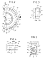
- FIG. 2 the four contiguous elements 101 to 104 of an electromagnet radial bearings distributed in a ring around a central passage in which is engaged the tube 10 which constitutes the rotor of the magnetic bearing by which close the magnetic field lines.
- Figures 3 and 4 show more particularly the elements 101 and 102 represented on the right of FIG. 2.
- the four elements 101 to 104 which each include a coil 114, 124, 134, 144 are identical.
- Element 101 includes a U-shaped structure with two lateral branches parallel 111, 112 in the form of quarter crowns arranged in planes radial and an arcuate branch 113 joining the lateral branches 111, 112 and around which is placed a coil 114.
- assembly is facilitated if each element such as element 101 is made in two parts separated by a joint plane 115 located in a radial plane.
- the division of the arched branch 113 into two integral halves 113a, 113b planar parallel branches 111, 112 respectively makes it possible easy introduction of a prefabricated coil 114 before clipping the two halves magnetic circuit 111, 113a and 112, 113b.
- the element 102 comprises constituent parts 121, 122, 123a, 123b, 124, 125 which are strictly identical to the constituent parts 111, 112, 113a, 113c, 114, 115 of element 101 and elements 103 and 104 have also the same structure.
- the elements 101, 102, 103, 104 are in contact the with each other along axial planes 110, 120, 130 distributed in a cross.
- the different stator coils 114, 124, 134, 144 in the shape of a bean distributed around the tube 10 have a shape which reduces the variation of the field magnetic radial on a lathe and create between them small free spaces for allow the two halves of the electromagnet to be clipped using the circlips 65, 75 (fig 1).
- FIG. 1 shows by way of example radial detectors 66, 76 arranged near the radial bearings 60, 70.
- the detectors 66, 76 can be produced in a variety of ways and can be conical type with successive poles on a lathe or type homopolar (axial flow) like the bearing electromagnets to be less sensitive to pollution from the neighboring electric motor 80.
- the detectors 66, 76 work directly in repulsion on the solid rotor 10, without it being attached sheet bundle on the rotor, with a carrier frequency which can be reduced less than 5 kHz. More particularly, the detectors 66, 76 are advantageously also made of iron powder with isolated agglomerated grains by isostatic pressure.
- One or more active axial magnetic bearings can also be used to axially hold the rotor 10 relative to the frame.
- FIG. 1 there is shown a tube 10 having at its lower part a flange 17 on which comes the free end 77 of the lower part 72 of the radial bearing electromagnet 70.
- the magnetic bearing 70 serves also of axial bearing with respect to the tube 10.
- An axial detector 90 is arranged opposite the tube 10 concentrically with the coil 74 of the magnetic bearing 70.
- the axial detector 90 can comprise stator elements 94, 95 cooperating with an insert 96 placed in the wall of the tube 10 opposite the elements 94, 95.
- FIG. 5 shows an alternative embodiment in which the part lower 72 of the magnetic bearing electromagnet 70 constitutes a part conical polar 78 cooperating with a free end 18 of the tube 10 which is also tapered so as to create a bearing with radial and axial action.
- a floating sealing ring 23 which can be similar to upper ring 22.
Landscapes
- Engineering & Computer Science (AREA)
- General Engineering & Computer Science (AREA)
- Mechanical Engineering (AREA)
- Power Engineering (AREA)
- Textile Engineering (AREA)
- Microelectronics & Electronic Packaging (AREA)
- Magnetic Bearings And Hydrostatic Bearings (AREA)
- Connection Of Motors, Electrical Generators, Mechanical Devices, And The Like (AREA)
- Spinning Or Twisting Of Yarns (AREA)
- Turning (AREA)
Claims (12)
- Vorrichtung zu Montage und zum Antrieb einer Spindel, insbesondere einer Textilspindel, mit einem Rohr (10), das in Bezug auf ein Maschinengestell (50) mit Hilfe eines ersten und zweiten magnetischen Radiallagers (60, 70) mit axialem Magnetfluß angebracht ist und zu Drehung mit Hilfe eines Motors (80) angetrieben ist,
dadurch gekennzeichnet, daß das Rohr (10) in Bezug auf das Maschinengestell (50) in Form eines Gehäuses ohne Berührung mit Hilfe des genannten ersten und zweiten magnetischen Radiallagers (60, 70) mit axialem Magnetfluß angebracht ist, die der Art nach aktive Magnetlager sind und jeweils an einem ersten bzw. zweiten Ende des Rohres (10) angeordnet sind, und zwischen denen der genannte Motor (80) angeordnet ist, der der Art nach ein Elektromotor ist, daß jedes der aktiven magnetischen Radiallager (60, 70) eine magnetische Statorschaltung aufweist, die aus vier Elementen (101 bis 104) mit axialem Magnetfluß zusammengesetzt ist, die längs axialer Ebenen (110, 120, 130, 140) zusammengefügt sind und rund um das Rohr (10) verteilt sind, und daß Mittel vorgesehen sind, um im Inneren der Spindel auf Höhe des Luftspalts dei magnetischen Radiallager (60, 70) und des Elektromotors (80) einen verringerten Druck in der Größenordnung von einigen hundert Pascal bis zu einigen tausend Pascal zu erzeugen. - Vorrichtung nach Anspruch 1, dadurch gekennzeichnet, daß die magnetischen Statorschaltungen mit vier aneinander angrenzenden Elementen (101 bis 104) der aktiven magnetischen Radiallager (60, 70) jeweils aus zwei Untergruppen (61, 62; 71, 72) aus vier aneinander angrenzenden Elementen zusammengesetzt sind, die längs einer radialen Verbindungsebene (63; 73) vereint sind und durch Klemmen oder Federbügel (65; 75) zusammenmontiert sind.
- Vorrichtung nach Anspruch 1 oder Anspruch 2, dadurch gekennzeichnet, daß die magnetischen Statorschaltungen der aktiven magnetischen Radiallager (60; 70) aus Eisenpulver mit isolierten Körnern gebildet sind, die durch isostatisches Warmverpressen zusammengebacken sind.
- Vorrichtung nach Anspruch 2, dadurch gekennzeichnet, daß mindestens das eine (70) des ersten und zweiten aktiven, magnetischen Radiallagers (70) eine magnetische Statorschaltung mit einer zweiten Untergruppe (72) aus vier aneinander angrenzenden Elementen aufeist, die in Bezug auf die erste Untergruppe (71) aus vier aneinander angrenzenden Elementen asymmetrisch ist, um auch die Rolle eines Axiallagers gegenüber einem horizontalen Flansch (17) des Rohres (10) zu spielen.
- Vorrichtung nach irgendeinem der Ansprüche 1 bis 4, dadurch gekennzeichnet, daß der niedrige Druck, der auf Höhe des Luftspalts der magnetischen Radiallager (60; 70) und des Elektromotors (80) vorliegt, in der Größenordnung von 1300 Pascal liegt.
- Vorrichtung nach irgendeinem der Ansprüche 1 bis 5, dadurch gekennzeichnet, daß der niedrige Druck, der auf Höhe des Luftspalts der magnetischer Radiallager (60; 70) und des Elektromotors (80) vorliegt, während der Montage hergestellt ist.
- Vorrichtung nach irgendeinem der Ansprüche 1 bis 5, dadurch gekennzeichnet, daß der niedrige Druck, der auf Höhe des Luftspalts der magnetischen Radiallager (60, 70) und des Elektromotors (80) vorliegt, ständig mit Hilfe einer Vakuumpumpe mit geringem Durchsatz aufrechterhalten wird.
- Vorrichtung nach irgendeinem der Ansprüche 1 bis 7, dadurch gekennzeichnet, daß sie mindestens an einem ihrer Enden einen schwimmenden Dichtungsring (22) aufweist, der durch eine weiche Membran auf dem Gehäuse (51) der Spindel befestigt ist.
- Vorrichtung nach irgendeinem der Ansprüche 1 bis 7, dadurch gekennzeichnet, daß sie mindestens an einem ihrer Enden einen schwimmenden Dichtungsring (21) aufweist, der durch eine weiche Membran auf dem Gehäuse (51) der Spindel befestigt ist und aus Graphit, Keramik oder Carbon bzw. Kohlenstoff, wie etwa einem Diamant-Carbonmaterial ADLC, hergestellt ist und einen in radialer Richtung auf einige Hundertstel Millimeter begrenzten Bewegungsweg aufweist, um auf diese Weise auch ein Sicherheitslager zu bilden.
- Vorrichtung nach irgendeinem der Ansprüche 1 bis 9, dadurch gekennzeichnet, daß sie Steuerschaltungen für die aktiven magnetischen Lager (60, 70) und den Elektromotor (80) aufweist, die mindestens teilweise auf einer flexiblen, gedruckten Schaltung (30) angeordnet sind, die auf dem Maschinengestell (50) in Form einer äußeren Kappe an dem Elektromotor (80) befestigt ist.
- Vorrichtung nach irgendeinem der Ansprüche 1 bis 10, dadurch gekennzeichnet, daß sie radiale Fühler (66, 76) und axiale Fühler (90) aus Eisenpulver aus isolierten Körnern aufweist, die durch isostatisches Warmverpressen zusammengebacken sind und unmittelbar durch Abstoßung mit der massiven Wand des Rohres (10) zusammenwirken.
- Vorrichtung nach irgendeinem der Ansprüche 1 bis 11, dadurch gekennzeichnet, daß sie einen Formmantel für die Anordnung von Elementen aufweist, die zwischen dem Rohr (10) und dem äußeren Maschinengestell (50) angeordnet sind.
Applications Claiming Priority (3)
| Application Number | Priority Date | Filing Date | Title |
|---|---|---|---|
| FR9313332 | 1993-11-09 | ||
| FR9313332A FR2712358B1 (fr) | 1993-11-09 | 1993-11-09 | Dispositif de montage et d'entraînement d'une broche, notamment d'une broche textile. |
| PCT/FR1994/001303 WO1995013480A1 (fr) | 1993-11-09 | 1994-11-08 | Dispositif de montage et d'entrainement d'une broche, notamment d'une broche textile |
Publications (2)
| Publication Number | Publication Date |
|---|---|
| EP0728264A1 EP0728264A1 (de) | 1996-08-28 |
| EP0728264B1 true EP0728264B1 (de) | 1999-03-17 |
Family
ID=9452663
Family Applications (1)
| Application Number | Title | Priority Date | Filing Date |
|---|---|---|---|
| EP95900814A Expired - Lifetime EP0728264B1 (de) | 1993-11-09 | 1994-11-08 | Montage und antriebsvorrichtung einer spindel, insbesondere einer textilspindel |
Country Status (6)
| Country | Link |
|---|---|
| US (1) | US5973430A (de) |
| EP (1) | EP0728264B1 (de) |
| JP (1) | JP3258021B2 (de) |
| DE (1) | DE69417253T2 (de) |
| FR (1) | FR2712358B1 (de) |
| WO (1) | WO1995013480A1 (de) |
Families Citing this family (13)
| Publication number | Priority date | Publication date | Assignee | Title |
|---|---|---|---|---|
| DE19823630C2 (de) * | 1998-05-27 | 2003-08-21 | Pmdm Prec Motors Deutsche Mine | Motorlager für schnelldrehende Kleinmotoren |
| JP2002317340A (ja) * | 2001-02-01 | 2002-10-31 | Neumag Gmbh & Co Kg | 糸を案内し、加熱しかつ搬送するためのゴデット |
| JP4106218B2 (ja) * | 2001-02-01 | 2008-06-25 | ノイマーク ゲゼルシャフト ミット ベシュレンクテル ハフツング ウント コンパニー コマンディートゲゼルシャフト | 少なくとも1つの糸を案内するためのゴデット |
| DE10130950A1 (de) * | 2001-06-27 | 2003-01-23 | Behr Gmbh & Co | Elektromotor |
| DE102005030724A1 (de) * | 2005-07-01 | 2007-01-04 | Levitec Gbmh | Elektrisches Magnetlagersystem |
| FR2893684B1 (fr) * | 2005-11-24 | 2009-07-03 | Mecanique Magnetique Sa Soc D | Agencement de paliers de secours pour machine tournante a paliers magnetiques actifs |
| FR2897911B1 (fr) * | 2006-02-27 | 2009-03-27 | Mecanique Magnetique Sa Soc D | Palier magnetique actif chemise |
| FR2947678A1 (fr) * | 2009-07-03 | 2011-01-07 | Mecanique Magnetique Sa | Machine tournante chemisee et son procede de fabrication |
| RU2479095C2 (ru) * | 2011-05-20 | 2013-04-10 | Федеральное Государственное Автономное Образовательное Учреждение Высшего Профессионального Образования "Дальневосточный Федеральный Университет" (Двфу) | Электрошпиндель |
| CN102537048A (zh) * | 2012-02-08 | 2012-07-04 | 南京信息工程大学 | 一种可控制径向扭转的轴向磁轴承 |
| WO2014182646A1 (en) * | 2013-05-09 | 2014-11-13 | Dresser-Rand Company | Magnetic bearing protection device |
| CH711652A1 (de) * | 2015-10-16 | 2017-04-28 | Rieter Ag Maschf | Spindelunterteil für Spindeln einer Ringspinnmaschine. |
| EP3197029B1 (de) * | 2016-01-19 | 2019-05-29 | Gebrüder Klöcker GmbH | Elektromotorisch arbeitende vorrichtung zum bilden einer dreherkante, insbesondere für eine webmaschine, sowie projektilwebmaschine mit einer solchen vorrichtung |
Family Cites Families (18)
| Publication number | Priority date | Publication date | Assignee | Title |
|---|---|---|---|---|
| US3888553A (en) * | 1973-02-27 | 1975-06-10 | Teldix Gmbh | Levitated rotary magnetic device |
| DE2349033C3 (de) * | 1973-09-29 | 1984-08-30 | Leybold-Heraeus Gmbh, 5000 Koeln | Turbomolekularpumpe |
| US4180946A (en) * | 1975-10-02 | 1980-01-01 | Maurice Brunet | Tool holding spindle assembly particularly for a grinding machine |
| DE3029523C2 (de) * | 1980-08-04 | 1984-11-22 | Christensen, Inc., Salt Lake City, Utah | Generator zur Energieversorgung von innerhalb eines Bohrloches angeordneten Verbrauchern |
| US4473259A (en) * | 1980-12-24 | 1984-09-25 | The United States Of America As Represented By The Administrator Of The National Aeronautics And Space Administration | Linear magnetic bearings |
| US4389849A (en) * | 1981-10-02 | 1983-06-28 | Beggs James M Administrator Of | Stirling cycle cryogenic cooler |
| DE3343186A1 (de) * | 1983-11-29 | 1985-06-05 | Fraunhofer-Gesellschaft zur Förderung der angewandten Forschung e.V., 8000 München | Magnetische rotorlagerung |
| FR2570488B1 (fr) * | 1984-09-19 | 1987-01-09 | Europ Propulsion | Dispositif de detection magnetique des deplacements radiaux d'un rotor |
| US4810917A (en) * | 1985-05-28 | 1989-03-07 | Autotech Corporation | Digital resolver/encoder assembly |
| NL8502058A (nl) * | 1985-07-17 | 1987-02-16 | Philips Nv | Electrische machine met magnetische lagervoorzieningen. |
| FR2612266B1 (fr) * | 1987-03-13 | 1989-07-13 | Aerospatiale | Palier magnetique pour le centrage actif, selon au moins un axe, d'un corps mobile selon un autre corps |
| JP2852747B2 (ja) * | 1988-03-18 | 1999-02-03 | セイコー精機株式会社 | 内面研削盤 |
| FR2630792B1 (fr) * | 1988-04-29 | 1992-03-06 | Mecanique Magnetique Sa | Palier auxiliaire a stator en graphite pour arbre tournant monte sur paliers magnetiques |
| US5007972A (en) * | 1988-06-09 | 1991-04-16 | The Charles Stark Draper Laboratory, Inc. | Samarium-transition metal magnet formation |
| JPH0235217A (ja) * | 1988-07-21 | 1990-02-05 | Koyo Seiko Co Ltd | 磁気軸受スピンドル装置 |
| JPH0389020A (ja) * | 1989-06-23 | 1991-04-15 | Nippon Thompson Co Ltd | 磁性流体軸受 |
| DE3931661A1 (de) * | 1989-08-25 | 1991-04-04 | Leybold Ag | Magnetgelagerte vakuumpumpe |
| EP0512516B1 (de) * | 1991-05-08 | 1995-12-20 | Koyo Seiko Co., Ltd. | Magnetische Antriebsvorrichtung |
-
1993
- 1993-11-09 FR FR9313332A patent/FR2712358B1/fr not_active Expired - Fee Related
-
1994
- 1994-11-08 EP EP95900814A patent/EP0728264B1/de not_active Expired - Lifetime
- 1994-11-08 US US08/640,887 patent/US5973430A/en not_active Expired - Lifetime
- 1994-11-08 JP JP51363995A patent/JP3258021B2/ja not_active Expired - Lifetime
- 1994-11-08 WO PCT/FR1994/001303 patent/WO1995013480A1/fr not_active Ceased
- 1994-11-08 DE DE69417253T patent/DE69417253T2/de not_active Expired - Fee Related
Also Published As
| Publication number | Publication date |
|---|---|
| JPH09504856A (ja) | 1997-05-13 |
| EP0728264A1 (de) | 1996-08-28 |
| JP3258021B2 (ja) | 2002-02-18 |
| WO1995013480A1 (fr) | 1995-05-18 |
| DE69417253T2 (de) | 1999-07-08 |
| DE69417253D1 (de) | 1999-04-22 |
| FR2712358B1 (fr) | 1996-02-09 |
| US5973430A (en) | 1999-10-26 |
| FR2712358A1 (fr) | 1995-05-19 |
Similar Documents
| Publication | Publication Date | Title |
|---|---|---|
| EP0728264B1 (de) | Montage und antriebsvorrichtung einer spindel, insbesondere einer textilspindel | |
| FR2499647A1 (fr) | Perfectionnements aux accouplements magnetiques hermetiques | |
| FR2516995A1 (fr) | Palier hydrodynamique a film de fluide | |
| FR2462615A1 (fr) | Dispositif d'accouplement electromagnetique | |
| WO2001018401A1 (fr) | Pompe a entrainement magnetique | |
| EP0248798B1 (de) | Elektrischer synchronmotor mit dauermagnetischem läufer und herstellungsverfahren dieses motors | |
| EP3895294B1 (de) | Rotor mit einer nicht durchgehenden welle und zugehörige rotierende elektrische maschine | |
| WO1992011686A1 (fr) | Actionneur electromagnetique monophase rotatif | |
| FR2796679A1 (fr) | Palier a roulement instrumente | |
| EP0697524B1 (de) | Turbomolekular-Vakuumpumpe | |
| EP3121942B1 (de) | Brems- und sperrvorrichtung für den läufer einer synchronmaschine | |
| FR2501933A1 (fr) | Unite de ventilation, notamment pour un moteur a combustion interne | |
| EP3878081A1 (de) | Käfigläufer und asynchrone elektrische maschine mit einem solchen läufer | |
| FR2957729A1 (fr) | Moteur electrique a aimants permanents comportant un stator fractionne | |
| EP0706255A1 (de) | Kommutatorelektrische Maschine, insbesondere Gleichstromelektromotor | |
| FR2785734A1 (fr) | Dispositif magnetique pour corps tournant et ensemble mecanique le comportant | |
| EP0173618A1 (de) | Induktor mit magnetischem Joch für eine Anlage zur Herstellung von Glasfasern | |
| FR2723490A1 (fr) | Machine electrique tournante comme un moteur electrique a inducteur constitue par des aimants permanents. | |
| FR2717947A1 (fr) | Actionneur électromagnétique rotatif à débattement angulaire limité. | |
| FR2922060A1 (fr) | Machine electrique tournante comportant deux stators | |
| FR2745664A1 (fr) | Moteur piezoelectrique a onde progressive | |
| FR2513710A1 (fr) | Ensemble d'entrainement synchrone par voie magnetique avec cloison separatrice feuilletee | |
| FR2570229A1 (fr) | Moteur a courant continu, sans collecteur, pour grandes vitesses de rotation | |
| FR2739400A1 (fr) | Broche d'enroulement pour machines textiles | |
| FR2724505A1 (fr) | Moteur frein comprenant un moteur asynchrone et un frein fonctionnant par manque de courant |
Legal Events
| Date | Code | Title | Description |
|---|---|---|---|
| PUAI | Public reference made under article 153(3) epc to a published international application that has entered the european phase |
Free format text: ORIGINAL CODE: 0009012 |
|
| 17P | Request for examination filed |
Effective date: 19960422 |
|
| AK | Designated contracting states |
Kind code of ref document: A1 Designated state(s): CH DE GB IT LI |
|
| 17Q | First examination report despatched |
Effective date: 19970901 |
|
| GRAG | Despatch of communication of intention to grant |
Free format text: ORIGINAL CODE: EPIDOS AGRA |
|
| GRAG | Despatch of communication of intention to grant |
Free format text: ORIGINAL CODE: EPIDOS AGRA |
|
| GRAH | Despatch of communication of intention to grant a patent |
Free format text: ORIGINAL CODE: EPIDOS IGRA |
|
| GRAH | Despatch of communication of intention to grant a patent |
Free format text: ORIGINAL CODE: EPIDOS IGRA |
|
| GRAA | (expected) grant |
Free format text: ORIGINAL CODE: 0009210 |
|
| AK | Designated contracting states |
Kind code of ref document: B1 Designated state(s): CH DE GB IT LI |
|
| REG | Reference to a national code |
Ref country code: CH Ref legal event code: EP |
|
| GBT | Gb: translation of ep patent filed (gb section 77(6)(a)/1977) |
Effective date: 19990319 |
|
| REG | Reference to a national code |
Ref country code: CH Ref legal event code: NV Representative=s name: BOVARD AG PATENTANWAELTE |
|
| REF | Corresponds to: |
Ref document number: 69417253 Country of ref document: DE Date of ref document: 19990422 |
|
| ITF | It: translation for a ep patent filed | ||
| PLBE | No opposition filed within time limit |
Free format text: ORIGINAL CODE: 0009261 |
|
| STAA | Information on the status of an ep patent application or granted ep patent |
Free format text: STATUS: NO OPPOSITION FILED WITHIN TIME LIMIT |
|
| 26N | No opposition filed | ||
| REG | Reference to a national code |
Ref country code: GB Ref legal event code: IF02 |
|
| PGFP | Annual fee paid to national office [announced via postgrant information from national office to epo] |
Ref country code: GB Payment date: 20031031 Year of fee payment: 10 |
|
| PG25 | Lapsed in a contracting state [announced via postgrant information from national office to epo] |
Ref country code: GB Free format text: LAPSE BECAUSE OF NON-PAYMENT OF DUE FEES Effective date: 20041108 |
|
| GBPC | Gb: european patent ceased through non-payment of renewal fee |
Effective date: 20041108 |
|
| PGFP | Annual fee paid to national office [announced via postgrant information from national office to epo] |
Ref country code: DE Payment date: 20051107 Year of fee payment: 12 |
|
| PGFP | Annual fee paid to national office [announced via postgrant information from national office to epo] |
Ref country code: CH Payment date: 20051111 Year of fee payment: 12 |
|
| PG25 | Lapsed in a contracting state [announced via postgrant information from national office to epo] |
Ref country code: LI Free format text: LAPSE BECAUSE OF NON-PAYMENT OF DUE FEES Effective date: 20061130 Ref country code: CH Free format text: LAPSE BECAUSE OF NON-PAYMENT OF DUE FEES Effective date: 20061130 |
|
| PG25 | Lapsed in a contracting state [announced via postgrant information from national office to epo] |
Ref country code: DE Free format text: LAPSE BECAUSE OF NON-PAYMENT OF DUE FEES Effective date: 20070601 |
|
| REG | Reference to a national code |
Ref country code: CH Ref legal event code: PL |
|
| PGFP | Annual fee paid to national office [announced via postgrant information from national office to epo] |
Ref country code: IT Payment date: 20081114 Year of fee payment: 15 |
|
| PG25 | Lapsed in a contracting state [announced via postgrant information from national office to epo] |
Ref country code: IT Free format text: LAPSE BECAUSE OF NON-PAYMENT OF DUE FEES Effective date: 20091108 |