EP0728589A2 - Aufzeichnungsgerät - Google Patents
Aufzeichnungsgerät Download PDFInfo
- Publication number
- EP0728589A2 EP0728589A2 EP96102537A EP96102537A EP0728589A2 EP 0728589 A2 EP0728589 A2 EP 0728589A2 EP 96102537 A EP96102537 A EP 96102537A EP 96102537 A EP96102537 A EP 96102537A EP 0728589 A2 EP0728589 A2 EP 0728589A2
- Authority
- EP
- European Patent Office
- Prior art keywords
- recording
- recording head
- rotating
- ink
- sheet
- Prior art date
- Legal status (The legal status is an assumption and is not a legal conclusion. Google has not performed a legal analysis and makes no representation as to the accuracy of the status listed.)
- Granted
Links
Images












Classifications
-
- B—PERFORMING OPERATIONS; TRANSPORTING
- B41—PRINTING; LINING MACHINES; TYPEWRITERS; STAMPS
- B41J—TYPEWRITERS; SELECTIVE PRINTING MECHANISMS, i.e. MECHANISMS PRINTING OTHERWISE THAN FROM A FORME; CORRECTION OF TYPOGRAPHICAL ERRORS
- B41J13/00—Devices or arrangements of selective printing mechanisms, e.g. ink-jet printers or thermal printers, specially adapted for supporting or handling copy material in short lengths, e.g. sheets
- B41J13/10—Sheet holders, retainers, movable guides, or stationary guides
-
- B—PERFORMING OPERATIONS; TRANSPORTING
- B41—PRINTING; LINING MACHINES; TYPEWRITERS; STAMPS
- B41J—TYPEWRITERS; SELECTIVE PRINTING MECHANISMS, i.e. MECHANISMS PRINTING OTHERWISE THAN FROM A FORME; CORRECTION OF TYPOGRAPHICAL ERRORS
- B41J11/00—Devices or arrangements of selective printing mechanisms, e.g. ink-jet printers or thermal printers, for supporting or handling copy material in sheet or web form
- B41J11/0045—Guides for printing material
- B41J11/005—Guides in the printing zone, e.g. guides for preventing contact of conveyed sheets with printhead
-
- B—PERFORMING OPERATIONS; TRANSPORTING
- B41—PRINTING; LINING MACHINES; TYPEWRITERS; STAMPS
- B41J—TYPEWRITERS; SELECTIVE PRINTING MECHANISMS, i.e. MECHANISMS PRINTING OTHERWISE THAN FROM A FORME; CORRECTION OF TYPOGRAPHICAL ERRORS
- B41J2/00—Typewriters or selective printing mechanisms characterised by the printing or marking process for which they are designed
- B41J2/005—Typewriters or selective printing mechanisms characterised by the printing or marking process for which they are designed characterised by bringing liquid or particles selectively into contact with a printing material
- B41J2/01—Ink jet
- B41J2/135—Nozzles
- B41J2/165—Prevention or detection of nozzle clogging, e.g. cleaning, capping or moistening for nozzles
- B41J2/16505—Caps, spittoons or covers for cleaning or preventing drying out
- B41J2/16508—Caps, spittoons or covers for cleaning or preventing drying out connected with the printer frame
Definitions
- This invention relates to a recording apparatus which includes a conveying rotating member for guiding and discharging a recording medium relative to a recording region where recording is performed on the recording medium by recording means.
- a conventional recording apparatus which includes a conveying rotating member for guiding and discharging a recording medium relative to a recording region where recording is performed on the recording medium by recording means, respective components are independently positioned and fixed within a chassis.
- a description will be provided of an ink-jet recording apparatus, serving as such a conventional recording apparatus, with reference to FIG. 27.
- a sheet-feeding stack unit 201A provided at a continuous automatic sheet feeding mechanism (hereinafter termed an "ASF") 201 incorporated in the main body, and the right and left leading-edge portions of the sheets 200 are pressed from above by corner pawls 202.
- ASF continuous automatic sheet feeding mechanism
- a sheet-feeding roller 203 is rotated to separate the uppermost sheet 200 and feed it to a conveying roller 204, and the sheet 200 is conveyed by being grasped by pinch rollers 205.
- the sheet 200 is further conveyed to and discharged by a pair of discharging rollers 206.
- a sheet-feeding unit including the sheet-feeding roller 203 and the ASF 201), the conveying roller 204, the pinch rollers 205, and the discharging rollers 206 are independently held on a chassis 207, made of sheet metal, using screws, E-rings or the like.
- a carriage which mounts a recording head (not shown), is also held on the chassis 207 via a carriage guide shaft.
- a cap mechanism for stabilizing a discharging operation of the recording head is fixed on the chassis 207 outside a printing region.
- the sheet-feeding unit, the conveying roller 204, the pinch rollers 205, the discharging rollers 206, the carriage and the cap mechanism are indenpendently provided and are positioned and fixed on the chassis 207 made of sheet metal, they are, in most cases, fixed using screws, E-rings or the like.
- the production cost increases due to an increase in accumulated tolerance caused by an increase in the number of components, due to an increase in the number of assembling processes, and due to an increase in the size of the chassis.
- the above-described increase in accumulated tolerance due to an increase in the number of components causes difficulty in optimizing the interval between the recording head and the recording medium in the recording region.
- the present invention has been made in consideration of the above-described problems.
- the present invention which achieves these objectives relates to a recording apparatus for performing recording on a sheet member disposed in a recording region using a recording head, comprising a first rotating member, disposed at a side downstream of the recording region, for conveying the sheet member while contacting a surface of the recording member not facing the recording head, a second rotating member for grasping the sheet member in cooperation with the first rotating member, and supporting means for supporting the first rotating member so as to be movable in a direction of approaching or separating from the recording head.
- the supporting means supports the first rotating member by a shaft member having an elastically deformable portion, and transmits a rotating driving force via the elastically deformable portion irrespective of the movement of the first rotating member in the direction of approaching or separating from the recording head.
- the present invention which achieves these objectives relates to a recording apparatus for performing recording on a sheet member disposed in a recording region using a recording head, comprising first rotating members, disposed at a side downstream of the recording region, for conveying the sheet member while contacting a surface of the recording member not facing the recording head, second rotating members for grasping the sheet member in cooperation with the first rotating members, third rotating members, disposed at a side downstream of the first rotating members, for conveying the sheet member while contacting the surface of the recording member not facing the recording head, fourth rotating members for grasping the sheet member in cooperation with the third rotating members, first urging means for urging the first rotating members toward the second rotating members, and second urging means for urging the third rotating members toward the fourth rotating members.
- the urging force of the second urging means is weaker than the urging force of the first urging means.
- the present invention which achieves these objectives relates to a recording apparatus for performing recording on a sheet member disposed in a recording region using a recording head, comprising a first unit for holding printing members for performing image formation on the sheet member, and a second unit, facing the first unit, for holding the printing members for performing image formation on the sheet member.
- the printing members of the second unit are disposed so as to be faceable at positions where they contact the printing members of the first unit when performing image formation.
- the apparatus also comprises urging means for urging all of the printing members of the first unit toward the second unit.
- an ink-jet recording head 1 is mounted on a carriage 2 which is slidable along a guide shaft 3 and a guide rail 4.
- the carriage 2 is moved by a carriage motor 5 supported on a chassis 50 in a state in which a part of a timing belt 7 wound around a pulley 6 is fixed (not shown) to the carriage 2.
- the carriage 2 is reciprocated by changing the direction of rotation of the motor 5.
- the guide shaft 3 and the guide rail 4 are fixed to the chassis 50.
- the recording head 1 is configured by integrating an ink-jet head element (not shown) having the function of discharging ink with an ink tank 1C for supplying the ink-jet head element with the ink.
- a recording head capable of performing color recording and a recording head dedicated for performing black recording are prepared, and one of these heads can be detachably mounted on the carriage 2 according to the user's preference.
- the head element discharges ink onto a recording sheet 8, serving as a sheet material, from a plurality of discharging ports, which are disposed in line, in accordance with a signal from a control circuit using thermal energy produced by an electrothermal transducer, such as a heater or the like, or mechanical deformation energy produced by an electromechanical transducer, such as a piezoelectric element or the like.
- the recording sheet 8 is guided and discharged by a plurality of conveying rotating members relative to a recording region where recording is performed by the recording head 1.
- the recording sheets 8 are set on the upper surface of a pressing plate 51 so that the right edge of the recording sheets 8 are adjusted to the left wall of a releasing lever 51A integrally formed at a right-end portion of the pressing plate 51.
- the pressing plate 51 is rotatable around a shaft 51B relative to the chassis 50, and is urged by a pressing-plate spring 67 (see FIG. 3) so that pressure is applied to pickup rubber 54.
- the pressing plate 51 is raised by a cam portion 53A (see FIG. 3) of a feeding-roller shaft 53 in an initial state. Hence, a gap is produced between the pressing plate 51 and the pickup rubber 54, and therefore the recording sheet 8 can be set.
- the leading edges of the set recording sheets 8 contact and are held by a lower portion of an elastic member 55 whose lower end is fixed to a base 15. Accordingly, a sheet-feeding stack unit is formed by the base 15 and the elastic member 55 whose lower end is fixed to the base 15.
- the pickup rubber 54 having a large coefficient of friction is fixed around the feeding-roller shaft 53 in a state in which the outer diameter of the pickup rubber 54 is larger than the maximum outer diameter of the feeding-roller shaft 53.
- a separation pad 56, serving as a frictional member for preventing slip of the recording sheet 8, is fixed at a position facing the pickup rubber 54 on the pressing plate 51 (see FIG. 2).
- the feeding-roller shaft 53 further rotates, the recording sheets 8 pushed forward by the frictional force of the pickup rubber 54 bend the elastic member 55 whose lower end is fixed to the base 15, and the uppermost recording sheet 8 is separated and fed by the action of the resistance force of the elastic member 55.
- the elastic member 55 fixed to the base 15 serves as separation means.
- the separated and fed recording sheet 8 is further conveyed to a portion below the carriage 2, i.e., above the base 15, while being grasped by a conveying roller 52, whose both ends are supported on the chassis 50, and a pinch roller 57 provided on the base 15.
- This portion is generally called a platen portion, where there are provided ribs for guiding the recording sheet 8, ribs for supporting the recording sheet 8 from below when it bends, and the like.
- a recording region is formed in a space between the recording head 1 and the platen portion.
- the leading edge of the recording sheet 8 is positioned by contacting the recording sheet 8 to the conveying roller 52, rotating in a reverse direction, and the pinch roller 57 before the recording sheet 8 is conveyed to a portion below the carriage 2, and thereafter the recording sheet 8 is conveyed to the portion below the carriage 2 by rotating the conveying roller 52 in a forward direction.
- the carriage motor 5 By driving the carriage motor 5 in this state, the carriage 2 performs scanning in a direction orthogonal to the conveying direction of the recording sheet 8, and ink is discharged from the recording head 1 provided on the carriage 2 in response to a recording command to execute recording on the recording sheet 8.
- the pinch roller 57 is rotatably supported by a pinch-roller holder 58, which is rotatable around a shaft 58A relative to the base 15.
- a pinch-roller spring 59 is present between the base 15 and the pinch-roller holder 58 in order to press the pinch roller 57 against the conveying roller 52.
- the recording sheet 8 on which recording has been performed below the carriage 2 (below the recording head 1) is fed by the conveying roller 52 and the pinch roller 57, and reaches discharging rollers 60 and spurs 61.
- the discharging rollers 60 are integrated with a discharging-roller shaft 60A, and are elastic.
- the discharging-roller shaft 60A is supported by the base 15.
- the discharging rollers 60 provided so as to face the corresponding spurs 61 are pressed against the spurs 61 by corresponding discharging-roller springs 62.
- the spurs 61 are rotatably supported by a spur holder 63, which is fixed to the guide rail 4 fixed to the chassis 50.
- the discharging-roller springs 62 are set to a low load, so that the discharging roller side (the discharging-roller shaft 60A) vertically moves in accordance with the thickness of the sheet which depends on the kind of the sheet.
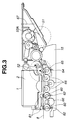
- a recording sheet 101 fed by a feeding roller (not shown) in the direction of an arrow A reaches and enters a wedge portion formed by a conveying roller 103, having a conveying gear 102 fixed on the shaft thereof, and pinch rollers 104.
- a conveying motor (not shown) is driven, whereby the recording sheet 101 is conveyed to a writing-start position by the conveying roller 103, and recording is performed by a recording head 113 which discharges ink droplets in accordance with data from a personal computer or the like.
- a carriage 113a for holding the recording head 113 is supported by a guide shaft 113c and a guide rail 111 (see FIG. 5) so as to slidable in the lateral direction of the recording sheet 101.
- the leading edge of the recording sheet 101 reaches discharging rollers 106a, serving as rotating members, and spurs 109, also serving as rotating members, along ribs 105a and 105b provided on a platen 105.
- the ribs 105a and 105b are disposed at positions on productions from corresponding discharging rollers 107a, serving as rotating members, and discharging rollers 106a, respectively, in order to prevent contact of respective portions of cockling of the recording sheet 101 (to be described later) to the ribs 105a and 105b, and rub between the recording head 113 and the recording sheet 101 raised due to strong stiffness caused by cockling.
- the ribs 105a and 105b have different start points 105a 1 and 105b 1 (see FIG. 5), in order to reduce load at the points 105a 1 when the ribs 105a and 105b contact the recording sheet 101 and the load torque of the conveying motor has the largest value because of the configuration of the path having an angle, when a thick recording sheet is conveyed.
- the distance between the recording head 113 and the recording sheet 101 until the recording sheet 101 reaches the discharging rollers 106a is determined by the height of the ribs 105a and 105b.
- the heights of the ribs 105a and 105b are set to such values that rub with the recording head 113 and the like, and jam of the recording sheet 101 are not produced due to warp of the recording sheet 101 and warp caused by a recording pattern.
- the leading edge of the recording sheet 101 depresses a discharging-roller shaft 106 and the discharging rollers 106a urged by compression springs 108 in the direction of the thickness, i.e., a direction substantially orthogonal to the conveying direction, of the sheet, reaches the discharging rollers 107a and spurs 110 while contacting ribs 105c, and is discharged while depressing a discharging-roller shaft 107 and the discharging rollers 107a.
- Each of the spurs 109 and 110 is formed by etching a thin stainless-steel plate in the shape of a gear, and has a plurality of radially formed teeth 110b which are in point contact or line contact with the sheet 101 at very small areas.
- the angle of the distal end of each tooth 110b is about 25° - 30°.
- the spurs 109 and 110 are mounted on spur shafts 109a and 110a, respectively, which are insertion formed using resin.
- the spur shaft 109a is slidably rotated by being urged against the plane of the guide rail 111, made of a metal plate, for guiding the carriage 113a by the discharging rollers 106a via compression springs 108. Accordingly, the distance between the recording sheet 101 and the recording head 113 is determined by the values of accuracy in respective components, and an adjusting mechanism, such as an adjusting lever or the like, for adjusting the distance between the recording sheet 101 and the recording head 113 is absent.
- the spur shaft 110a is slidably rotated in a bearing unit 112a of a spur holder 112 made of resin.
- the contact points between the spurs 110 and the recording sheet 101 are set to be higher than the contact points between the spurs 109 and the recording sheet 101.
- two sets of a discharging-roller train and a spur train are provided.
- FIG. 6 is a front view of the recording apparatus as seen from the discharging direction.
- An elastic portion 107b having a small diameter for allowing elastic deformation is formed on the discharging-roller shaft 107, made of resin, urged toward the spurs 110 by the compression springs 108.
- a driving force is transmitted to the shaft 107 via a gear 107d.
- an elastic portion 106b is formed in the discharging-roller shaft 106.
- a driving force is transmitted to the shaft 106 via a gear 106d.
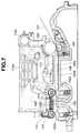
- FIG. 7 illustrates a state in which recording has been performed from the leading edge of the recording sheet 101, which reaches ribs 105c provided between the dicharging rollers 106a and 107a. Curl of the leading edge of the recording sheet 101 is grown toward the second surface of the recording sheet 101 caused by recording.
- FIG. 8 illustrates a behavior of the recording sheet 101 based on an experminent when ribs are absent between the discharging rollers 106a and 107b.
- the recording sheet 101 contacts the recording head 113 at a portion B.
- FIG. 7 illustrates a state in which the amount of curl is reduced due to the stiffness of the recording sheet 101. It has been experimentally confirmed that the recording sheet 101 does not contact the recording head 113 due to the above-described ribs 105c.
- the height of the rib 105c is set to be lower than the height of the line obtained by connecting the contact point between the spur 109 and the discharging roller 106a to the contact point between the spur 110 and the discharging roller 107a.
- FIGS. 9 and 10 illustrate states in which a very stiff sheet, such as a plastic film 114 or the like, is conveyed.
- a solid line on the platen 105 indicates a state of conveyance before the plastic film 114 reaches the discharging rollers 107a
- a dotted line indicates a state after the plastic fim 114 reaches the dicharging rollers 107a.
- a solid line indicates a state of conveyance of the plastic film 114 when ribs are absent between the discharging rollers 106a and 107a
- a dotted line indicates a state of conveyance when the plastic film 114 reaches the discharging rollers 107a.
- the distances c and d between the plastic film 114 and the recording head 113 which determine the recording quality, in the respective cases have the relationship of c ⁇ d.
- the rates of change c' and d' of the distances c and d have also the relationship of c' ⁇ d'. That is, the displacement in the distance when ribs are present is smaller than in the other case, and therefore higher-quality recording can be performed even with a stiff sheet.
- the rib 105c is disposed on the production between the discharging rollers 106a and 107a so as not to contact trough portions of cockling.
- the discharging-roller shaft 106 is urged by two compression springs 108 so as to be slidably rotatable, and the discharging-roller shaft 107 is urged by four compression springs 108 having the same spring constant as that of the above-described two compression springs 108.
- the load of the compression spring 108 is set to a low load value, in order to separate the discharging-roller shaft 106 from the recording head 113 due to the stiffness of cockling when the recording sheet 101 has cockling.
- the elastic portion 106b it is possible to unify the load applied to the discharging-roller shaft 106, to reduce the load applied to the spurs 109, and thereby to remove transfer traces of ink caused by the spurs 109.
- the values of pressure applied to the discharging-roller shafts 106 and 107 differ because of the following reasons.
- the distance between the recording sheet 101 and the recording head 113 is maintained constant, and the discharging-roller shaft 106 is separated from the recording head 113 if large cockling is present when recording image data by reducing the feeding pitch of the recording sheet 101, randomly dividing the image data, and increasing the number of scanning operations of the carriage 113a, in order to prevent contact between the recording head 113 and the recording sheet 101.
- the load of this region is set to a value higher than the value of the load of the region of the discharging-roller shaft 106, in order to prevent rub between the recording sheet 101 and the recording head 113 due to a raise of a heavy recording sheet, such as an envelope, a post card or the like, or a recording sheet whose weight has increased after high-duty-ratio recording when it leaves the conveying roller 103 and the pinch rollers 104, bending of the recording sheet 101 during recording, or rub between the recording sheet 101 and the recording head 113 due to such bending.
- a heavy recording sheet such as an envelope, a post card or the like
- compression springs 108 having the same configuration are used. Two compression springs 108 are provided for the discharging-roller shaft 106, and four compression springs 108 are provided for the discharging-roller shaft 107. In order to obtain desired spring loads, the surfaces for mounting the respective compression springs 108 have different heights.
- FIGS. 11 and 12 are schematic diagrams of the ink-jet recording apparatus as seen from above.
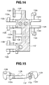
- FIGS. 14 and 15 are a plan view and a side view of the spur holder 112, respectively.
- each portion surrounded by dotted lines represents a unit comprising the spur holder 112 and the spurs 109 and 110.
- This recording apparatus is configured by eight such units.
- the spurs 109 are disposed at intervals of about less than 13 mm above the discharging-roller shaft 106.
- FIG. 13 illustrates a cross section taken along line B - B shown in FIG. 12. Bearings 112m (see FIG.
- the spur holder 112 is positioned by contact surfaces 112b and a contact surface 111a of the guide rail 111, and is anchored and fixed by notches 111b of the guide rail 111 and engaging portions 112c of the spur holder 112. That is, the lower surface of the guide rail 111 is made in contact with projections 112k, and the contact surfaces 112b and the engaging portions 112c are engaged with the upper surface of the guide rail 111.
- the distal end 112g of the regulating member has a smooth surface in order to prevent rub of ink at the edge, or the like. According to such a configuration, the distance H between the contact C between the spur 109 and the discharging roller 106a and the distal end 112g can be accurately set.
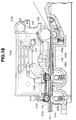
- FIG. 16 is a front view illustrating a state of cockling of the recording sheet 101 when the regulating members 112d are absent in the ink-jet recording apparatus of the present embodiment.
- An arrow D indicates the moving direction of the recording head 113, and a dotted line E present on its production indicates the locus of the recording head 113.
- Each hatched portion F indicates a region where a crest 101a of cockling contacts the recording head 113. In such a state, not only rub traces are produced in the obtained image, but also the recording head 113 is damaged, thereby shortening the life of the recoring head 113.
- FIG. 18 is a cross-sectional view taken along line G - G shown in FIG. 16.
- a surface 101b of the recording sheet 101 indicates the slope of the surface, on which recording is performed, of the recording sheet 101 undulated due to cockling.
- a surface 101c of the recording sheet 101 indicates the slope of the surface opposite to the surface 101b.
- the recording sheet 101 contacts the reording head 113 at a portion F.
- FIG. 19 is a cross-sectional view taken along line J - J shown in FIG. 17. Since the distance between the crest 101a of the recording sheet 101 due to cockling and the recording head 113 is limited by the distal end 112g at the spur holder 112, rub between the recording sheet 101 and the recording head 113 does not occur.
- the recording head 113 rubs the recording sheet 101 before ink dries, thereby disturbing the obtained image. If the distance H is too small, the size of cockling cannot be regulated, and therefore the recording sheet 101 rubs the recording head 113.
- the regulating member 112d is disposed in the vicinity of the spur 109, and the distance H is set to about 1mm which value has provided excellent results in experiments.
- Walls 112h having a size greater than the outer diameter of the spurs 109 and 110 are formed in the spur holder 112 so that, for example, the distal ends of the spurs 109 and 110 are not bent due to disturbance, and the distal ends of the teeth of the spurs 109 and 110 are not damaged.
- the regulating members may be separated from the spur holder. If the regulating member is made of water-repellent fluororesin, since rub traces are produced less frequently, the distance H can be reduced, and therefore the probability of occurrence of cockling can be reduced.
- the discharging rollers 106a and 107a are made of plastic resin.
- the discharging-roller shafts 106 and 107 comprise two-color moldings.
- the discharging-roller shaft 106, the discharging rollers 106 and the spurs 109 have the function of maintaining the distance between the recording sheet 101 and the recording head, and separating warp of the recording sheet due to cockling from the recording head.
- the interval between adjacent spurs 109 is set to about less than 13 mm, and 16 spurs 109 are provided in total.
- the interval between adjacent discharging rollers 106a is set to about 26 mm, and 8 discharging rollers 106a are provided in total. Accordingly, a spur 109 which is not urged by a discharging roller is disposed between two discharging rollers 106a.
- the interval between adjacent discharging rollers 106a is set to about 13 mm, a trough of the recording sheet 101 having a strong stiffness due to cockling cannot escape, and the recording sheet 101 is raised toward the recording head 113, thereby causing rub with the recording head 113.
- the discharging roller 106a having a large diameter is not provided below the spur 116.
- the discharging-roller shaft 107, the discharging rollers 107a having a large diameter, and the spurs 110 have the function of guiding the recording sheet 101, such as thick paper or the like, maintaining the distance between the recording sheet 101 and the recording head 113 against disturbance while the recording sheet 101 is discharged, and minimizing undulation of cockling.
- eight spurs 110 and sixteen discharging rollers 107a and 107c are provided in total, and the spurs 110 are urged with low load. Accordingly, the interval between adjacent spurs 110 is set to about 26 mm, and the interval between the center axes of the discharging rollers 107a and 107c is set to about 13 mm.
- the discharging roller 107c not facing the spur 110 is disposed on the production obtained by connecting the discharging roller 106a and the urging member of the spur 110, and the discharging roller 107a and the urging member of the spur 110 are dispoded on the production from the spur 116, which is not urged, in the direction of the recording-sheet conveying direction.
- a projection of cockling in the recording sheet 101 is downwardly regulated by the spur 109, and the recording sheet 101 curls toward its back at the region of the discharging roller 107c situated in the discharging direction. At that time, if the discharging roller 107a is absent, the recording sheet 101 falls in this region.
- the sheet 101 can be discharged with a discharging force lower than when a single discharging roller is used.
- the discharging roller 107c is made of plastic resin using two-color molding, it may be made of rubber. Furthermore, although in order to increase the discharging property, a member having a high coefficient of friction is used, the same material as for the shaft member may be used in order to prevent deflection of the recording sheet 101.
- FIG. 20 is a front view illustrating an ink-jet recording apparatus according to a second embodiment of the present invention. Although a method of engagement is not shown, a transmission gear unit 107d is fixed to a discharging-roller shaft 107 via a compression spring 114. By thus forming an elastic portion, it is possible to unify the discharging pressure, to provide a more stable period in cockling, and to obtain a high-quality image.
- FIG. 21 is a front view of an ink-jet recording apparatus according to a third embodiment of the present invention.
- the outer diameter of a discharging-roller shaft 115 is smaller than the outer diameter of the discharging-roller shaft 107 uniformly over the entire span. According to such a configuration, it is possible to unify the discharging pressure, and to reduce the sliding load at the regions of springs 108.
- FIG. 22 is a cross-sectional view illustrating an ink-jet recording apparatus according to a fourth embodiment of the present invention.
- a rib 105d disposed above a platen 105 comprises, for example, a spring member made of a thin plate, and forms an elastic member. According to such a configuration, the load torque applied to the motor described in the first embodiment can be reduced. Furthermore, by providing a movable rib 105e, the load torque applied to the discharging-roller shaft due to the thickness of the recording sheet 101 can be further reduced. Particularly, accuracy in recording after the recording sheet 101 has passed through a pinch roller 104 can be improved.
- the urging force of the discharging-roller spring 62 is determined so that it vertically moves in accordance with the behavior of the recording sheet 8. Accordingly, the pinch roller 57 and the discharging roller 60 is urged by the pinch-roller spring 59 and the discharging-roller spring 62 toward the conveying roller 52 and the spur 61 fixed to the chassis 50, respectively, and the pinch roller 57 and the discharging roller 60 vertically move in accordance with the thickness and the behavior of the recording sheet 8.
- the distance between the recording head 1 and the recording sheet 8 is constant, and therefore an adjusting lever for adjusting the distance between the recording head 1 and the recording sheet 8 or the like, which has been necessary in the conventional apparatus, becomes unnecessary.
- the spurs 61 are rotated by being driven by the discharging rollers 60, and can discharge the recording sheet 8.
- Two discharging rollers 60 are provided in order to prevent rub between the recording sheet 8 and the recording head 1 when conveying and discharging a stiff recording sheet, such as a post card, an envelope or the like, or a curled recording sheet.
- the drive transmission unit for the discharging rollers 60 is held at a left-end portion out of the recording-sheet conveying path on the base 15.
- the drive is transmitted from a discharging idle roller 65, which is in pressure contact with the conveying roller 52 by an idle-roller spring 64, to the discharging rollers 62 via an idle gear train 66.
- the conveying roller 52 rotates in the feeding direction (the direction of the arrow A)
- the drive is transmitted to the idle gear train 66 via the discharging idle roller 65, i.e., the discharging rollers 60 rotate.
- the discharging rollers 60 and their drive transmission unit are also held on the base 15.
- a cap member 9, made of an elastic material and capable of encapsulating the recording head 1, is made of an appropriate material, such as chlorinated butyl rubber or the like.
- the cap member 9 is integrally held on a cap holder 10.
- the cap holder 10 is rotatably held by an arm unit 11A integrally extending from a cylinder 11.
- the cylinder 11 incorporates a piston (not shown), and a negative pressure can be produced within the cylinder 11 by driving a piston shaft 13.
- the cap 9 includes a flexible joint portion 9A integrally formed therewith. By pushing the joint portion 9A into a joint portion 11B provided on the cylinder 11 with having an interference, the cylinder 11 and the cap 9 are connected together in a sealed state.
- the cap 9 integrally held by the cap holder 10 is hermetically connected to the cylinder 11, and the cap holder 10 is rotatably held by the arm unit 11A relative to the cylinder 11.
- a cap spring 14 is provided between the base 15 and the cap holder 10 so as to always urge the cap holder 10 toward the recording head 1.
- the cylinder 11 is supported by the base 15 so as to rotatable around a cylinder shaft.
- a rotating force around the cylinder shaft is provided for the cylinder 11 and the cap 9 by the cap spring 14.
- a cylinder control unit 11C is integrally formed on the cylinder 11, and the distal end of the cylinder control unit 11C contacts a cam portion 16A of a pump cam gear 16 rotatably held on the base 15.
- the rotation of the cylinder 11 is controlled by the cam portion 16A of the pump cam gear 16 via the cylinder control unit 11C. That is, by vertical movement of the cylinder control unit 11C along the cam portion 16A of the pump cam gear 16, the cap 9 can be capped on or removed from the recording head 1.
- the pump cam gear 16 and the driving transmission unit held by the base 15 are provided at right-end portions separated from the recording-sheet conveying path on the base 15.
- the pump cam gear 16 can be selectably connected to an LF gear 17 press fitted on the conveying roller 52.
- the pump cam gear 16 is connected to a cylinder cap gear 18.
- a boss 18A provided in the inner wall of the cylinder cap gear 18 in a lead groove (not shown) provided in the piston shaft 13, the rotating movement of the pump cam gear 16 is converted into the linear movement of the piston shaft 13.
- the cap 9 can be connected to the recording head 1 by pressure by providing the cap spring 14 between the base 15 and the cap holder 10. Accordingly, the recording head 1 is capped when recording is not performed, thereby preventing the nozzle from drying.
- the discharging operation can be returned to a normal state.
- Waste ink absorbed from the recording head 1 via the cap 9 by the above-described pumping mechanism enters the cylinder 11, and is discharged from a cylinder end 11D by the movement of a pistion (not shown).
- the cylinder end 11D is inserted in the base 15, and is rotably held by the base 15.
- a cylinder absorbing member 19 is inserted in the cylinder end 11D from which waste ink is discharged. Since the cylinder absorbing member 19 must have a property of efficiently discharging waste ink present within the cylinder 11 to the outside, a material having an excellent ink-transfer property, such as a foam sponge, is selected. As shown in FIGS. 2 and 23, the cylinder absorbing member 19 is surrounded by, i.e,, in pressure contact with, waste-ink absorbing members 20, 21 and 22 within the base 15.
- waste ink within the cylinder 11 is transferred from the cylinder absorbing member 19 to the waste-ink absorbing members 21, 22 and 23.
- a material having a high ink-holding property such as a laminated sheet of paper or a high-molecular material, is selected for the waste-ink absorbing members 20, 21, 22 and 23. As shown in FIG. 2, the waste-ink absorbing members 20, 21, 22 and 23 are held within the base 15. Since the base 15 includes the pinch-roller unit and the discharging-roller unit, it does not have a uniform cross section.
- a pulp material is mostly used for the waste-ink absorbing member from the viewpoint of the cost and the absorption property, and is formed using cutting dies. Accordingly, a plurality of waste-ink absorbing members are accommodated within the base 15 in order to efficiently dispose the members within the base 15 and to secure a large capacity for waste ink.
- the cylinder absorbing member 19 is disposed in pressure contact with the waste-ink absorbing members 20, 21 and 22. According to such arrangement, the cylinder absorbing member 19 is fixed by being surrounded by the members 20, 21 and 22. Hence, the cylinder absorbing member 19 is prevented from leaving the cylinder 11, and therefore ink does not leak.
- waste-ink absorbing members As described above, four waste-ink absorbing members are used and accomodated within the base 15. However, if these members are used as a base unit, they tend to leave the base 15. Accordingly, as shown in FIG. 2, after accommodating the waste-ink absorbing members within the base 15, a waste-ink seal 24 covers these members as a cap.
- the waste-ink seal 24 comprises a transparent polyethylene sheet, so that the waste-ink absorbing members accommodated within the base 15 can be seen from the back of the base 15.
- the waste-ink absorbing members 20, 21, 22 and 23, and the cylinder absorbing member 19 can be visually checked from the side of the waste-ink seal 24.
- a hole 20A is provided in the absorbing member 20, so that the cylinder absorbing member 19 present within the case 15 can be visually confirmed.
- all of the absorbing members can be seen from the outside in the state of units by providing the transparent waste-ink seal 24.
- the base 15 holds the pumping mechanism, the pinch-roller unit, the sheet-discharging unit and the waste-ink absorbing members, as well as the sheet-feeding stack unit, the separation means and the drive transmission unit. These components constitute a base unit.
- the chassis unit comprises the conveying roller 52, the carriage guide shaft 3 and the feeding-roller shaft 53 fixted to the chassis 50, the guide rail 4 holding the carriage 2 ad the spurs 61, and the like.
- the printer unit is configured by assembling the base unit shown in the upper portion of FIG. 26, and the chassis unit shown in the lower portion of the FIG. 26.
- the base unit and the chassis unit are combined together by fitting a boss 15A provided on the base 15 in an engaging groove 50A provided in the chassis 50, and engaging a pawl 15B provided on the base 15 in a hole 50B provided in the chassis 50 by rotating the chassis unit around the boss 15A, to provide the printer unit shown in FIG. 1.
- the pinch roller 57 held on the base unit 15 is urged toward the conveying roller 52 by the spring
- the discharging idle roller 65 is elastically urged toward the conveying roller 52
- the discharging rollers 60 are urged toward the spurs 61 by the springs
- the cap 9 used for maintaining and recovering the ink discharge stability of the recording head 1 is elastically urged toward the recording head 1 mounted on the carriage 2 (not shown in FIG. 26, see FIGS. 1 and 2) at a head home position.
- urging of components by springs at the contact portion are realized using coil springs, plate springs, molded springs or the like may also be used. Furthermore, printing members at at least one of the units may be elastically urged.
- the present invention has been described illustrating a printer in which an ink-jet recording head is mounted on a carriage.
- the present invention may also be applied to an information processing apparatus which, for example, includes a scanner unit comprising a recording head having sustantially the same external shape as the ink-jet recording head that can be compatibly mounted on a carriage, and which can read image information from a sheet of an original supported on a platen.
- the size and the weight of the apparatus can be reduced by providing springs at contact portions of at least one of the units so that contact portions between the printing members disposed on the chassis unit and the printing members disposed on the base unit except engaging portions for combining the two units are urged by the springs when the two units are combined together. Furthermore, by reducing the number of components, accumulated tolerance of the entire apparatus is reduced, the generation of backlash caused by poor accuracy in positioning is thereby reduced, the feeding/discharging property, the conveying property and the capping property of the apparatus are improved, and the assembling capability is greatly improved.
- stepless adjustment of the distance between the recording sheet and the recording head can be realized and the size of the apparatus can be reduced.
- the apparatus includes a first roller for conveying the sheet member toward a supporting surface, a second roller for grasping the sheet member together with the first roller, a third roller for discharging the sheet member from the supporting surface, and a fourth roller for grasping the sheet member togetherwith the third roller.
- the apparatus also includes a first case including a carriage, the first roller and the third roller, and a second case including a platen, the second roller and the fourth roller. The second roller is elastically urged toward the first roller, and the fourth roller is elastically urged toward the third roller.
Landscapes
- Ink Jet (AREA)
- Handling Of Cut Paper (AREA)
- Delivering By Means Of Belts And Rollers (AREA)
Applications Claiming Priority (6)
| Application Number | Priority Date | Filing Date | Title |
|---|---|---|---|
| JP3126295 | 1995-02-21 | ||
| JP32194/95 | 1995-02-21 | ||
| JP3126295 | 1995-02-21 | ||
| JP3219495 | 1995-02-21 | ||
| JP31262/95 | 1995-02-21 | ||
| JP3219495 | 1995-02-21 |
Publications (3)
| Publication Number | Publication Date |
|---|---|
| EP0728589A2 true EP0728589A2 (de) | 1996-08-28 |
| EP0728589A3 EP0728589A3 (de) | 1998-07-22 |
| EP0728589B1 EP0728589B1 (de) | 2004-06-23 |
Family
ID=26369721
Family Applications (1)
| Application Number | Title | Priority Date | Filing Date |
|---|---|---|---|
| EP96102537A Expired - Lifetime EP0728589B1 (de) | 1995-02-21 | 1996-02-20 | Aufzeichnungsgerät |
Country Status (3)
| Country | Link |
|---|---|
| US (1) | US5847719A (de) |
| EP (1) | EP0728589B1 (de) |
| DE (1) | DE69632757T2 (de) |
Cited By (3)
| Publication number | Priority date | Publication date | Assignee | Title |
|---|---|---|---|---|
| EP1160088A3 (de) * | 2000-05-31 | 2002-04-10 | Seiko Epson Corporation | Punktaufzeichnungsgerät |
| US6659603B2 (en) * | 1999-05-14 | 2003-12-09 | Canon Kabushiki Kaisha | Ink jet recording method and apparatus having platen with extrusions positioned in one-to-one correspondence with roller nips |
| EP1705022A3 (de) * | 2005-03-25 | 2010-03-17 | Canon Kabushiki Kaisha | Bildformungsverfahren und -gerät |
Families Citing this family (31)
| Publication number | Priority date | Publication date | Assignee | Title |
|---|---|---|---|---|
| US6619795B1 (en) * | 1993-11-10 | 2003-09-16 | Canon Kabushiki Kaisha | Ink jet recording apparatus |
| US6196672B1 (en) * | 1997-06-27 | 2001-03-06 | Brother Kogyo Kabushiki Kaisha | Hot-melt type ink jet printer having heating and cooling arrangement |
| JP3697059B2 (ja) | 1998-04-15 | 2005-09-21 | キヤノン株式会社 | 画像形成装置 |
| US6644801B2 (en) | 1999-12-27 | 2003-11-11 | Canon Kabushiki Kaisha | Ink jet recording apparatus |
| US6786663B2 (en) * | 2000-07-17 | 2004-09-07 | Canon Kabushiki Kaisha | Recording apparatus |
| US6557961B2 (en) | 2001-06-22 | 2003-05-06 | Canon Kabushiki Kaisha | Variable ink firing frequency to compensate for paper cockling |
| US6604803B1 (en) | 2000-09-12 | 2003-08-12 | Canon Kabushiki Kaisha | Printer which compensates for paper unevenness |
| US6979080B2 (en) * | 2001-08-29 | 2005-12-27 | Brother Kogyo Kabushiki Kaisha | Printer having improved recording medium feeding mechanism |
| JP4073008B2 (ja) * | 2002-09-17 | 2008-04-09 | キヤノン株式会社 | 記録装置 |
| KR100472479B1 (ko) * | 2002-10-31 | 2005-03-08 | 삼성전자주식회사 | 잉크젯 프린터의 용지 가이드 및 그를 구비한 잉크젯 프린터 |
| US20060285450A1 (en) * | 2002-11-06 | 2006-12-21 | Low Yee C | Optical disc drive apparatus, method of controlling the position of optical pickup unit, method of detecting an innermost positon of an optical pickup unit |
| JP4078218B2 (ja) * | 2003-01-31 | 2008-04-23 | キヤノン株式会社 | 記録装置 |
| JP4501373B2 (ja) * | 2003-02-17 | 2010-07-14 | 富士ゼロックス株式会社 | 記録装置 |
| JP3694006B2 (ja) * | 2003-05-21 | 2005-09-14 | シャープ株式会社 | インクジェットプリンタ |
| JP2005089125A (ja) * | 2003-09-18 | 2005-04-07 | Ricoh Co Ltd | 画像形成装置 |
| JP2005247476A (ja) * | 2004-03-03 | 2005-09-15 | Ricoh Co Ltd | 画像形成装置 |
| JP4560336B2 (ja) * | 2004-06-14 | 2010-10-13 | キヤノン株式会社 | 記録装置 |
| US7654635B2 (en) * | 2004-11-15 | 2010-02-02 | Hewlett-Packard Development Company, L.P. | Media print system |
| US7287922B2 (en) * | 2005-03-03 | 2007-10-30 | Lexmark International, Inc. | Exit roller system for an imaging apparatus including backup rollers configured to reduce tracking |
| US20070201933A1 (en) * | 2006-02-24 | 2007-08-30 | Park Namjeon | Feeding system for image forming machine |
| JP2008036906A (ja) * | 2006-08-03 | 2008-02-21 | Brother Ind Ltd | インクジェットプリンタ |
| JP2008246879A (ja) * | 2007-03-30 | 2008-10-16 | Brother Ind Ltd | 画像記録装置 |
| JP2011062989A (ja) * | 2009-09-18 | 2011-03-31 | Fujifilm Corp | 記録装置 |
| JP6115128B2 (ja) | 2012-03-30 | 2017-04-19 | ブラザー工業株式会社 | インクジェットプリンタのギャップ情報取得方法、インクジェットプリンタ、及び、液体吐出装置 |
| JP6032003B2 (ja) | 2012-03-30 | 2016-11-24 | ブラザー工業株式会社 | インクジェットプリンタ、インクジェットプリンタのギャップ情報取得方法、及び、液体吐出装置 |
| JP6028565B2 (ja) | 2012-03-30 | 2016-11-16 | ブラザー工業株式会社 | インクジェットプリンタ、インクジェットプリンタのギャップ情報取得方法、及び、液体吐出装置 |
| US8882215B2 (en) | 2012-03-30 | 2014-11-11 | Brother Kogyo Kabushiki Kaisha | Method and inkjet printer for acquiring gap information |
| JP5803785B2 (ja) | 2012-03-30 | 2015-11-04 | ブラザー工業株式会社 | インクジェットプリンタ |
| JP7271282B2 (ja) | 2019-04-15 | 2023-05-11 | キヤノン株式会社 | インクジェット記録装置、制御方法、およびプログラム |
| JP7301584B2 (ja) | 2019-04-15 | 2023-07-03 | キヤノン株式会社 | 画像処理装置、画像処理方法、およびプログラム |
| JP7309427B2 (ja) | 2019-04-15 | 2023-07-18 | キヤノン株式会社 | インクジェット記録装置、記録方法、およびプログラム |
Family Cites Families (15)
| Publication number | Priority date | Publication date | Assignee | Title |
|---|---|---|---|---|
| US4168058A (en) * | 1977-11-30 | 1979-09-18 | Ncr Corporation | Record member feeding device |
| US4279413A (en) * | 1979-10-17 | 1981-07-21 | Burroughs Corporation | Drive mechanisms for passbooks |
| JPS58187384A (ja) * | 1982-04-28 | 1983-11-01 | Canon Inc | 印字装置 |
| US4478402A (en) * | 1983-02-07 | 1984-10-23 | Eastman Kodak Company | Nip drive for sheet feeding apparatus |
| JPS5957777A (ja) * | 1983-08-26 | 1984-04-03 | Hitachi Ltd | 帳票送り装置 |
| JPS60112470A (ja) * | 1983-11-24 | 1985-06-18 | Canon Inc | 紙送り装置 |
| US5019839A (en) * | 1986-12-25 | 1991-05-28 | Canon Kabushiki Kaisha | Recording apparatus having a movable sheet guide member |
| US5291224A (en) * | 1989-10-27 | 1994-03-01 | Canon Kabushiki Kaisha | Sheet feeding apparatus using pairs of spur rollers |
| AT393654B (de) * | 1989-10-30 | 1991-11-25 | Engel Kurt | Einrichtung zum beschriften |
| US5225853A (en) * | 1990-02-02 | 1993-07-06 | Canon Kabushiki Kaisha | Recording apparatus with conveyor cleaning mechanism |
| US5602571A (en) * | 1990-03-14 | 1997-02-11 | Canon Kabushiki Kaisha | Sheet feeding apparatus and recording system with it |
| JP2875915B2 (ja) * | 1991-08-02 | 1999-03-31 | キヤノン株式会社 | 記録装置 |
| US5358230A (en) * | 1992-04-24 | 1994-10-25 | Canon Kabushiki Kaisha | Sheet supplying apparatus |
| ATE208279T1 (de) * | 1992-07-31 | 2001-11-15 | Canon Kk | Blattfördervorrichtung |
| US5793399A (en) * | 1993-12-27 | 1998-08-11 | Canon Kabushiki Kaisha | Sheet supplying apparatus |
-
1996
- 1996-02-16 US US08/602,357 patent/US5847719A/en not_active Expired - Fee Related
- 1996-02-20 EP EP96102537A patent/EP0728589B1/de not_active Expired - Lifetime
- 1996-02-20 DE DE69632757T patent/DE69632757T2/de not_active Expired - Lifetime
Cited By (4)
| Publication number | Priority date | Publication date | Assignee | Title |
|---|---|---|---|---|
| US6659603B2 (en) * | 1999-05-14 | 2003-12-09 | Canon Kabushiki Kaisha | Ink jet recording method and apparatus having platen with extrusions positioned in one-to-one correspondence with roller nips |
| EP1160088A3 (de) * | 2000-05-31 | 2002-04-10 | Seiko Epson Corporation | Punktaufzeichnungsgerät |
| US6655864B2 (en) | 2000-05-31 | 2003-12-02 | Seiko Epson Corporation | Dot recording apparatus |
| EP1705022A3 (de) * | 2005-03-25 | 2010-03-17 | Canon Kabushiki Kaisha | Bildformungsverfahren und -gerät |
Also Published As
| Publication number | Publication date |
|---|---|
| US5847719A (en) | 1998-12-08 |
| EP0728589A3 (de) | 1998-07-22 |
| DE69632757T2 (de) | 2005-07-07 |
| DE69632757D1 (de) | 2004-07-29 |
| EP0728589B1 (de) | 2004-06-23 |
Similar Documents
| Publication | Publication Date | Title |
|---|---|---|
| US5847719A (en) | Recording apparatus | |
| EP0581276B1 (de) | Blattfördervorrichtung | |
| US8109585B2 (en) | Recording apparatus | |
| US7992869B2 (en) | Sheet-conveying device | |
| EP0518255A2 (de) | Automatische Blattzuführvorrichtung mit Schrägstellungskorrektur | |
| US8727468B2 (en) | Recording apparatus | |
| JP3595779B2 (ja) | 記録装置 | |
| US6168260B1 (en) | Recording apparatus | |
| EP1803670B1 (de) | Bogenzuführeinrichtung | |
| EP1803574B1 (de) | Tintenstrahlaufzeichnungsvorrichtung und Treibereinheit darin | |
| JP3548554B2 (ja) | 記録装置 | |
| US8622381B2 (en) | Sheet supply apparatus | |
| US6416050B1 (en) | Auto sheet feeder | |
| JP3507236B2 (ja) | 記録装置 | |
| JP3359205B2 (ja) | 記録装置 | |
| US7204483B2 (en) | Sheet media input tray | |
| JPH10250184A (ja) | 記録装置 | |
| US7331728B2 (en) | Printer having a platen | |
| JP2006076029A (ja) | 記録装置及び記録装置の制御方法 | |
| JP2006044060A (ja) | 記録装置 | |
| JP2006043893A (ja) | 記録装置 | |
| JP2001199568A (ja) | 給紙装置及びこれを備えた画像形成装置 | |
| JPS6114948B2 (de) | ||
| JP2002087599A (ja) | 用紙エッジガイド,給紙カセット,給紙装置,記録装置 | |
| JPH06127714A (ja) | 給紙装置及び記録装置 |
Legal Events
| Date | Code | Title | Description |
|---|---|---|---|
| PUAI | Public reference made under article 153(3) epc to a published international application that has entered the european phase |
Free format text: ORIGINAL CODE: 0009012 |
|
| AK | Designated contracting states |
Kind code of ref document: A2 Designated state(s): DE FR GB IT |
|
| PUAL | Search report despatched |
Free format text: ORIGINAL CODE: 0009013 |
|
| AK | Designated contracting states |
Kind code of ref document: A3 Designated state(s): DE FR GB IT |
|
| 17P | Request for examination filed |
Effective date: 19981208 |
|
| 17Q | First examination report despatched |
Effective date: 20000524 |
|
| GRAP | Despatch of communication of intention to grant a patent |
Free format text: ORIGINAL CODE: EPIDOSNIGR1 |
|
| GRAS | Grant fee paid |
Free format text: ORIGINAL CODE: EPIDOSNIGR3 |
|
| GRAA | (expected) grant |
Free format text: ORIGINAL CODE: 0009210 |
|
| AK | Designated contracting states |
Kind code of ref document: B1 Designated state(s): DE FR GB IT |
|
| PG25 | Lapsed in a contracting state [announced via postgrant information from national office to epo] |
Ref country code: IT Free format text: LAPSE BECAUSE OF FAILURE TO SUBMIT A TRANSLATION OF THE DESCRIPTION OR TO PAY THE FEE WITHIN THE PRE;WARNING: LAPSES OF ITALIAN PATENTS WITH EFFECTIVE DATE BEFORE 2007 MAY HAVE OCCURRED AT ANY TIME BEFORE 2007. THE CORRECT EFFECTIVE DATE MAY BE DIFFERENT FROM THE ONE RECORDED.SCRIBED TIME-LIMIT Effective date: 20040623 Ref country code: FR Free format text: LAPSE BECAUSE OF FAILURE TO SUBMIT A TRANSLATION OF THE DESCRIPTION OR TO PAY THE FEE WITHIN THE PRESCRIBED TIME-LIMIT Effective date: 20040623 |
|
| REG | Reference to a national code |
Ref country code: GB Ref legal event code: FG4D |
|
| REF | Corresponds to: |
Ref document number: 69632757 Country of ref document: DE Date of ref document: 20040729 Kind code of ref document: P |
|
| PLBE | No opposition filed within time limit |
Free format text: ORIGINAL CODE: 0009261 |
|
| STAA | Information on the status of an ep patent application or granted ep patent |
Free format text: STATUS: NO OPPOSITION FILED WITHIN TIME LIMIT |
|
| 26N | No opposition filed |
Effective date: 20050324 |
|
| EN | Fr: translation not filed | ||
| PGFP | Annual fee paid to national office [announced via postgrant information from national office to epo] |
Ref country code: GB Payment date: 20100219 Year of fee payment: 15 Ref country code: DE Payment date: 20100228 Year of fee payment: 15 |
|
| GBPC | Gb: european patent ceased through non-payment of renewal fee |
Effective date: 20110220 |
|
| REG | Reference to a national code |
Ref country code: DE Ref legal event code: R119 Ref document number: 69632757 Country of ref document: DE Effective date: 20110901 |
|
| PG25 | Lapsed in a contracting state [announced via postgrant information from national office to epo] |
Ref country code: GB Free format text: LAPSE BECAUSE OF NON-PAYMENT OF DUE FEES Effective date: 20110220 |
|
| PG25 | Lapsed in a contracting state [announced via postgrant information from national office to epo] |
Ref country code: DE Free format text: LAPSE BECAUSE OF NON-PAYMENT OF DUE FEES Effective date: 20110901 |