EP0728693B1 - Vorrichtung zum Transport einer Bahn durch Stationen einer Arbeitsanlage - Google Patents
Vorrichtung zum Transport einer Bahn durch Stationen einer Arbeitsanlage Download PDFInfo
- Publication number
- EP0728693B1 EP0728693B1 EP96100799A EP96100799A EP0728693B1 EP 0728693 B1 EP0728693 B1 EP 0728693B1 EP 96100799 A EP96100799 A EP 96100799A EP 96100799 A EP96100799 A EP 96100799A EP 0728693 B1 EP0728693 B1 EP 0728693B1
- Authority
- EP
- European Patent Office
- Prior art keywords
- web
- stations
- tape
- carrier tape
- holes
- Prior art date
- Legal status (The legal status is an assumption and is not a legal conclusion. Google has not performed a legal analysis and makes no representation as to the accuracy of the status listed.)
- Expired - Lifetime
Links
Images
Classifications
-
- B—PERFORMING OPERATIONS; TRANSPORTING
- B65—CONVEYING; PACKING; STORING; HANDLING THIN OR FILAMENTARY MATERIAL
- B65H—HANDLING THIN OR FILAMENTARY MATERIAL, e.g. SHEETS, WEBS, CABLES
- B65H39/00—Associating, collating, or gathering articles or webs
- B65H39/16—Associating two or more webs
-
- B—PERFORMING OPERATIONS; TRANSPORTING
- B65—CONVEYING; PACKING; STORING; HANDLING THIN OR FILAMENTARY MATERIAL
- B65H—HANDLING THIN OR FILAMENTARY MATERIAL, e.g. SHEETS, WEBS, CABLES
- B65H20/00—Advancing webs
- B65H20/06—Advancing webs by friction band
- B65H20/08—Advancing webs by friction band to effect step-by-step advancement of web
-
- B—PERFORMING OPERATIONS; TRANSPORTING
- B65—CONVEYING; PACKING; STORING; HANDLING THIN OR FILAMENTARY MATERIAL
- B65H—HANDLING THIN OR FILAMENTARY MATERIAL, e.g. SHEETS, WEBS, CABLES
- B65H20/00—Advancing webs
- B65H20/10—Advancing webs by a feed band against which web is held by fluid pressure, e.g. suction or air blast
-
- B—PERFORMING OPERATIONS; TRANSPORTING
- B65—CONVEYING; PACKING; STORING; HANDLING THIN OR FILAMENTARY MATERIAL
- B65H—HANDLING THIN OR FILAMENTARY MATERIAL, e.g. SHEETS, WEBS, CABLES
- B65H23/00—Registering, tensioning, smoothing or guiding webs
- B65H23/02—Registering, tensioning, smoothing or guiding webs transversely
-
- B—PERFORMING OPERATIONS; TRANSPORTING
- B65—CONVEYING; PACKING; STORING; HANDLING THIN OR FILAMENTARY MATERIAL
- B65H—HANDLING THIN OR FILAMENTARY MATERIAL, e.g. SHEETS, WEBS, CABLES
- B65H2701/00—Handled material; Storage means
- B65H2701/10—Handled articles or webs
- B65H2701/19—Specific article or web
- B65H2701/1912—Banknotes, bills and cheques or the like
Definitions
- the present invention relates to an apparatus for transporting a web through a plurality of stations of a working plant according to the preamble of claim 1.
- the material web is transported through a plurality of working stations, for example printing stations, milling stations for milling a recess into which a chip is to be embedded, punching stations and the like.
- the web has a width exceeding that used for the cards, and the excess margins are provided series of holes, the series extending parallel to the transportation direction, and the holes being spaced from one another by accurately repeated distances.
- pins engage into the holes so as to hold the web portion between the pins in a tensioned state.
- the web is stepwisely transported from station to station by means of clamps which do not engage the holes but hold the web in a pinching operation.
- the material consumption is higher than necessary because of the margins to be provided for the series of holes thereby increasing the costs of manufacture, in particular if expensive materials as e.g. poly carbonate are used.
- the tensioning systems provided at each station for the web render the plant complex, susceptible to trouble, and the distance between stations must be larger than necessary for the very working.
- US-A-4 810 006 discloses an adhesive coating to the secondary layer of the carrier material. Such an adhesive coating on the carrier material is a part of the carrier material.
- the apparatus of the present invention is defined in the characterizing part of claim 1.
- the width of the web from which cards are to be produced need not exceed that necessary for the cards themselves as the lateral perforated margin is provided on the tape.
- the tape may be tensioned over all stations by one single tensioning means so that the stations need not have such means.
- the tape may be made of a material which resists the working environment. Steel is preferred but plastic, e.g. polyester, may be suited as well. Perforation of a steel tape may be performed with extreme precision before the tape is closed to form the loop by, e.g. plasma welding.
- the displacement means preferably comprises drums having circumferentially disposed sprockets in engagement with the carrier tape holes.
- the carrier tape preferably is looped around a first driving drum and a second driven drum, and the distance spacing the drum axes defines the tension of the tape.
- the axis of the driving drum is stationary while the axis of the driven drum is displaceable so that the distance between the axes may be varied in order to adjust the tape tension.
- tension adjustment may be advisable in response to temperature variations.
- various other reasons may cause variation of the tape tension so that it is preferred to control the tension in response to the measured distance between adjacent holes.
- stepping motors drive the sprocket drum in order to displace the carrier tape by a predetermined stroke.
- the engagement between the sprockets and the holes provides for an unambigous relation between the number of pulses supplied to the stepping motor and the stroke through which the carrier tape is displaced.
- the "web” may consist of a series of cards already stamped from a substrate or laminate.
- the invention is applicable to webs of plastic as well as webs made of cardboard.
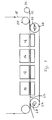
- the working stations 10, 12, 14, 16 are only schematically indicated. They may be four printing stations, one for each of the colors red, blue, yellow and one for black.
- the substrate web 18 to be printed on passes over a guiding drum 20 towards carrier tape 22 which surrounds a driving drum 24 and a driven drum 26.
- the drums rotate in accordance with arrow 28, driven by a stepping motor (not shown).
- Driven drum 26 is displaceable in direction of arrow 30 in response to ambien temperature variations.
- a strip 32 of plastic is coated on both of its faces with an adhesive or bonding material.
- the strip is wound on bobbin 34 and fed between web 18 and carrier tape 22. Downstream of station 10, the strip is released from both carrier tape 22 and web 18 and is discarded.
- a plurality of narrow ribbons may be used.
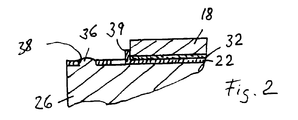
- Fig. 2 is a partial section view of the driven drum 26 having sprockets 36 in engagement with holes 38 of tape 22.
- the web 18 is held on carrier tape 22 by small upstanding stampings 39 cut from tape 22 and angled upwards.
Landscapes
- Physics & Mathematics (AREA)
- Fluid Mechanics (AREA)
- Advancing Webs (AREA)
- Credit Cards Or The Like (AREA)
- Processing And Handling Of Plastics And Other Materials For Molding In General (AREA)
- Folding Of Thin Sheet-Like Materials, Special Discharging Devices, And Others (AREA)
Claims (6)
- Vorrichtung zum Transportieren einer Bahn (18) durch mehrere Stationen (10, 12, 14, 16) einer Bearbeitungsanlage, umfassend:dadurch gekennzeichnet, daßein Trägerband (22), das durch die Stationen (10, 12, 14, 16) verläuft und eine geschlossene Schleife bildet,mindestens eine Reihe von Löchern (38), die in Längsrichtung des Bandes (22) um gleichmäßige Strecken beabstandet sind,Einrichtungen (24, 26, 36) zum schrittweisen Vorschieben des Trägerbandes (22) durch Zusammenwirkung mit den Löchern (38),Einrichtungen zum Halten der Bahn (18) auf einer Seite des Trägerbandes (22),die Einrichtungen zum Halten einen Streifen (32) mit zwei Hauptseiten, wovon jede mit einem Klebe-Haftmittel versehen ist, umfassen,Einrichtungen (34) vorgesehen sind, die den Streifen (32) vor den Stationen (10, 12, 14, 16) zwischen das Trägerband (22) und die Bahn (18) befördern, unddas Haftmittel so gewählt ist, daß es hinter den Stationen (10, 12, 14, 16) vom Trägerband (22) und von der Bahn (18) lösbar ist.
- Vorrichtung nach Anspruch 1, wobei das Band (22) aus einem Material hergestellt ist, das aus der Stahl und Kunststoff umfassenden Gruppe gewählt ist.
- Vorrichtung nach Anspruch 1, wobei die Einrichtungen (24, 26, 36) zum Verschieben Trommeln (24, 26) umfassen, wovon wenigstens eine in Umfangsrichtung angeordnete Kettenrad-Zähne (36), die mit den Bandlöchern (38) in Eingriff sind, enthält.
- Vorrichtung nach Anspruch 3, wobei das Trägerband (22) zwischen zwei Trommeln (24, 26) unter Zug gehalten wird.
- Vorrichtung nach Anspruch 4, wobei der Zug einstellbar ist.
- Vorrichtung nach Anspruch 5, wobei der Zug in Abhängigkeit von den Temperaturänderungen einstellbar ist.
Applications Claiming Priority (2)
| Application Number | Priority Date | Filing Date | Title |
|---|---|---|---|
| DE19506194A DE19506194A1 (de) | 1995-02-23 | 1995-02-23 | Vorrichtung zum Fördern einer Bahn durch Stationen einer Anlage |
| DE19506194 | 1995-02-23 |
Publications (3)
| Publication Number | Publication Date |
|---|---|
| EP0728693A2 EP0728693A2 (de) | 1996-08-28 |
| EP0728693A3 EP0728693A3 (de) | 1997-04-16 |
| EP0728693B1 true EP0728693B1 (de) | 2000-07-12 |
Family
ID=7754770
Family Applications (1)
| Application Number | Title | Priority Date | Filing Date |
|---|---|---|---|
| EP96100799A Expired - Lifetime EP0728693B1 (de) | 1995-02-23 | 1996-01-20 | Vorrichtung zum Transport einer Bahn durch Stationen einer Arbeitsanlage |
Country Status (3)
| Country | Link |
|---|---|
| EP (1) | EP0728693B1 (de) |
| JP (1) | JPH08268606A (de) |
| DE (2) | DE19506194A1 (de) |
Families Citing this family (3)
| Publication number | Priority date | Publication date | Assignee | Title |
|---|---|---|---|---|
| DE19723749A1 (de) * | 1997-06-06 | 1998-12-10 | Koenig & Bauer Albert Ag | Verfahren und Vorrichtung zum Quertrennen von laufenden Bedruckstoffbahnen |
| DE10009188A1 (de) * | 2000-02-26 | 2001-08-30 | Voith Paper Patent Gmbh | Vakuum-Bandfördervorrichtung |
| ATE315125T1 (de) | 2000-02-26 | 2006-02-15 | Voith Paper Patent Gmbh | Unterdruck-bandförderer |
Family Cites Families (5)
| Publication number | Priority date | Publication date | Assignee | Title |
|---|---|---|---|---|
| US1610818A (en) * | 1925-01-31 | 1926-12-14 | Spadone Machine Company Inc | Feeding mechanism |
| DE2949685A1 (de) * | 1979-12-11 | 1981-06-19 | Focke & Co, 2810 Verden | Vorrichtung zum herstellen von packungszuschnitten durch abtrennen von einer fortlaufenden bahn |
| DE3373289D1 (en) * | 1983-07-01 | 1987-10-08 | Roland Melzer | Method of producing plastic cards |
| US4810006A (en) * | 1987-05-26 | 1989-03-07 | Katz Marcella M | Stabilized sheet materials for use with computer-directed printers and method of stabilizing same for computer printers |
| JPH06220781A (ja) * | 1993-01-28 | 1994-08-09 | Kanebo Ltd | 捺染方法および装置 |
-
1995
- 1995-02-23 DE DE19506194A patent/DE19506194A1/de not_active Withdrawn
-
1996
- 1996-01-20 DE DE69609215T patent/DE69609215T2/de not_active Expired - Fee Related
- 1996-01-20 EP EP96100799A patent/EP0728693B1/de not_active Expired - Lifetime
- 1996-02-19 JP JP8030597A patent/JPH08268606A/ja active Pending
Also Published As
| Publication number | Publication date |
|---|---|
| EP0728693A3 (de) | 1997-04-16 |
| DE19506194A1 (de) | 1996-08-29 |
| DE69609215D1 (de) | 2000-08-17 |
| EP0728693A2 (de) | 1996-08-28 |
| DE69609215T2 (de) | 2001-03-08 |
| JPH08268606A (ja) | 1996-10-15 |
Similar Documents
| Publication | Publication Date | Title |
|---|---|---|
| US5750192A (en) | Method of producing linerless thermal labels | |
| US5017257A (en) | Variable length die cutter and method of cutting composite label | |
| NZ504357A (en) | Apparatus for variable image printing on adhesive tape using thermal print head | |
| DE69111284T2 (de) | Druckvorrichtung. | |
| EP0812664B1 (de) | Vorrichtung und Verfahren zum Perforieren von durchlaufendem Material und Vorrichtung und Verfahren zum Bearbeiten und Befestigen von photographischem Filmmaterial | |
| EP0728693B1 (de) | Vorrichtung zum Transport einer Bahn durch Stationen einer Arbeitsanlage | |
| HK82895A (en) | Paper feeding device | |
| DE10106949A1 (de) | Drucker zur Erzeugung einer Abbildung auf einer transportierten Bahn | |
| US5873966A (en) | Magnetic splice detection system | |
| US5239902A (en) | Method and apparatus for processing sheets of material in register, in particular for making security threads | |
| EP0726219B1 (de) | Verfahren zum Herstellen von Kunststoffkarten | |
| CA2226225A1 (en) | Integrated circuit chip card and the method and system for the manufacture of same | |
| US4443287A (en) | Method of manipulating printed products and means and apparatus for performance thereof | |
| US5893958A (en) | De-tackified continuous extrusion process applied integrated label product | |
| US6652698B1 (en) | Method and installation for manufacturing personalized coupons | |
| EP3923194B1 (de) | Kartenherstellungsverfahren | |
| EP4265364A1 (de) | Anlage und verfahren zum laserritzen und laminieren oder umgekehrt eines wiederverschliessbaren etiketts auf einem bahnmaterial mit der möglichkeit, auf eine laminierung zu verzichten | |
| JP4355335B2 (ja) | 電子的な製品監視のための安全保障素子を備えたウエブ材料 | |
| JPH10217656A (ja) | カード製造方法及び製造装置 | |
| JP3881204B2 (ja) | 電子部品実装用フィルムキャリアテープの搬送装置および電子部品実装用フィルムキャリアテープの搬送方法 | |
| JP4704730B2 (ja) | 偽造防止シート製造装置 | |
| JP2025123751A (ja) | 貼付装置 | |
| JPH02286334A (ja) | 貼合せシートの製造装置 | |
| JP4704732B2 (ja) | 偽造防止シート製造装置 | |
| JPH1134549A (ja) | Icカードの製造方法 |
Legal Events
| Date | Code | Title | Description |
|---|---|---|---|
| PUAI | Public reference made under article 153(3) epc to a published international application that has entered the european phase |
Free format text: ORIGINAL CODE: 0009012 |
|
| AK | Designated contracting states |
Kind code of ref document: A2 Designated state(s): CH DE FR GB IT LI |
|
| PUAL | Search report despatched |
Free format text: ORIGINAL CODE: 0009013 |
|
| AK | Designated contracting states |
Kind code of ref document: A3 Designated state(s): CH DE FR GB IT LI |
|
| 17P | Request for examination filed |
Effective date: 19971007 |
|
| 17Q | First examination report despatched |
Effective date: 19980224 |
|
| GRAG | Despatch of communication of intention to grant |
Free format text: ORIGINAL CODE: EPIDOS AGRA |
|
| GRAG | Despatch of communication of intention to grant |
Free format text: ORIGINAL CODE: EPIDOS AGRA |
|
| GRAH | Despatch of communication of intention to grant a patent |
Free format text: ORIGINAL CODE: EPIDOS IGRA |
|
| GRAH | Despatch of communication of intention to grant a patent |
Free format text: ORIGINAL CODE: EPIDOS IGRA |
|
| GRAA | (expected) grant |
Free format text: ORIGINAL CODE: 0009210 |
|
| AK | Designated contracting states |
Kind code of ref document: B1 Designated state(s): CH DE FR GB IT LI |
|
| REG | Reference to a national code |
Ref country code: CH Ref legal event code: EP |
|
| REF | Corresponds to: |
Ref document number: 69609215 Country of ref document: DE Date of ref document: 20000817 |
|
| ITF | It: translation for a ep patent filed | ||
| REG | Reference to a national code |
Ref country code: CH Ref legal event code: NV Representative=s name: ZIMMERLI, WAGNER & PARTNER AG |
|
| ET | Fr: translation filed | ||
| PLBE | No opposition filed within time limit |
Free format text: ORIGINAL CODE: 0009261 |
|
| STAA | Information on the status of an ep patent application or granted ep patent |
Free format text: STATUS: NO OPPOSITION FILED WITHIN TIME LIMIT |
|
| 26N | No opposition filed | ||
| PGFP | Annual fee paid to national office [announced via postgrant information from national office to epo] |
Ref country code: CH Payment date: 20011217 Year of fee payment: 7 |
|
| REG | Reference to a national code |
Ref country code: GB Ref legal event code: IF02 |
|
| PGFP | Annual fee paid to national office [announced via postgrant information from national office to epo] |
Ref country code: GB Payment date: 20021227 Year of fee payment: 8 |
|
| PGFP | Annual fee paid to national office [announced via postgrant information from national office to epo] |
Ref country code: FR Payment date: 20030110 Year of fee payment: 8 |
|
| PGFP | Annual fee paid to national office [announced via postgrant information from national office to epo] |
Ref country code: DE Payment date: 20030124 Year of fee payment: 8 |
|
| PG25 | Lapsed in a contracting state [announced via postgrant information from national office to epo] |
Ref country code: LI Free format text: LAPSE BECAUSE OF NON-PAYMENT OF DUE FEES Effective date: 20030131 Ref country code: CH Free format text: LAPSE BECAUSE OF NON-PAYMENT OF DUE FEES Effective date: 20030131 |
|
| REG | Reference to a national code |
Ref country code: CH Ref legal event code: PL |
|
| PG25 | Lapsed in a contracting state [announced via postgrant information from national office to epo] |
Ref country code: GB Free format text: LAPSE BECAUSE OF NON-PAYMENT OF DUE FEES Effective date: 20040120 |
|
| PG25 | Lapsed in a contracting state [announced via postgrant information from national office to epo] |
Ref country code: DE Free format text: LAPSE BECAUSE OF NON-PAYMENT OF DUE FEES Effective date: 20040803 |
|
| GBPC | Gb: european patent ceased through non-payment of renewal fee |
Effective date: 20040120 |
|
| PG25 | Lapsed in a contracting state [announced via postgrant information from national office to epo] |
Ref country code: FR Free format text: LAPSE BECAUSE OF NON-PAYMENT OF DUE FEES Effective date: 20040930 |
|
| REG | Reference to a national code |
Ref country code: FR Ref legal event code: ST |
|
| PG25 | Lapsed in a contracting state [announced via postgrant information from national office to epo] |
Ref country code: IT Free format text: LAPSE BECAUSE OF NON-PAYMENT OF DUE FEES;WARNING: LAPSES OF ITALIAN PATENTS WITH EFFECTIVE DATE BEFORE 2007 MAY HAVE OCCURRED AT ANY TIME BEFORE 2007. THE CORRECT EFFECTIVE DATE MAY BE DIFFERENT FROM THE ONE RECORDED. Effective date: 20050120 |