EP0729384B1 - An apparatus and a process for the preparation of an agglomerated material - Google Patents
An apparatus and a process for the preparation of an agglomerated material Download PDFInfo
- Publication number
- EP0729384B1 EP0729384B1 EP95901351A EP95901351A EP0729384B1 EP 0729384 B1 EP0729384 B1 EP 0729384B1 EP 95901351 A EP95901351 A EP 95901351A EP 95901351 A EP95901351 A EP 95901351A EP 0729384 B1 EP0729384 B1 EP 0729384B1
- Authority
- EP
- European Patent Office
- Prior art keywords
- trough
- perforated plate
- path
- gas
- powder
- Prior art date
- Legal status (The legal status is an assumption and is not a legal conclusion. Google has not performed a legal analysis and makes no representation as to the accuracy of the status listed.)
- Expired - Lifetime
Links
- 239000000463 material Substances 0.000 title claims abstract description 71
- 238000000034 method Methods 0.000 title claims abstract description 22
- 238000002360 preparation method Methods 0.000 title abstract description 5
- 239000000843 powder Substances 0.000 claims abstract description 34
- 238000005054 agglomeration Methods 0.000 claims abstract description 27
- 230000002776 aggregation Effects 0.000 claims abstract description 27
- 239000007788 liquid Substances 0.000 claims abstract description 25
- 238000005243 fluidization Methods 0.000 claims abstract description 20
- 239000007789 gas Substances 0.000 claims description 34
- 238000001035 drying Methods 0.000 claims description 29
- 238000000889 atomisation Methods 0.000 claims description 19
- 239000007858 starting material Substances 0.000 claims description 14
- 239000000112 cooling gas Substances 0.000 claims description 6
- 238000005507 spraying Methods 0.000 claims description 6
- 238000010276 construction Methods 0.000 claims description 5
- 235000013384 milk substitute Nutrition 0.000 claims description 4
- 239000012530 fluid Substances 0.000 claims description 3
- 235000013305 food Nutrition 0.000 claims description 3
- 230000001143 conditioned effect Effects 0.000 claims 1
- 239000002245 particle Substances 0.000 description 31
- 239000000047 product Substances 0.000 description 23
- 238000009826 distribution Methods 0.000 description 9
- 230000001965 increasing effect Effects 0.000 description 7
- XLYOFNOQVPJJNP-UHFFFAOYSA-N water Substances O XLYOFNOQVPJJNP-UHFFFAOYSA-N 0.000 description 6
- 239000000725 suspension Substances 0.000 description 5
- 238000011282 treatment Methods 0.000 description 5
- 239000011248 coating agent Substances 0.000 description 4
- 238000000576 coating method Methods 0.000 description 4
- 150000001875 compounds Chemical class 0.000 description 4
- 230000006866 deterioration Effects 0.000 description 4
- 239000007795 chemical reaction product Substances 0.000 description 3
- 230000000694 effects Effects 0.000 description 3
- 239000010419 fine particle Substances 0.000 description 3
- 238000002156 mixing Methods 0.000 description 3
- 230000015572 biosynthetic process Effects 0.000 description 2
- 238000001816 cooling Methods 0.000 description 2
- 239000000839 emulsion Substances 0.000 description 2
- 230000002708 enhancing effect Effects 0.000 description 2
- 238000001704 evaporation Methods 0.000 description 2
- 230000008020 evaporation Effects 0.000 description 2
- 239000012467 final product Substances 0.000 description 2
- 239000007791 liquid phase Substances 0.000 description 2
- 239000012071 phase Substances 0.000 description 2
- 239000007787 solid Substances 0.000 description 2
- 239000005862 Whey Substances 0.000 description 1
- 102000007544 Whey Proteins Human genes 0.000 description 1
- 108010046377 Whey Proteins Proteins 0.000 description 1
- 239000000853 adhesive Substances 0.000 description 1
- 230000001070 adhesive effect Effects 0.000 description 1
- 238000004458 analytical method Methods 0.000 description 1
- 235000008452 baby food Nutrition 0.000 description 1
- 238000007664 blowing Methods 0.000 description 1
- 244000309466 calf Species 0.000 description 1
- 238000000354 decomposition reaction Methods 0.000 description 1
- 230000003111 delayed effect Effects 0.000 description 1
- 230000001419 dependent effect Effects 0.000 description 1
- 238000000151 deposition Methods 0.000 description 1
- 239000003599 detergent Substances 0.000 description 1
- 238000006073 displacement reaction Methods 0.000 description 1
- 238000004090 dissolution Methods 0.000 description 1
- 238000003379 elimination reaction Methods 0.000 description 1
- 235000021149 fatty food Nutrition 0.000 description 1
- 239000004459 forage Substances 0.000 description 1
- 238000000227 grinding Methods 0.000 description 1
- 239000004615 ingredient Substances 0.000 description 1
- 230000000977 initiatory effect Effects 0.000 description 1
- 239000012263 liquid product Substances 0.000 description 1
- 238000012423 maintenance Methods 0.000 description 1
- 238000004519 manufacturing process Methods 0.000 description 1
- 238000010907 mechanical stirring Methods 0.000 description 1
- 239000000203 mixture Substances 0.000 description 1
- 238000005192 partition Methods 0.000 description 1
- 230000005019 pattern of movement Effects 0.000 description 1
- 229920000642 polymer Polymers 0.000 description 1
- 230000000087 stabilizing effect Effects 0.000 description 1
- 239000000126 substance Substances 0.000 description 1
- 235000008939 whole milk Nutrition 0.000 description 1
Images
Classifications
-
- B—PERFORMING OPERATIONS; TRANSPORTING
- B01—PHYSICAL OR CHEMICAL PROCESSES OR APPARATUS IN GENERAL
- B01J—CHEMICAL OR PHYSICAL PROCESSES, e.g. CATALYSIS OR COLLOID CHEMISTRY; THEIR RELEVANT APPARATUS
- B01J8/00—Chemical or physical processes in general, conducted in the presence of fluids and solid particles; Apparatus for such processes
- B01J8/18—Chemical or physical processes in general, conducted in the presence of fluids and solid particles; Apparatus for such processes with fluidised particles
- B01J8/24—Chemical or physical processes in general, conducted in the presence of fluids and solid particles; Apparatus for such processes with fluidised particles according to "fluidised-bed" technique
- B01J8/44—Fluidisation grids
-
- B—PERFORMING OPERATIONS; TRANSPORTING
- B01—PHYSICAL OR CHEMICAL PROCESSES OR APPARATUS IN GENERAL
- B01J—CHEMICAL OR PHYSICAL PROCESSES, e.g. CATALYSIS OR COLLOID CHEMISTRY; THEIR RELEVANT APPARATUS
- B01J2/00—Processes or devices for granulating materials, e.g. fertilisers in general; Rendering particulate materials free flowing in general, e.g. making them hydrophobic
- B01J2/16—Processes or devices for granulating materials, e.g. fertilisers in general; Rendering particulate materials free flowing in general, e.g. making them hydrophobic by suspending the powder material in a gas, e.g. in fluidised beds or as a falling curtain
Definitions
- the invention relates to an apparatus for the preparation of an agglomerated material from a powder or a liquid or both and a process for such an agglomeration by use of the apparatus.
- This ability to easily reconstitute is dependent on the ability of the material, when in contact with a liquid, to disperge, to be humidified and to dissolve, and particularly in respect of the dispersibility of powdery foodstuff and feeding stuff comparatively big homogenous agglomerates are desirable.
- Processes of this type will in connection with an atomization drying typically result in fine particles formed by the atomization drying being brought back to the atomization zone thereby getting in contact with atomized droplets, or only partially dried and therefore tacky particles, with which they are united.
- This back flow to the atomization zone results in the fine, relative dry particles conveyed back being brought in contact with the hot drying gas and consequently exposed to damage from heat, as they, unlike the atomized droplets, are not protected against this through the cooling caused by the evaporation of liquid.
- This entails that in connection with such an atomization drying an agglomeration is not normally carried out to an extent, which might actually be desirable.
- agglomeration as a separate after-processing
- a separate agglomeration step makes it possible in connection therewith to admix other components, for instance compounds which would be damaged by passing through the atomization dryer, or which in advance are present as powder.
- agglomeration as a separate after-processing step is used, when it is desired to use existing atomization drying plants which deliver unagglomerated products in connection with the preparation of agglomerated products.
- Such an agglomeration in a separate step may be carried out in accordance with differing principles depending on the desired product properties, for instance by spraying on of a liquid during mechanical processing, when compact agglomerates are desired, or by spraying a liquid on the powdery material when it is present in a fluidized bed.
- the present invention is related to agglomeration according to the last-mentioned principle.
- the powdery material is introduced into the fluidized bed with a moisture content so low that an effective fluidization of the material is secured by means of the fluidizing ability inherent in the bed in question.
- the fluidized powder will then by passing a number of successive nozzles and intermediary areas without nozzles alternatingly be humifified for the attainment of an agglomeration-enhancing moisture content and then dried to ensure the fluidizability of the powdery material and for stabilizing the attained agglomerates before passing the next nozzle, where a re-humidification takes place, then agglomeration again and renewed drying, which cycle is typically repeated several times.
- these re-humification steps which due to the fact that the intermediate drying steps are to be carried through for the attainment or the maintenance of an easy fluidizability of the powder, have to be extensive, may result in a deterioration of the quality of the product, due to the fact that the dissolution and evaporation processes on the surface of the particles destroy their porous structure.
- the apparatus By designing the apparatus in such a way that it is able to ensure an effective and controlled fluidization of the material, even though it has a big moisture content, the number of re-humidification steps can be considerably reduced to comprise only a smaller addition of liquid, and the abovementioned deterioration of the product quality caused by the re-humidification steps can be avoided.
- the apparatus according to the invention due to the fact that the ratio between its width and its length is very big, makes it possible to obtain large agglomerates with a narrow particle size distribution, which will often make subsequent classification operations with a possible return of too big particles, after their grinding, or too small particles, superfluous.
- the apparatus according to te invention makes as mentioned a very effective fluidization possible, and this does not only entail the above advantages on account of the reduced need for re-humidification, but further makes it possible to process materials, which for other reasons than their moisture content are difficult to fluidize. This applies in particular to very fine-grained, cohesive powders.
- the invention relates to a fluidized bed apparatus for the preparation of an agglomerated material from a powder or a liquid or both and comprises a perforated plate and means to provide through its perforations a flow of fluidizing and drying gas and possibly cooling gas, sufficient for keeping a powdery material in a fluidized state in a zone immediately above the plate, outlets for agglomerated material and at least one nozzle for spraying an atomized liquid on the fluidized powder, which apparatus is characteristic in that the perforated plate is designed in such a way that it together with non-perforated side walls forms a trough-shaped path leading to said outlets, the perforated plate forming the bottom of the trough-shaped path, and in that a substantial part of the perforations of the perforated plate is directed such that the fludizing gas and the drying or cooling gas after passage through each of these flow in a direction parallel with the longitudinal direction of the trough-shaped path and towards the outlets for agglomerated material or in a direction perpendic
- the apparatus is characterized in having at least one nozzle positioned in the centre plane of the trough-shaped path and in the zone, in which the fluidized material is present during the operation of the apparatus, and in that it is directed upwards.
- the starting material may as mentioned be a powder, in which case the apparatus is provided with inlets for powder to said zone above the perforated plate, which inlets are positioned at a distance from the outlets. If the starting material is a solution or a suspension it is introduced through at least one nozzle.
- the trough-shaped path is preferably designed with a length which is several times greater than the width of the path, for the attainment of a typical plug flow of the material without essential back flow, a homogenous treatment of the individual particles being thus attained.
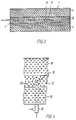
- the trough-shape of the path ensures together with the described orientation of the perforations in the perforated plate serving as air distributor that the main pattern of movement of the material in the apparatus is a double-whirl movement, in which the material flows along the bottom towards the centre line of the path, and in which the flow becomes upwardly directed and at a certain distance from the bottom turns outwards against the sides and downwards along the side walls.
- the perforations lead the gas flow in a direction either directed against or with some component against the outlet for processed material, the material is simultaneously with the quick whirl movement subjected to a slow displacement throught the whole of the trough-shaped path of the apparatus.
- the quick whirl movement which has the effect that the fluidizing gas flows at a comparatively big velocity along the bottom of the trough-shaped path, as well as the fact that the trough-shaped path, contrary to the constructions normally used for related purposes, does not have socalled "dead" areas, where tacky powdery material deposits, has the effect that by use of the apparatus agglomerating processes can be carried through, in which in the initiating phases a substantially bigger moisture content is maintained in the powder than what has been possible by the conventional apparatuses.
- the perforated plate at the bottom of the trough-shaped path may be designed in many ways.
- it comprises a lower part which is a substantially horizontally perforated plate extending centrally throughout the length of the apparatus, and two oblique perforated plates extending on either side of the horizontal plate and connecting the latter with the two non-perforated side walls.
- the perforated plate is constituted by a plate with a curved cross-section profile connecting the two non-perforated side walls.
- the perforated plate may be only a horizontal plate extendng between the two non-perforated side walls.
- the nozzle/nozzles which is/are used for spraying liquid on to the powdery material are positioned centrally in the very zone, in which the fluidized material is present during the operation of the apparatus, and is/are upwardly directed.
- the nozzles to an extensive degree are kept clean from the upwards flow of powder and gas, partly that the nozzles contribute to the desired whirl movement, in particular in case of two-fluid nozzles, such being preferred, when the atomization pressure air emanating from the nozzles enhances the upward flow around the nozzles.
- the nozzles are intended, when the starting material is a powder, to supply an auxiliary liquid enhancing the agglomeration and perhaps enhancing the attainment of further desired properties of the product, for instance by coating.
- the starting material is a solution or a suspension
- the nozzles are used for atomization thereof on particles already formed in the fluidizing bed.
- the invention also relates to a process for agglomeration of a powdery material by use of the apparatus in question, said process being characteristic in that by controlling one or more parameters chosen among: moisture content of the starting material and the amount thereof, amount of atomised liquid, sprayed on the fluidized powder, amount of fludization and drying gas and temperature and moisture thereof, a greater moisture content is maintained in the fluidized powdery material than what would have been the maximally possible moisture content by conventional fluidization with only vertically directed fluidization gas of the powdery material in question.
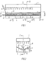
- FIGs. 1-3 a sectional view of an embodiment of an apparatus according to the invention is shown with a housing 1, in which a perforated air distributing plate 2 is provided, said plate in the embodiment shown being constituted by a horizontal plane section 3 and two oblique plane sections 4.
- the perforations are in the embodiment shown so-called gill slits designed for instance as described in EP-A-474949.
- the air distributing plate 2 may be designed as a plate evenly curved around its longitudinal axis, or it may, less preferred, be plane.
- a plenum chamber is provided below this plate, said chamber being divided in sections 5, 6, 7 by partition walls, to which through the ducts 8, 9, 10 fluidizing gas is supplied, for instance hot drying air through the ducts 8 and 9 and unheated cooling air through the duct 10.
- a row of filters 11 are provided in the embodiment shown, through which filters the leaving gas flow passes in such a way that the fine particles entrained therewith are separated and fall back on the central part or the front part of the perforated plate.
- the leaving gas with entrained particles is let out from the housing 1 and a removal of particles may take place in a separate plant (not shown) with possible subsequent back flow of the particles to the fluidized bed.
- a tubular construction 12 extends immediately above the centre line in section 3 for supply of moisturing liquid and atomization pressure gas or vapour.
- This tubular construction carries a number of upwardly directed two-fluid nozzles 13.
- these nozzles may be introduced from the bottom through the air distributing plate 2 and may for instance discharge in level with the upper surface of the horizontal section 3 or be taken somewhat above it.
- Such an embodiment is outlined in Fig. 4, which will be explained in detail in the following.
- the apparatus inlet means 14 are provided for the introduction of the powdery material which is to be agglomerated to a zone positioned immediately above the air distributing plate 2, whereas in the opposite end of the apparatus outlet means 15 for the agglomerated product are provided.
- the inlet means 14 may be omitted.
- the powdery material to be processed is continuously supplied through 14, and fluidization gas is as mentioned supplied through the ducts 8, 9, and 10.
- the openings in the central, horizontal section are directed in such a way that the gas exits therefrom parallel to the longitudinal direction of the air distributing plate and in a direction towards the outlet means 15 for agglomerate.
- the gas which leaves through the openings in the two oblique sections 4 is, however, directed perpendicularly thereto and is in respect of each section 4 directed towards the centre line of the air distributing plate.
- the gas from the two sections 4 will thus substantially impart a movement pattern to the powder introduced like the one shown in Fig. 2, whereas the gas departing through the openings in the horizontal section 2 ensures the conveyance of the material longitudinally through the apparatus.
- This combination is considered particularly advantageous as big agglomerates and lumps, if any, will fall down towards section 3 and will there be subjected to a quick conveyance towards the outlet means 15 in such a way that they quickly leave the apparatus without participating in any further formation of agglomerate.
- the orientation of the openings of the plate may be identical within each half of the plate, the gas being substantially directed towards the centre line of the plate, but with some component towards the outlets.
- the powdery material may either be introduced with big humidity, or operation may be carried out with such a low drying capacity of the fluidization air that a big powder moisture is maintained/attained in the agglomeration phase, and only a supply of a fairly small amount of liquid is required for re-moisturing the material.
- the sections 16 correspond in principle to the sections 4 of the embodiment shown in Figs. 1-3, whereas the section 17 corresponds to section 3 and is thus a horizontal plate.
- the orientation of the openings of the sections 16 and 17 corresponds to what is described in connection with Figs. 1-3.
- a nozzle Up through the section 17 a nozzle extends, which through a tubular construction 19 below the perforated plate supplies moisturing liquid and pressure gas or vapour to the nozzle 18.
- a ring of openings 20 is provided, which supplies gas from the underlying plenum chamber in a direction away from the nozzle.
- vertical holes may further be provided, through which part of the fluidizing air may pass, for instance with a view to increasing the centrally upwards flow in the fluidizing powdery layer.
- the apparatus according to the invention is, as will be seen, particularly suited for carrying out the process described, in which a high moisture percentage in the powdery material is maintained during agglomeration, and hereby it is made posible to attain product properties which in respect of the size of agglomerates and distribution of the size of agglomerates are superior over the prior art, as big agglomerates are attained with such a narrow distribution of grain-size that a subsequent classification is made superfluous.
- the product is attained without the deterioration of quality which may be caused by heavy re-humidification, and that the agglomerates may be obtained with a desired physical strength which allows handling and transport without decomposition, the binding together of the individual particles being at the same time not so strong that their disintegration during reconstitution in the liquid phase is delayed or hindered.
- the good fluidization properties of the apparatus and the movement of pattern for the material therein which is characteristic in two partially united, parallel helical paths extending in the longitudinal direction of the apparatus, ensure a good mixing of the material, the movement through the apparatus, seen in the longitudinal direction, being simultaneously essentially a plug flow without essential back flow, in such a way that the good mixing properties of the apparatus are not attained at the expense of the advantages in respect of a homogenous treatment caused by the plug flow.
- the liquid atomized through the nozzles 13 may be water, where this is sufficient for imparting a sufficient mutual adhesion to the powdery particles.
- the liquid fluidized through said nozzles may also be a solution, a suspension or an emulsion, at the drying of which compounds remain, which further the formation of agglomerates or impart the necessary strength thereto or which form a coating on the particles present in the apparatus for improving their properties, such as is known within many industries, including the pharmaceutical industry and the detergent industry.
- the coating may either be carried out with the same compound, of which the particles or part of these are constituted, or it may be formed by means of an auxiliary compound of another type, for instance with a film-forming polymer.
- such a coating operation may take place in the lower part of the apparatus, with respect to the flop direction of the material.
- the ratio between the material, which is introduced into the apparatus as a powder, and the material which is introduced as a liquid may vary within so wide limits that the total amount of solid may be introduced with the liquid through the nozzles, the apparatus thus functioning as an actual drying apparatus and the good fluidization properties and the homogenous particle treatment being also in this case of essential importance. If the whole amount of solid of the end product is supplied with the liquid phase sprayed in through the nozzles, it is apparently not necessary to provide the apparatus with the above described and in the claims mentioned inlet means 14 for powdery material.
- the apparatus according to the invention may be designed in such a way that it comprises a number of parallel trough-shaped paths, each comprising a perforated plate and being mutually separated by vertical or steeply slanting side walls, said paths being connected in series for passage of powder or agglomerate therethrough.
- the invention may be carried out in conncection with processes similar to the known "Multi Stage Drying", i.e. a process, in which a fluidized bed built together with an atomization plant is used, the product therefrom being directly received in the fluidized bed.
- Multi Stage Drying i.e. a process, in which a fluidized bed built together with an atomization plant is used, the product therefrom being directly received in the fluidized bed.
- the apparatus according to the invention is characeristic in comprising an atomization drying chamber with a bottom section, the lower part of which constitutes said inlets for powdery material to the zone above the air distributing plate.
- the fluidized bed is connected directly to an atomization chamber that the apparatus comprises at least two parallelly extending trough-shaped paths, said paths each having an end extending under said bottom section of the atomization drying chamber for direct receipt of powdery material therefrom.
- the fluidization gas, which leaves this fluidized bed, may in this case be recovered together with the used atomization drying gas from the atomization drying chamber, but it may, in order to avoid introducing the relatively cool fluidization gas in the chamber, be advantageous to use a separate outlet for the fluidization gas.
- the perforated plate was substantially horiziontal but had upwardly bent edges united with the nearly vertical side walls of the trough-shaped path.
- the width of the perforated plate was 32 cm, and the total length of the trough-shaped path comprising six plate units was 15 m, divided into a first section of 2.5 m, a second section of 5 m, and a third section of 7.5 m.
- the perforations of the plate were so-called gill slits, which were all directed towards the centre line of the perforated plate with a small component in the longitudinal direction of the path towards the outlet for finished agglomerate.
- a fatty milk substitute consisting of a mixture of a number of different ingredients was used as starting material.
- the amount of free fat in the starting material was 1.71%.
- Fluidizing air at a temperature of 75°C was led to the apparatus, which resulted in a powder temperature in the range of 30°C to 35°C through the apparatus.
- the milk substitute was added in an amount of 3500 kg/hour, and spraying of water through the nozzles only corresponded to 8% of the amount of powder introduced.
- the content of the agglomerated product of free fat was 1.45%. This decrease of the amount of free fat must be attributed to the fact that the agglomerated final product had a smaller surface than the starting material, but although this fact is taken into account, the analyses of free fat can be taken as a proof that the increase of the amount of free fat on the individual particles, which occurs by conventional processes with a more intensive rehumification, has been substantially avoided by use of the apparatus according to the invention.
- Example 2 The same apparatus as the one described in Example 1 was used, and the staring material was also here a fatty milk substitute, and the agglomeration liquid was water.
- the inlet temperature of the fluidizing gas was 60°C, and the powder temperture through the plant was in the range of 30°C to 35°C.
- the particle size distribution of the end material was determined after the passage of the material through the first section, after its passage through the second section and in the end product.
Landscapes
- Chemical & Material Sciences (AREA)
- Organic Chemistry (AREA)
- Chemical Kinetics & Catalysis (AREA)
- Engineering & Computer Science (AREA)
- Combustion & Propulsion (AREA)
- Drying Of Solid Materials (AREA)
- Graft Or Block Polymers (AREA)
- Nonmetallic Welding Materials (AREA)
- Physical Or Chemical Processes And Apparatus (AREA)
- Glass Compositions (AREA)
- Formation And Processing Of Food Products (AREA)
Applications Claiming Priority (6)
| Application Number | Priority Date | Filing Date | Title |
|---|---|---|---|
| WOPCT/DK93/00372 | 1993-11-15 | ||
| PCT/DK1993/000372 WO1995013867A1 (en) | 1993-11-15 | 1993-11-15 | Fluid bed for producing and/or processing a particulate material |
| DK62919 | 1994-06-03 | ||
| DK062994A DK62994A (da) | 1993-11-15 | 1994-06-03 | Apparat og fremgangsmåde til fremstilling af et agglomereret materiale |
| DK629/19 | 1994-06-03 | ||
| PCT/DK1994/000429 WO1995013865A1 (en) | 1993-11-15 | 1994-11-15 | An apparatus and a process for the preparation of an agglomerated material |
Publications (2)
| Publication Number | Publication Date |
|---|---|
| EP0729384A1 EP0729384A1 (en) | 1996-09-04 |
| EP0729384B1 true EP0729384B1 (en) | 1998-01-14 |
Family
ID=26064347
Family Applications (1)
| Application Number | Title | Priority Date | Filing Date |
|---|---|---|---|
| EP95901351A Expired - Lifetime EP0729384B1 (en) | 1993-11-15 | 1994-11-15 | An apparatus and a process for the preparation of an agglomerated material |
Country Status (9)
| Country | Link |
|---|---|
| US (1) | US5695701A (da) |
| EP (1) | EP0729384B1 (da) |
| JP (1) | JP2000513991A (da) |
| AT (1) | ATE162111T1 (da) |
| AU (1) | AU694464B2 (da) |
| DE (1) | DE69407996T2 (da) |
| DK (2) | DK62994A (da) |
| NZ (1) | NZ276374A (da) |
| WO (1) | WO1995013865A1 (da) |
Cited By (1)
| Publication number | Priority date | Publication date | Assignee | Title |
|---|---|---|---|---|
| EP0900589A1 (en) | 1997-09-04 | 1999-03-10 | Toyo Engineering Corporation | Method for granulation and granulator |
Families Citing this family (21)
| Publication number | Priority date | Publication date | Assignee | Title |
|---|---|---|---|---|
| US6383810B2 (en) * | 1997-02-14 | 2002-05-07 | Invitrogen Corporation | Dry powder cells and cell culture reagents and methods of production thereof |
| DE19750424A1 (de) * | 1997-11-14 | 1999-05-20 | Henkel Kgaa | Verbessertes Verfahren zum Herstellen von Tensidgranulaten mit einem hohen Schüttgewicht |
| US6685886B2 (en) | 1998-12-17 | 2004-02-03 | Genencor International, Inc. | Agitation system for a fluid bed processing system and a method thereof |
| DE19904147C2 (de) * | 1999-02-03 | 2001-05-10 | Herbert Huettlin | Vorrichtung zum Behandeln von partikelförmigem Gut |
| US6730349B2 (en) | 1999-04-19 | 2004-05-04 | Scimed Life Systems, Inc. | Mechanical and acoustical suspension coating of medical implants |
| HK1049621A1 (zh) | 1999-06-09 | 2003-05-23 | 罗伯特‧E‧希弗斯 | 超临界流体辅助的喷雾和鼓泡乾燥 |
| DK1064990T3 (da) | 1999-06-29 | 2004-05-24 | Aeromatic Fielder Ag | Fremgangsmåde til granulering af et partikelformet materiale |
| DK1126017T3 (da) * | 2000-02-18 | 2006-02-06 | Glatt Ingtech Gmbh | Fremgangsmåde til fremstilling af höjeffektive vaskemidler og komponenter i höjeffektive vaskemidler |
| DE10054557C2 (de) * | 2000-10-31 | 2003-11-13 | Herbert Huettlin | Vorrichtung zum Behandeln von partikelförmigem Gut |
| ATE347441T1 (de) * | 2001-03-21 | 2006-12-15 | Urea Casale Sa | Wirbelschichtgranulation |
| JP2002292266A (ja) * | 2001-03-30 | 2002-10-08 | Okawara Mfg Co Ltd | 被処理物の流動を促進させた流動層造粒乾燥装置 |
| DE10130334A1 (de) * | 2001-06-26 | 2003-01-02 | Glatt Ingtech Gmbh | Verfahren zum Coating von körnigen und pulverförmigen Materialien |
| DE10217758B4 (de) * | 2002-04-20 | 2005-06-16 | Krauss-Maffei Kunststofftechnik Gmbh | Rückstromsperre für Spritzgießmaschine |
| JO2790B1 (en) * | 2002-11-26 | 2014-03-15 | أومنيا فيرتيليزر ليمتد | Apparatuses for the production of nitrate granules |
| EP1491252A1 (en) * | 2003-06-26 | 2004-12-29 | Urea Casale S.A. | Fluid bed granulation process and apparatus |
| CN101432063B (zh) * | 2006-05-02 | 2013-02-13 | 尼罗有限公司 | 凝聚装置及用于制造凝聚颗粒的方法 |
| CN102230717B (zh) * | 2011-08-01 | 2014-10-29 | 长沙通发高新技术开发有限公司 | 沸腾旋流流化床的床体结构 |
| CN103406270A (zh) * | 2013-08-24 | 2013-11-27 | 中能东讯新能源科技(大连)有限公司 | 一种干法选择性固体物料二级分离装置 |
| EP3768417A1 (en) * | 2018-03-23 | 2021-01-27 | thyssenkrupp Fertilizer Technology GmbH | Divided perforated plate for fluid bed granulator or cooler |
| MX2021009571A (es) * | 2019-02-11 | 2021-09-08 | Gen Kinematics Corp | Aparato vibratorio con placa soporte de distribuidor segmentada. |
| DE102019216894A1 (de) * | 2019-10-31 | 2021-05-06 | Thyssenkrupp Ag | Fließbettgranulator |
Family Cites Families (13)
| Publication number | Priority date | Publication date | Assignee | Title |
|---|---|---|---|---|
| US4033555A (en) * | 1971-01-11 | 1977-07-05 | The Motch & Merryweather Machinery Company | Fluidized bed for treating granular material |
| DE2421278A1 (de) * | 1973-05-10 | 1974-11-28 | Anhydro As | Apparat zur behandlung fluidisierter materialien |
| GB1504282A (en) * | 1974-02-16 | 1978-03-15 | Farrel Bridge Ltd | Methods of and apparatus for treating particulate material with a gas |
| GB1581761A (en) * | 1977-06-09 | 1980-12-17 | Azote Sa Cie Neerlandaise | Urea granulation |
| CH635862A5 (de) * | 1977-10-15 | 1983-04-29 | Ciba Geigy Ag | Verfahren zur granulierung von pigmenten. |
| CH652940A5 (de) * | 1982-01-09 | 1985-12-13 | Sandoz Ag | Verfahren zur herstellung nicht staubender granulate und vorrichtung hierfuer. |
| US4507335A (en) * | 1984-02-13 | 1985-03-26 | Procor Limited | Method and apparatus for pelletizing sulphur |
| US4698190A (en) * | 1985-09-02 | 1987-10-06 | Kabushiki Kaisha Okawaraseisakusho | Method and apparatus of controlling granulation of moisture-absorbing powder material |
| JPS6274443A (ja) * | 1985-09-27 | 1987-04-06 | Toyo Eng Corp | 粒子の加工方法 |
| SU1586765A1 (ru) * | 1988-05-03 | 1990-08-23 | Тамбовский институт химического машиностроения | Установка дл гранулировани мелкодисперсных материалов |
| DE3908022C1 (da) * | 1988-09-23 | 1990-03-29 | Degussa Ag, 6000 Frankfurt, De | |
| DE4000572C1 (da) * | 1990-01-10 | 1991-02-21 | Herbert 7853 Steinen De Huettlin | |
| US5211985A (en) * | 1991-10-09 | 1993-05-18 | Ici Canada, Inc. | Multi-stage process for continuous coating of fertilizer particles |
-
1994
- 1994-06-03 DK DK062994A patent/DK62994A/da unknown
- 1994-11-15 EP EP95901351A patent/EP0729384B1/en not_active Expired - Lifetime
- 1994-11-15 US US08/564,149 patent/US5695701A/en not_active Expired - Fee Related
- 1994-11-15 DK DK95901351T patent/DK0729384T3/da active
- 1994-11-15 NZ NZ276374A patent/NZ276374A/en unknown
- 1994-11-15 AT AT95901351T patent/ATE162111T1/de not_active IP Right Cessation
- 1994-11-15 AU AU10630/95A patent/AU694464B2/en not_active Ceased
- 1994-11-15 JP JP07514162A patent/JP2000513991A/ja active Pending
- 1994-11-15 DE DE69407996T patent/DE69407996T2/de not_active Expired - Fee Related
- 1994-11-15 WO PCT/DK1994/000429 patent/WO1995013865A1/en not_active Ceased
Cited By (1)
| Publication number | Priority date | Publication date | Assignee | Title |
|---|---|---|---|---|
| EP0900589A1 (en) | 1997-09-04 | 1999-03-10 | Toyo Engineering Corporation | Method for granulation and granulator |
Also Published As
| Publication number | Publication date |
|---|---|
| DK62994A (da) | 1995-05-16 |
| DE69407996D1 (de) | 1998-02-19 |
| ATE162111T1 (de) | 1998-01-15 |
| DE69407996T2 (de) | 1998-08-13 |
| AU694464B2 (en) | 1998-07-23 |
| NZ276374A (en) | 1997-01-29 |
| US5695701A (en) | 1997-12-09 |
| JP2000513991A (ja) | 2000-10-24 |
| WO1995013865A1 (en) | 1995-05-26 |
| EP0729384A1 (en) | 1996-09-04 |
| AU1063095A (en) | 1995-06-06 |
| DK0729384T3 (da) | 1998-09-14 |
Similar Documents
| Publication | Publication Date | Title |
|---|---|---|
| US5695701A (en) | Apparatus and a process for the preparation of an agglomerated material | |
| EP0961646B1 (en) | Spray drying method and apparatus and cleaning method for such an apparatus | |
| EP0641236B1 (en) | A method for coated particles in a spray-drying plant | |
| EP0378498A1 (en) | Process and spray drying apparatus for producing stable particle agglomerates | |
| US4490403A (en) | Process for producing an agglomerated powdery milk product | |
| US5632100A (en) | Process and a spray drying apparatus for producing an agglomerated powder | |
| JP2003501252A (ja) | 噴霧乾燥プラント、およびその使用方法 | |
| US4871398A (en) | Method for pregelatinized, spray-dried starch agglomerates | |
| JP2006525861A (ja) | 噴流層装置の固体流に液体を付与するための方法及び装置 | |
| US7691438B2 (en) | Enzyme granulate production method and resulting enzyme granulates | |
| EP1227732B1 (en) | A process for producing a spray dried, agglomerated powder of baby food, whole-milk or skim-milk, and such powder | |
| US5130156A (en) | Method for agglomerating food powders | |
| US20060035022A1 (en) | Process to coat granular and powdered materials | |
| DE10326231B4 (de) | Verfahren zur Herstellung von Enzym-Granulaten | |
| US5069118A (en) | Mechanism and method for agglomerating food powders | |
| JPH0613091B2 (ja) | 噴霧乾燥流動造粒方法 | |
| US7709036B2 (en) | Method for granulating malt extracts | |
| AU545120B2 (en) | Improvements relating to manufacturing of caseinates | |
| NZ258862A (en) | Spray drying with pneumatic refeeding of fine particles providing upward outward annular drying near conical chamber wall | |
| DE102004004202A1 (de) | Herstellungsverfahren für Enzym-Granulate und erhältliche Enzym-Granulate |
Legal Events
| Date | Code | Title | Description |
|---|---|---|---|
| PUAI | Public reference made under article 153(3) epc to a published international application that has entered the european phase |
Free format text: ORIGINAL CODE: 0009012 |
|
| 17P | Request for examination filed |
Effective date: 19960419 |
|
| AK | Designated contracting states |
Kind code of ref document: A1 Designated state(s): AT BE CH DE DK ES FR GB IE IT LI NL SE |
|
| 17Q | First examination report despatched |
Effective date: 19960920 |
|
| GRAG | Despatch of communication of intention to grant |
Free format text: ORIGINAL CODE: EPIDOS AGRA |
|
| GRAH | Despatch of communication of intention to grant a patent |
Free format text: ORIGINAL CODE: EPIDOS IGRA |
|
| GRAH | Despatch of communication of intention to grant a patent |
Free format text: ORIGINAL CODE: EPIDOS IGRA |
|
| GRAA | (expected) grant |
Free format text: ORIGINAL CODE: 0009210 |
|
| AK | Designated contracting states |
Kind code of ref document: B1 Designated state(s): AT BE CH DE DK ES FR GB IE IT LI NL SE |
|
| PG25 | Lapsed in a contracting state [announced via postgrant information from national office to epo] |
Ref country code: LI Free format text: LAPSE BECAUSE OF FAILURE TO SUBMIT A TRANSLATION OF THE DESCRIPTION OR TO PAY THE FEE WITHIN THE PRESCRIBED TIME-LIMIT Effective date: 19980114 Ref country code: IT Free format text: LAPSE BECAUSE OF FAILURE TO SUBMIT A TRANSLATION OF THE DESCRIPTION OR TO PAY THE FEE WITHIN THE PRE;WARNING: LAPSES OF ITALIAN PATENTS WITH EFFECTIVE DATE BEFORE 2007 MAY HAVE OCCURRED AT ANY TIME BEFORE 2007. THE CORRECT EFFECTIVE DATE MAY BE DIFFERENT FROM THE ONE RECORDED.SCRIBED TIME-LIMIT Effective date: 19980114 Ref country code: ES Free format text: THE PATENT HAS BEEN ANNULLED BY A DECISION OF A NATIONAL AUTHORITY Effective date: 19980114 Ref country code: CH Free format text: LAPSE BECAUSE OF FAILURE TO SUBMIT A TRANSLATION OF THE DESCRIPTION OR TO PAY THE FEE WITHIN THE PRESCRIBED TIME-LIMIT Effective date: 19980114 Ref country code: BE Free format text: LAPSE BECAUSE OF FAILURE TO SUBMIT A TRANSLATION OF THE DESCRIPTION OR TO PAY THE FEE WITHIN THE PRESCRIBED TIME-LIMIT Effective date: 19980114 Ref country code: AT Free format text: LAPSE BECAUSE OF FAILURE TO SUBMIT A TRANSLATION OF THE DESCRIPTION OR TO PAY THE FEE WITHIN THE PRESCRIBED TIME-LIMIT Effective date: 19980114 |
|
| REF | Corresponds to: |
Ref document number: 162111 Country of ref document: AT Date of ref document: 19980115 Kind code of ref document: T |
|
| REG | Reference to a national code |
Ref country code: CH Ref legal event code: EP |
|
| REF | Corresponds to: |
Ref document number: 69407996 Country of ref document: DE Date of ref document: 19980219 |
|
| ET | Fr: translation filed | ||
| PG25 | Lapsed in a contracting state [announced via postgrant information from national office to epo] |
Ref country code: SE Free format text: LAPSE BECAUSE OF FAILURE TO SUBMIT A TRANSLATION OF THE DESCRIPTION OR TO PAY THE FEE WITHIN THE PRESCRIBED TIME-LIMIT Effective date: 19980414 |
|
| REG | Reference to a national code |
Ref country code: IE Ref legal event code: FG4D Free format text: 78426 |
|
| REG | Reference to a national code |
Ref country code: CH Ref legal event code: PL |
|
| REG | Reference to a national code |
Ref country code: DK Ref legal event code: T3 |
|
| PG25 | Lapsed in a contracting state [announced via postgrant information from national office to epo] |
Ref country code: IE Free format text: LAPSE BECAUSE OF NON-PAYMENT OF DUE FEES Effective date: 19981115 |
|
| PLBE | No opposition filed within time limit |
Free format text: ORIGINAL CODE: 0009261 |
|
| STAA | Information on the status of an ep patent application or granted ep patent |
Free format text: STATUS: NO OPPOSITION FILED WITHIN TIME LIMIT |
|
| 26N | No opposition filed | ||
| REG | Reference to a national code |
Ref country code: FR Ref legal event code: CL |
|
| PGFP | Annual fee paid to national office [announced via postgrant information from national office to epo] |
Ref country code: GB Payment date: 20011023 Year of fee payment: 8 |
|
| PGFP | Annual fee paid to national office [announced via postgrant information from national office to epo] |
Ref country code: DK Payment date: 20011112 Year of fee payment: 8 |
|
| PGFP | Annual fee paid to national office [announced via postgrant information from national office to epo] |
Ref country code: FR Payment date: 20011128 Year of fee payment: 8 Ref country code: DE Payment date: 20011128 Year of fee payment: 8 |
|
| PGFP | Annual fee paid to national office [announced via postgrant information from national office to epo] |
Ref country code: NL Payment date: 20011130 Year of fee payment: 8 |
|
| REG | Reference to a national code |
Ref country code: GB Ref legal event code: IF02 |
|
| PG25 | Lapsed in a contracting state [announced via postgrant information from national office to epo] |
Ref country code: GB Free format text: LAPSE BECAUSE OF NON-PAYMENT OF DUE FEES Effective date: 20021115 |
|
| PG25 | Lapsed in a contracting state [announced via postgrant information from national office to epo] |
Ref country code: DK Free format text: LAPSE BECAUSE OF NON-PAYMENT OF DUE FEES Effective date: 20021231 |
|
| PG25 | Lapsed in a contracting state [announced via postgrant information from national office to epo] |
Ref country code: NL Free format text: LAPSE BECAUSE OF NON-PAYMENT OF DUE FEES Effective date: 20030601 |
|
| PG25 | Lapsed in a contracting state [announced via postgrant information from national office to epo] |
Ref country code: DE Free format text: LAPSE BECAUSE OF NON-PAYMENT OF DUE FEES Effective date: 20030603 |
|
| GBPC | Gb: european patent ceased through non-payment of renewal fee | ||
| REG | Reference to a national code |
Ref country code: DK Ref legal event code: EBP |
|
| PG25 | Lapsed in a contracting state [announced via postgrant information from national office to epo] |
Ref country code: FR Free format text: LAPSE BECAUSE OF NON-PAYMENT OF DUE FEES Effective date: 20030731 |
|
| NLV4 | Nl: lapsed or anulled due to non-payment of the annual fee |
Effective date: 20030601 |
|
| REG | Reference to a national code |
Ref country code: FR Ref legal event code: ST |