EP0729672B1 - Elektronische schalteranordnung - Google Patents
Elektronische schalteranordnung Download PDFInfo
- Publication number
- EP0729672B1 EP0729672B1 EP95901504A EP95901504A EP0729672B1 EP 0729672 B1 EP0729672 B1 EP 0729672B1 EP 95901504 A EP95901504 A EP 95901504A EP 95901504 A EP95901504 A EP 95901504A EP 0729672 B1 EP0729672 B1 EP 0729672B1
- Authority
- EP
- European Patent Office
- Prior art keywords
- switches
- switch
- terminals
- output
- input
- Prior art date
- Legal status (The legal status is an assumption and is not a legal conclusion. Google has not performed a legal analysis and makes no representation as to the accuracy of the status listed.)
- Expired - Lifetime
Links
- 238000012360 testing method Methods 0.000 description 21
- 235000021183 entrée Nutrition 0.000 description 9
- 238000009434 installation Methods 0.000 description 5
- 238000010586 diagram Methods 0.000 description 3
- 241001080024 Telles Species 0.000 description 2
- 230000005540 biological transmission Effects 0.000 description 2
- 230000015556 catabolic process Effects 0.000 description 2
- 238000005259 measurement Methods 0.000 description 2
- 230000003071 parasitic effect Effects 0.000 description 2
- 229910000980 Aluminium gallium arsenide Inorganic materials 0.000 description 1
- 229910001218 Gallium arsenide Inorganic materials 0.000 description 1
- 235000015842 Hesperis Nutrition 0.000 description 1
- 235000012633 Iberis amara Nutrition 0.000 description 1
- 240000008042 Zea mays Species 0.000 description 1
- 238000006243 chemical reaction Methods 0.000 description 1
- 238000004590 computer program Methods 0.000 description 1
- 230000008520 organization Effects 0.000 description 1
- 230000000135 prohibitive effect Effects 0.000 description 1
- 230000003252 repetitive effect Effects 0.000 description 1
- 238000010998 test method Methods 0.000 description 1
Images


Classifications
-
- H—ELECTRICITY
- H03—ELECTRONIC CIRCUITRY
- H03K—PULSE TECHNIQUE
- H03K17/00—Electronic switching or gating, i.e. not by contact-making and –breaking
- H03K17/002—Switching arrangements with several input- or output terminals
- H03K17/007—Switching arrangements with several input- or output terminals with several outputs only
-
- H—ELECTRICITY
- H03—ELECTRONIC CIRCUITRY
- H03K—PULSE TECHNIQUE
- H03K17/00—Electronic switching or gating, i.e. not by contact-making and –breaking
- H03K17/51—Electronic switching or gating, i.e. not by contact-making and –breaking characterised by the components used
- H03K17/78—Electronic switching or gating, i.e. not by contact-making and –breaking characterised by the components used using opto-electronic devices, i.e. light-emitting and photoelectric devices electrically- or optically-coupled
Definitions
- the present invention relates to a switching assembly electric.
- the invention relates to a device controllable which allows to selectively connect a pair of terminals switching device input to any of n pairs of switching device output terminals.
- harness / bus In the particular case of space installations, this type Interconnection system known as harness / bus must meet the MIL-STD-1553B standard. However, for other types of installation, it is necessary to check that the interconnections meet the same type of standards.
- the different interconnection systems must be tested in different configurations, i.e. when successively each of the components connected by the lines of bypass behaves as a transmitter, when it behaves as a receiver, when an input load is applied to it which simulates a card, that is to say an electronic circuit and possibly when one of receivers or transmitters which will be called later subscriber is in short circuit or open circuit in order to simulate damage on the whole installation in order to test its behavior in a such configuration.
- the switching assembly is constituted by a binary tree structure of switch sets arranged in lines. State of switches on the same line is controlled simultaneously and the order status of each line switch allows electrically connecting external terminals from the switch assembly to a single pair of output terminals or connection input, these pairs of terminals being themselves connected to branch line status circuits, i.e. to cards "subscriber".
- This tree-like arrangement simplifies the control of the switching assembly while allowing connection uniquely the external input terminals to the connection terminals Release. This arrangement also makes it possible to shorten the length of line.
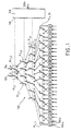
- the switching assembly 100 is essentially constituted by p lines of elementary switches carrying the generic reference K.
- the first line of switches is constituted by two elementary switches K 1,1 and K 1,2 whose inputs carrying the generic reference a are respectively connected to the input terminals 102 and 104 of the switching assembly.
- each switch K i, j has two output terminals respectively referenced b and c.
- the second switch line comprises four elementary switches therefore bearing the references K 2.1 to K 2.4 .
- Each first output terminal b of a switch of line i is connected to input terminal a of a switch of line i + 1 and each output terminal c of a switch of line i is connected to input a from another switch on line i + 1.
- a tree structure of switches is thus obtained, a line i comprising twice as many switches as line i-1. More generally, the line i of elementary switches K i, j comprises 2 i switches. In the example considered, the switching assembly comprises four lines of elementary switches, which means that the fourth line comprises 2 4 elementary switches referenced K 4.1 to K 4.16 .
- the outputs b and c of the elementary switches K of the last line are connected respectively to the external positive output terminals 106a of the switching assembly and to the negative terminals 106b of the switching assembly.
- the switch comprises a control assembly 108 comprising as many outputs command 110 that there are elementary switch lines, that is to say four in the example considered.
- Each exit 110 from control device 108 allows simultaneous connection of the inputs has elementary switches of the same line at terminals b of output or simultaneously to the output terminals c.
- An instruction complete switch 100 command therefore consists of four binary information indicating whether the elementary switches K of a line i must be in a position that connects its input a to the terminal c or in a position which connects its input a to terminal b.
- the bipolar elementary switches K can be of any kind.
- the means of controlling the "contact mobile "switches, which are only symbolized in FIG. 1 by dotted lines, can be of any kind.
- the tree structure of the switching assembly 100 has many advantages. On the one hand, the order of the switch is simplified since it suffices to provide p information binaries to connect the external terminals connected to the generator signals or to the measuring device at one of the 2P pairs of terminals linked to "subscriber" cards. On the other hand, each defined electrical path between the pair of input terminals and any of the output terminals has the same number of intermediate contacts, which ensures same electrical conduction qualities whatever the route, the path lengths are also all substantially equal. Of more, for each command of the elementary switches, these only define two electrical paths that actually go input terminals to a pair of output terminals and no partial path seen from the input terminals, which avoids parasitic phenomena which could be induced by partial paths connected to the input terminals.
- Bus 10 to be tested which is connected to test device 12.
- Bus 10 consists of a line main 14 to which n derivative lines are connected 16.
- Each branch line 16 is connected to main line 14 by a coupler electric 18.
- the electrical test device basically consists of a control assembly 20 for applying and controlling the battery of tests to be subjected to bus 10, an electrical measuring device 22 such as an oscilloscope or a recorder, a signal generator electric controllable 24, a first and a second switch electrical, respectively referenced 26 and 28, and m state circuits of derived lines with the generic reference 30 which will be subsequently called by simplification "subscriber" cards.
- Switches 26 and 28 have the architecture described in connection with figure 1.
- the control assembly 20 is essentially constituted by a computer machine 32 associated with a program memory 34 which allows you to control the progress of different configurations tests to be applied to bus 10.
- the computing device 32 is preference associated with means for displaying and printing results 36.
- the computer control device 32 is also coupled to a converter 38 which converts the instructions issued by the computing device 32 into executable control signals allowing to control the state of the various components of the device tests 12, the computer control device 32 is also connected at the control input 24a of the electrical signal generator 24 in order to define the form of the electrical signal that will be applied for the test phase considered.
- each line derivative 16 of bus 10 is connected to the input and / or output of a card "subscriber" 30.
- Each "subscriber” card 30 is connected to an output 40 of the first switch 26 and to an input 42 of the second switch 28.
- the switch 26 has its input 44 which is connected to the output of the electrical signal generator 24 while the output 46 of the second switch 28 is connected to the input of the measuring device electric 22.
- the converter 38 has a first output 48 which is connected to the control input 28a of the switch 28 and a second control output 50 which is connected to the input of control 26a of the first switch 26.
- the switch 26 makes it possible to connect its input 44 to one of the outputs 40 of this switch and therefore to one of the m cards "subscriber" 30.
- the switch 28 makes it possible to connect one of its inputs 42, that is to say one of the "subscriber” cards 30 to its output 46, that is to say the measuring device 22.
- the device for conversion 38 has a third command output 52 which is connected to the control input 30a of each of the "subscriber" cards 30.
- the converter by its output 52 can apply to each "subscriber” card a control signal which allows, as will be explained more in details later, to define the state of each of the derived lines 16 during a test phase.
- control signal applied to the inputs 30a of the "subscriber” cards 30 This can connect the branch line associated with it to the electrical signal generator 24 or else to the measuring device 22 or to neither of these two devices.
- the control signal can put the "subscriber” card in a state corresponding to a short circuit of the branch line 16 corresponding or represent the normal operating load applied to it.
- a derived line is transmitting
- a derived line is receiver
- the other branch lines are either shorted out for simulate a fault, either in open circuit or affected by their load normal.
- the implementation of the test stage therefore consists in defining by program 34 the number of the transmitting branch line 16, the number of the receiving branch line 16 and the state of each of the others derived lines. It is also necessary to define the information giving the characteristics of the signal to be emitted by the branch line transmitter and possibly the nature of the measurements to be carried out.
- This various information is transmitted to the converter 38 who will order on the one hand the various "subscriber” cards 30 in depending on the state of the derived line associated with them. More specifically, one of the "subscriber” cards will be ordered to connect the line derived from generator 24 of electrical signals and another card to connect the "subscriber” card to the measuring device 22. The other cards “subscriber” are ordered to take one of the other possible states. Simultaneously the converter 38 controls the switches 26 and 28 in such a way that the issuing "subscriber” card is effectively connected to generator 24 and that the receiving "subscriber” card is actually connected to the measuring device 22. In addition, the generator electrical signals 24 is controlled to apply the signal form electrical system desired for the test.
- the measuring device 22 develops the measurement of electrical characteristics provided for in the test, these measures being transmitted to the computer device 32 which allows their processing and possibly their display on the display device 36, or on a paper support or their storage on a support computer science.
- FIG 3 there is shown a preferred embodiment the first switch 26 for connecting the "subscriber" cards to electrical signal generators 24 as well as a preferred mode of creation of a "subscriber” card 30.
- This switch has the structure already described ..
- the switching 26 is essentially constituted by p lines of elementary switches carrying the generic reference K.
- the first line of switches is constituted by two elementary switches K 1,1 and K 1,2 whose inputs carrying the generic reference a are respectively connected to the output terminals 24b and 24c of the generator 24.
- the outputs b and c of the elementary switches K of the last line are connected respectively to the external positive output terminals 40a of the switching assembly and to the negative terminals 40b of the switching assembly .
- the switch comprises a control assembly 60 comprising as many outputs of controls 62 that there are elementary switch lines, that is to say four in the example considered.
- Each output 62 of the device 60 allows simultaneous connection of the inputs to elementary switches of the same line at the output terminals b or simultaneously at the output terminals c.
- a full instruction of command of switch 26 therefore consists of four pieces of information binaries indicating whether the switches of a line i should be in a position which connects its input a to the terminal c or in a position which connect its input a to terminal b.
- a mode preferred to produce a "subscriber” card 30 This includes a first input / output pair constituted by the positive terminal 70a and the negative terminal 70b. Terminals 70a and 70b, as already explained, are connected to a branch line 16 of the bus 10 to be tested.
- the map "subscriber” has a second pair of external connection terminals 72a, 72b which is intended to be connected to a pair of external terminals of output 40a, 40b of the switch 26.
- the card 30 also includes a third pair of external terminals 74a, 74b intended to be connected to the external input terminals of switch 28, as will explain it later.
- Bipolar switches 76 and 78 allow the connection between terminals 70a, 70b and terminals 72a, 72b and 74a, 74b respectively or on the contrary to interrupt this connection.
- Terminals 70a, 70b can also be connected to a load 80 simulating the normal load which is applied to a branch line in non-transmitting and non-transmitting operation receiver, this link being able to be realized by the switch 82, or to simulate a short circuit which can be produced by the conductive line 84 via switch 86.
- the "subscriber" card includes also a control circuit 88 which makes it possible to control individually the open or closed position of the switches 76, 78, 82 and 86 depending on the state in which the derived line associated with the card "subscriber" must be placed. In other words, the control circuit 88 receives on the command input of the card 30a a series of instructions which order the closing of one of the four switches, the other three remaining in the open position.
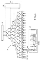
- FIG. 4 shows a preferred embodiment of the switch 28. This one has exactly the same architecture as the switch 26. We simply understand that what constituted the external output terminals now constitute the external terminals input 42a and 42b of the switch to connect each "subscriber" card 30 to the electrical measuring device 22. More precisely, as the shown in FIG. 4, these are the terminals 74a and 74b of the "subscriber" card 30 which are connected to the external input terminals 42a and 42b of the switch 28. This is controlled by line by the control circuit 90 which receives instructions on entry 28a.
Landscapes
- Monitoring And Testing Of Exchanges (AREA)
- Electronic Switches (AREA)
- Keying Circuit Devices (AREA)
- Tests Of Electronic Circuits (AREA)
Claims (2)
- Schaltanordnung, umfassend:zwei äußere Anschlüsse (102, 104), welche den Eingang der Schaltanordnung bilden;p Schalterlinien, wobei die Linie i 2i Schalter umfasst, jeder Schalter (K) einen Eingangsanschluss (a), einen ersten (b) und einen zweiten (c) Ausgangsanschluss und steuerbare elektrische Verbindungsmittel umfasst, um selektiv den Eingangsanschluss mit dem ersten oder dem zweiten Ausgangsanschluss zu verbinden, wobei jeder der ersten oder zweiten Ausgangsanschlüsse der Schalter der Linie i mit dem Eingangsanschluss (a) eines Schalters der Linie i+1 verbunden ist, und die zwei äußeren Anschlüsse jeweils mit den Eingangsanschlüssen der zwei Schalter (K1,1, K1,2) der ersten Linie verbunden sind; undSteuermittel (108) zum Steuern der steuerbaren elektrischen Verbindungsmittel der Schalter, wobei die Anordnung dadurch gekennzeichnet ist, dassdie Steuermittel p Ausgänge (110) umfassen, wobei jeder Ausgang mit allen steuerbaren elektrischen Verbindungsmitteln einer gleichen Schalterlinie verbunden ist, und Mittel um an jedem Ausgang der Steuermittel ein binäres Steuersignal auf solche Art anzulegen, dass entsprechend dem Binärzustand des an einen Ausgang der Steuermittel angelegten Signals der Eingangsanschluss jedes Schalters der betrachteten Linie mit dem ersten Ausgangsanschluss (b) des Schalters verbunden ist, oder dass der Eingangsanschluss jedes Schalters mit dem zweiten Ausgangsanschluss (c) des Schalters verbunden ist;jeder der 2P ersten Ausgangsanschlüsse und jeder der 2P zweiten Ausgangsanschlüsse mit einem der Eingangsanschlüsse oder Ausgangsverbindungsanschlüsse verbunden ist, und die ersten und zweiten Ausgangsanschlüsse der Schalter der i-ten Linien mit den Eingangsanschlüssen der Schalter der (i+1)-ten Linien auf solche Weise verbunden sind, dass für jede Kombination der binären Steuerzustände der Steuermittel der Schalterlinien, die zwei äußeren Anschlüsse (102, 104) der Schaltanordnung mit einem beliebigen, eindeutigen Paar von Ausgangsverbindungsanschlüssen (106a, 106b) verbunden werden können.
- Schaltanordnung nach Anspruch 1, dadurch gekennzeichnet, dass die Schalter (K) bipolar sind und durch Optokoppler gesteuert werden.
Applications Claiming Priority (3)
| Application Number | Priority Date | Filing Date | Title |
|---|---|---|---|
| FR9313776 | 1993-11-18 | ||
| FR9313776A FR2712753B1 (fr) | 1993-11-18 | 1993-11-18 | Ensemble de commutation électrique. |
| PCT/FR1994/001350 WO1995014333A1 (fr) | 1993-11-18 | 1994-11-18 | Ensemble de commutation electrique |
Publications (2)
| Publication Number | Publication Date |
|---|---|
| EP0729672A1 EP0729672A1 (de) | 1996-09-04 |
| EP0729672B1 true EP0729672B1 (de) | 2002-02-27 |
Family
ID=9452980
Family Applications (1)
| Application Number | Title | Priority Date | Filing Date |
|---|---|---|---|
| EP95901504A Expired - Lifetime EP0729672B1 (de) | 1993-11-18 | 1994-11-18 | Elektronische schalteranordnung |
Country Status (7)
| Country | Link |
|---|---|
| US (1) | US5821640A (de) |
| EP (1) | EP0729672B1 (de) |
| JP (1) | JPH09505187A (de) |
| KR (1) | KR960706226A (de) |
| DE (1) | DE69430001T2 (de) |
| FR (1) | FR2712753B1 (de) |
| WO (1) | WO1995014333A1 (de) |
Families Citing this family (5)
| Publication number | Priority date | Publication date | Assignee | Title |
|---|---|---|---|---|
| JP4603111B2 (ja) * | 1999-06-17 | 2010-12-22 | 富士通セミコンダクター株式会社 | 半導体記憶装置 |
| FR2803147B1 (fr) * | 1999-12-23 | 2002-12-06 | Cit Alcatel | Organe de communication electronique a une entree et plusieurs sorties et son application a une matrice de commutation |
| KR100831160B1 (ko) * | 2005-04-15 | 2008-05-20 | 주식회사 엘지화학 | 배터리 셀의 밸런싱을 위한 스위칭 회로 |
| US20080082877A1 (en) * | 2006-09-18 | 2008-04-03 | Ho-Cheng Hung | Integrated testing system for wireless and high frequency products and a testing method thereof |
| US8736280B2 (en) * | 2011-08-31 | 2014-05-27 | Dit-Mco International Corporation | High speed data bus tester |
Family Cites Families (6)
| Publication number | Priority date | Publication date | Assignee | Title |
|---|---|---|---|---|
| GB1169663A (en) * | 1967-09-06 | 1969-11-05 | Commissariat Energie Atomique | Integrated Photosensitive Circuit |
| US3721899A (en) * | 1971-10-06 | 1973-03-20 | Us Army | Continuity test and indicating circuit |
| FR2253329A1 (en) * | 1973-12-04 | 1975-06-27 | Aerospatiale | Connection device for operating stations of computer - connects accordance with any cct. and varies as required |
| US4723269A (en) * | 1985-12-23 | 1988-02-02 | Compaq Telecommunications Corporation | Method and apparatus for power-up of unattended computer |
| GB8816278D0 (en) * | 1988-07-08 | 1988-08-10 | British Telecomm | Optical space switch |
| US4924831A (en) * | 1989-07-10 | 1990-05-15 | R. E. Phelon Company, Inc. | Capacitor discharge ignition system with microprocessor timing control |
-
1993
- 1993-11-18 FR FR9313776A patent/FR2712753B1/fr not_active Expired - Lifetime
-
1994
- 1994-11-18 EP EP95901504A patent/EP0729672B1/de not_active Expired - Lifetime
- 1994-11-18 DE DE69430001T patent/DE69430001T2/de not_active Expired - Lifetime
- 1994-11-18 JP JP51427095A patent/JPH09505187A/ja active Pending
- 1994-11-18 US US08/640,757 patent/US5821640A/en not_active Expired - Lifetime
- 1994-11-18 WO PCT/FR1994/001350 patent/WO1995014333A1/fr not_active Ceased
- 1994-11-18 KR KR1019960702615A patent/KR960706226A/ko not_active Withdrawn
Also Published As
| Publication number | Publication date |
|---|---|
| FR2712753B1 (fr) | 1996-02-09 |
| EP0729672A1 (de) | 1996-09-04 |
| WO1995014333A1 (fr) | 1995-05-26 |
| JPH09505187A (ja) | 1997-05-20 |
| DE69430001T2 (de) | 2002-08-14 |
| FR2712753A1 (fr) | 1995-05-24 |
| DE69430001D1 (de) | 2002-04-04 |
| US5821640A (en) | 1998-10-13 |
| KR960706226A (ko) | 1996-11-08 |
Similar Documents
| Publication | Publication Date | Title |
|---|---|---|
| EP0407787B1 (de) | Testvorrichtung für gedruckte Schaltungskarten und ihre Anwendung für das Testen von gedruckten Schaltungskarten, in Form einer Multiplex-Demultiplexeinrichtung für numerische Signale | |
| EP0143039A1 (de) | Herstellungsverfahren einer Anordnung elektronischer Bauteile | |
| EP0729584B1 (de) | Vorrichtung zum elektrischen prüfen eines elements einer elektrichen verbindung | |
| FR2665989A1 (fr) | Systeme et module d'identification et appareil et procede pour lire une valeur en codage resistif. | |
| EP0729672B1 (de) | Elektronische schalteranordnung | |
| FR2489964A1 (fr) | Equipement de commutation utilisable dans un appareil de test | |
| FR2465274A1 (fr) | Systeme de traitement de donnees numeriques | |
| EP0261043A1 (de) | Prüfgerät für elektronische Schaltungen | |
| EP0060598B1 (de) | Prüfsystem für Teilnehmersätze | |
| EP0818686A1 (de) | Einrichtung zum Schalten insbesondere eines Systems im Test | |
| EP0453758B1 (de) | Mit integrierten Schaltungen versehene Prüfvorrichtung für eine gedruckte Schaltung und Anwendung dieser Vorrichtung zum Prüfen einer solchen gedruckten Schaltung | |
| EP0458678A1 (de) | Automatische Einrichtung für die Rauschmessung elektronischer Komponenten | |
| EP0208673B1 (de) | Automatische Prüfvorrichtung | |
| EP0504061A1 (de) | Verfahren und Schaltungsanordnung zur Prüfung zweiseitiger, serialer Übertragungen | |
| EP0594478B1 (de) | Anwendungsspezifische Integrierte Schaltung mit einem Mikroprozessor und Prüfmitteln | |
| FR2561480A1 (fr) | Procede et circuit de multiplexage a relais pour un appareil de test de circuits | |
| FR2956525A1 (fr) | Systeme de connexion et simulateur utilisant un tel systeme de connexion | |
| EP0230406A1 (de) | Einrichtung zur gleichzeitigen übertragung mehrerer elektrischer signale zwischen zwei orten | |
| CA3075212A1 (fr) | Dispositif de controle d'isolement et/ou de continuite d'au moins un cable electrique et procede de controle associe | |
| FR2525847A1 (fr) | Appareil de controle du cablage d'un repartiteur telephonique | |
| EP3213214B1 (de) | Prüfstand und software für die prüfung einer elektrischen vorrichtung, insbesondere eines computers | |
| FR2667959A1 (fr) | Circuit de gestion de sorties pour automate programmable. | |
| FR2489643A1 (fr) | Concentrateur opto-electronique et autocommutateur-concentrateur opto-electronique de liaisons de telecommunications | |
| EP0679899B1 (de) | Detektor, bestehend aus einer Vielzahl von lokalen Detektoren, insbesondere von Fotodioden | |
| EP0176532A1 (de) | Automatische kontrollvorrichtung für eine vielzahl elektrischer leiter |
Legal Events
| Date | Code | Title | Description |
|---|---|---|---|
| PUAI | Public reference made under article 153(3) epc to a published international application that has entered the european phase |
Free format text: ORIGINAL CODE: 0009012 |
|
| 17P | Request for examination filed |
Effective date: 19960509 |
|
| AK | Designated contracting states |
Kind code of ref document: A1 Designated state(s): DE FR GB IT NL SE |
|
| 17Q | First examination report despatched |
Effective date: 19971219 |
|
| GRAG | Despatch of communication of intention to grant |
Free format text: ORIGINAL CODE: EPIDOS AGRA |
|
| GRAG | Despatch of communication of intention to grant |
Free format text: ORIGINAL CODE: EPIDOS AGRA |
|
| GRAH | Despatch of communication of intention to grant a patent |
Free format text: ORIGINAL CODE: EPIDOS IGRA |
|
| GRAH | Despatch of communication of intention to grant a patent |
Free format text: ORIGINAL CODE: EPIDOS IGRA |
|
| REG | Reference to a national code |
Ref country code: GB Ref legal event code: IF02 |
|
| GRAA | (expected) grant |
Free format text: ORIGINAL CODE: 0009210 |
|
| AK | Designated contracting states |
Kind code of ref document: B1 Designated state(s): DE FR GB IT NL SE |
|
| REF | Corresponds to: |
Ref document number: 69430001 Country of ref document: DE Date of ref document: 20020404 |
|
| GBT | Gb: translation of ep patent filed (gb section 77(6)(a)/1977) |
Effective date: 20020513 |
|
| PLBE | No opposition filed within time limit |
Free format text: ORIGINAL CODE: 0009261 |
|
| STAA | Information on the status of an ep patent application or granted ep patent |
Free format text: STATUS: NO OPPOSITION FILED WITHIN TIME LIMIT |
|
| 26N | No opposition filed |
Effective date: 20021128 |
|
| PGFP | Annual fee paid to national office [announced via postgrant information from national office to epo] |
Ref country code: GB Payment date: 20131112 Year of fee payment: 20 Ref country code: SE Payment date: 20131108 Year of fee payment: 20 Ref country code: DE Payment date: 20131106 Year of fee payment: 20 |
|
| PGFP | Annual fee paid to national office [announced via postgrant information from national office to epo] |
Ref country code: NL Payment date: 20131017 Year of fee payment: 20 Ref country code: IT Payment date: 20131115 Year of fee payment: 20 Ref country code: FR Payment date: 20131128 Year of fee payment: 20 |
|
| REG | Reference to a national code |
Ref country code: DE Ref legal event code: R071 Ref document number: 69430001 Country of ref document: DE |
|
| REG | Reference to a national code |
Ref country code: NL Ref legal event code: V4 Effective date: 20141118 |
|
| REG | Reference to a national code |
Ref country code: GB Ref legal event code: PE20 Expiry date: 20141117 |
|
| PG25 | Lapsed in a contracting state [announced via postgrant information from national office to epo] |
Ref country code: GB Free format text: LAPSE BECAUSE OF EXPIRATION OF PROTECTION Effective date: 20141117 |
|
| REG | Reference to a national code |
Ref country code: SE Ref legal event code: EUG |