EP0730065A2 - Dispositif de rafraîchissement de l'air adjacent aux toilettes - Google Patents
Dispositif de rafraîchissement de l'air adjacent aux toilettes Download PDFInfo
- Publication number
- EP0730065A2 EP0730065A2 EP96103161A EP96103161A EP0730065A2 EP 0730065 A2 EP0730065 A2 EP 0730065A2 EP 96103161 A EP96103161 A EP 96103161A EP 96103161 A EP96103161 A EP 96103161A EP 0730065 A2 EP0730065 A2 EP 0730065A2
- Authority
- EP
- European Patent Office
- Prior art keywords
- air
- housing
- water tank
- water
- freshener
- Prior art date
- Legal status (The legal status is an assumption and is not a legal conclusion. Google has not performed a legal analysis and makes no representation as to the accuracy of the status listed.)
- Withdrawn
Links
- XLYOFNOQVPJJNP-UHFFFAOYSA-N water Substances O XLYOFNOQVPJJNP-UHFFFAOYSA-N 0.000 claims abstract description 78
- 239000002386 air freshener Substances 0.000 claims abstract description 65
- 238000011010 flushing procedure Methods 0.000 claims abstract description 24
- 239000012080 ambient air Substances 0.000 claims abstract description 13
- 239000003570 air Substances 0.000 claims description 47
- 239000012530 fluid Substances 0.000 claims description 6
- 238000004891 communication Methods 0.000 claims description 3
- 238000005192 partition Methods 0.000 description 7
- 238000000034 method Methods 0.000 description 5
- 238000007789 sealing Methods 0.000 description 5
- 239000000126 substance Substances 0.000 description 5
- 238000010276 construction Methods 0.000 description 3
- 238000007599 discharging Methods 0.000 description 1
- 238000009434 installation Methods 0.000 description 1
- 238000012986 modification Methods 0.000 description 1
- 230000004048 modification Effects 0.000 description 1
- 230000000630 rising effect Effects 0.000 description 1
- 125000006850 spacer group Chemical group 0.000 description 1
Images


Classifications
-
- E—FIXED CONSTRUCTIONS
- E03—WATER SUPPLY; SEWERAGE
- E03D—WATER-CLOSETS OR URINALS WITH FLUSHING DEVICES; FLUSHING VALVES THEREFOR
- E03D9/00—Sanitary or other accessories for lavatories ; Devices for cleaning or disinfecting the toilet room or the toilet bowl; Devices for eliminating smells
- E03D9/04—Special arrangement or operation of ventilating devices
-
- A—HUMAN NECESSITIES
- A61—MEDICAL OR VETERINARY SCIENCE; HYGIENE
- A61L—METHODS OR APPARATUS FOR STERILISING MATERIALS OR OBJECTS IN GENERAL; DISINFECTION, STERILISATION OR DEODORISATION OF AIR; CHEMICAL ASPECTS OF BANDAGES, DRESSINGS, ABSORBENT PADS OR SURGICAL ARTICLES; MATERIALS FOR BANDAGES, DRESSINGS, ABSORBENT PADS OR SURGICAL ARTICLES
- A61L9/00—Disinfection, sterilisation or deodorisation of air
- A61L9/015—Disinfection, sterilisation or deodorisation of air using gaseous or vaporous substances, e.g. ozone
- A61L9/04—Disinfection, sterilisation or deodorisation of air using gaseous or vaporous substances, e.g. ozone using substances evaporated in the air without heating
- A61L9/12—Apparatus, e.g. holders, therefor
- A61L9/122—Apparatus, e.g. holders, therefor comprising a fan
Definitions
- the present invention relates to a device for freshening the air adjacent to toilets.
- a device for freshening the ambient air of a toilet having a toilet flushing system including a water tank comprising: a housing mountable adjacent to the water tank of the toilet flushing system; an air-freshener body within the housing; and a fluid circuit for circulating through the housing, in contact with the air-freshener body therein and out through the housing, ambient air drawn into the water tank during the flushing of the water therefrom and/or air expelled from the water tank during the refilling thereof with water.
- the device for freshening the air in accordance with the foregoing features of the present invention may be implemented in a relatively simple structure which can be manufactured at low cost and which can be mounted to existing water tanks in a very simple and convenient manner.
- Figs. 1 and 2 illustrate a water tank 2 as used in a conventional toilet flushing system.
- the water tank 2 is closed by a lid 3 and is supplied with water from the supply mains 4 under the control of a manual valve 5.
- the tank further includes a lever 6 which is manually pivotted to actuate a flush valve (not shown) within the tank to flush the water via a tube 7 into the toilet bowl 8.
- Such water tanks 2 are commonly provided with two openings on its opposite sides for connection to the water supply pipe 4. This enables the water supply pipe to be connected either from one side or the other side of the tank according to the particular situation at the installation site. Thus, one opening is used for connection to the water supply pipe 4, whereas the other opening is normally plugged.
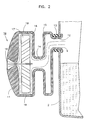
- the air-freshener device illustrated in Figs. 1 and 2 utilizes the second opening in the water supply tank, designated 9 in Figs. 1 and 2, normally not used for the water supply pipe 4 and therefore normally plugged, for attaching the air-freshener device, generally designated 10.
- the air-freshener device 10 comprises a housing 11 integrally formed with a cylindrical mounting fitting 12 for mounting the housing within opening 9 of the water tank 2.
- Fitting 12 further includes a sealing ring 13 for sealing the connection of the housing to the water supply tank.
- Housing 11 is of generally cylindrical configuration but is reduced in diameter at a mid-portion defining a restrictor passageway 14 connecting a first housing chamber 15 to a second housing chamber 16.
- Chamber 16 receives an air-freshener body 17 also of substantially cylindrical configuration.
- Housing 11 is formed with a large opening 18 extending axially of the air-freshener body 17, and a plurality of small openings 19 extending through the circumferential wall of the housing around the air-freshener body.
- the mounting fitting 12 of the air-freshener device 10 establishes communication between the interior of the upper end of the water tank 2 and the interior of housing 11.
- air is drawn via openings 18 and 19 through housing 11 of the air-freshener device 10 and into the upper end of the water tank.
- the air drawn into the water tank flows around the air-freshener body 17 within housing chamber 16 and thereby becomes loaded with the air-freshener substance of that body.
- the water tank is filled with ambient air loaded with the water freshener substance of body 17.
- Restrictor passageway 14 increases the velocity of the air as it passes around the air-freshener body 17.
- the volume of chamber 16 is only slightly larger than the volume of the air-freshener body 17, so that a large surface area of body 17 is exposed to the air passing through that chamber.
- the air-freshener body 17 is exposed to ambient air both during the flushing phase, when the water tank 2 is filled with air by the emptying of the water from the tank, and also during the refilling phase when the air within the water tank is expelled by the refilling of the water tank with water.
- this exposure of the air-freshener body to the air is sufficient despite some air leakage between the lid 3 and the water supply tank 2.
- a sealing ring shown schematically at 20 in Fig. 1, may be provided between the upper end of the water supply tank 2 and the lid 3.
- the air-freshener device 10 may be constructed as a disposable unit to be replaced when the air-freshener body 17 has been substantially exhausted. Alternatively, it may be constructed as a refillable unit in which the air-freshener body 17 alone is to be replaced by a new body. This may be done by forming the respective end wall of the housing 11 as a removable cap enabling it to be removed, to provide access into chamber 16 for removing and exhausted air-freshener body and replacing it with a fresh one.
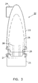
- Fig. 3 illustrates another construction that may be used for the air-freshener device, therein designated 22.
- the device includes a housing 23 integrally formed at its upper end with cylindrical fitting 24 for mounting the housing within opening 9 of the water tank, and a removable base 25 at its lower end carrying the air-freshener body 26.
- Body 25 is integrally formed with a plurality of ribs 27 received within recesses 28 formed in the inner surface of housing section 23.
- Ribs 27 and recesses 28 are dimensioned such that the base 25 can be spaced from the lower end of housing section 23 to provide the air passageways for the ambient air to enter the housing during the flushing of the water, or to be expelled from the housing during the refilling of the tank.
- Ribs 27 and recess 28 also permit base 25 to be moved to a closed position against the lower end of housing 23, in order to prevent dissipation of the air-freshener body 26.
- FIGs. 4 and 5 illustrate a further form of air-freshener device, generally designated 30, constructed in accordance with the invention which may also be attached to the water tank 2 of a toilet flushing system for automatically freshening the air upon the actuation of the flushing system.
- the air-freshener device 30 illustrated in Figs. 3 and 4 also includes a housing 31 integrally formed at one end with a cylindrical mounting fitting 32 for mounting the device within opening 9 (Fig. 1) of the water tank, in order to establish communication between the interior of the housing 31 and the upper end of the water tank.
- Fitting 32 includes a sealing ring 33 for sealing this connection.
- housing 31 The interior of housing 31 is divided by a wall 34 into a first chamber 35 adjacent to fitting 32, and a second chamber 36 containing the air-freshener body 37.
- Chamber 36 is divided into two sub-chambers or sections 36a, 36b, by a partition wall 36c.
- the air-freshener body 37 is also divided by partition wall 36c into a first section 37a within chamber section 36a, and a second section 37b within chamber section 36b.
- Housing 31 is also formed in two sections, namely a small-diameter section 31a adjacent to the mounting fitting 32 and defining chamber 35, and a large-diameter section 31b received over the outer circumference of partition wall 36c.
- housing section 31b and the partition wall 36c define the chamber section 36b receiving the air-freshener body section 37b.
- the end wall of housing section 31b is formed with a large opening 38 extending axially with respect to the air-freshener body, and a plurality of smaller openings 39 extending around section 37b of the air-freshener body.
- the small-diameter section 31a of housing 31 terminates short of partition wall 36c so as to define an annular opening 40 between the two housing sections and communicating with chamber section 36a of the housing receiving the air-freshener body section 37a.
- the two sections 37a, 37b of the air-freshener body 37 are enclosed within a screen 41 permeable by air to expose the air-freshener susbstance within body 37 to the air flowing through chamber sections 36a and 36b.
- the air-freshener body 37 including its screen enclosure 41, is carried by partition wall 36c, and is provided with a plurality of axially-extending, circumferentially-spaced spacer elements 42 for spacing the screen enclosure 41 from partition wall 34.
- Housing section 31b is formed with an annular rib 43 on its inner surface engageable with wall 36c for mounting that housing section to the wall.
- Screen enclosure 41 of the air-freshener body 37 includes an annular ring engageable with an annular rib 44 formed on the inner surface of housing section 31a for securing wall 36c, and the air-freshener body 37 carried thereby, to housing section 31a.
- Chamber 35 adjacent to fitting 32 mounting the device to the water tank includes an impeller, generally designated 50, for rotating a fan 51 located within chamber section 36b.
- Fan 51 force-circulates the air from opening 38 around the air-freshener body section 37b and out through openings 39.
- impeller 50 includes a cylindrical housing 52 formed with a plurality of tangential openings 53 to produce a cyclonic flow of the air through the interior of housing 52 to impinge a plurality of impeller vanes 54. These vanes are fixed to a shaft 55 extending axially of the housing and coupled to the fan blades 51 within chamber section 36b at the opposite end of the housing for force-circulating the air through the air-freshener body section 37b and out through openings 39.
- the rising level of the water forces the air within the upper end of the tank, previously loaded with the air-freshener substance during the flushing phase, to flow via fitting 32 through the turbine 50, its openings 53, restrictor passage 34a, around the air-freshener body section 37a, and out through the annular opening 40 from the housing, thereby discharging refreshed air also during the refilling phase.
- the fan 51 is not rotated during this refilling phase.
- fan 51 may also be driven during the refilling phase to force-circulate the air past air-freshener body section 37b and out through openings 39.
Landscapes
- Health & Medical Sciences (AREA)
- Public Health (AREA)
- Epidemiology (AREA)
- Life Sciences & Earth Sciences (AREA)
- Engineering & Computer Science (AREA)
- Hydrology & Water Resources (AREA)
- Water Supply & Treatment (AREA)
- Animal Behavior & Ethology (AREA)
- General Health & Medical Sciences (AREA)
- Veterinary Medicine (AREA)
- Disinfection, Sterilisation Or Deodorisation Of Air (AREA)
Applications Claiming Priority (2)
| Application Number | Priority Date | Filing Date | Title |
|---|---|---|---|
| IL11286795 | 1995-03-02 | ||
| IL11286795A IL112867A0 (en) | 1995-03-02 | 1995-03-02 | Method and device for freshening the air adjacent to toilets |
Publications (2)
| Publication Number | Publication Date |
|---|---|
| EP0730065A2 true EP0730065A2 (fr) | 1996-09-04 |
| EP0730065A3 EP0730065A3 (fr) | 1997-07-09 |
Family
ID=11067168
Family Applications (1)
| Application Number | Title | Priority Date | Filing Date |
|---|---|---|---|
| EP96103161A Withdrawn EP0730065A3 (fr) | 1995-03-02 | 1996-03-01 | Dispositif de rafraîchissement de l'air adjacent aux toilettes |
Country Status (2)
| Country | Link |
|---|---|
| EP (1) | EP0730065A3 (fr) |
| IL (1) | IL112867A0 (fr) |
Cited By (5)
| Publication number | Priority date | Publication date | Assignee | Title |
|---|---|---|---|---|
| FR2876915A1 (fr) * | 2004-10-26 | 2006-04-28 | Patrice Miquelis | Appareil de diffusion de senteurs et/ou d'agents desinfectants pour un local sanitaire |
| US7721358B2 (en) | 2007-09-11 | 2010-05-25 | The Clorox Company | Toilet device with improved fragrance delivery |
| US8266728B2 (en) | 2007-08-21 | 2012-09-18 | The Clorox Company | Toilet device with cleanser and fragrance |
| US8307467B2 (en) | 2007-08-23 | 2012-11-13 | The Clorox Company | Toilet device with indicator |
| FR3009727A1 (fr) * | 2013-08-13 | 2015-02-20 | Nordine Recham | Systeme de chasse d'eau creant un flux d'air afin de se substituer a tout aerosol pour desodoriser |
Family Cites Families (9)
| Publication number | Priority date | Publication date | Assignee | Title |
|---|---|---|---|---|
| GB782872A (en) * | 1955-08-10 | 1957-09-11 | Calmic Ltd | An improved method and apparatus for deodorising the atmosphere |
| GB918218A (en) * | 1961-09-14 | 1963-02-13 | Howell David | Improvements in sanitary appliances |
| US3327325A (en) * | 1965-04-20 | 1967-06-27 | Albert J Roger | Lavatory perfumer |
| GB1093748A (en) * | 1965-05-06 | 1967-12-06 | Statter Projects Pty Ltd | Water-closet ventilating apparatus comprising a fan |
| FR2036149A5 (fr) * | 1969-03-05 | 1970-12-24 | Henry Georges | |
| US3927429A (en) * | 1974-01-18 | 1975-12-23 | Raymond H Pearson | Toilet deodorizing accessory including leak proof connection |
| US3914805A (en) * | 1974-04-08 | 1975-10-28 | John E Dolan | Automatic room deodorizing device |
| US4212089A (en) * | 1979-04-24 | 1980-07-15 | International Flavors & Fragrances Inc. | Process for aromatizing and/or deodorizing the environment surrounding the flush tank of a toilet |
| WO1982003883A1 (fr) * | 1981-05-06 | 1982-11-11 | Jack Kenneth Ibbott | Dispositif desodorisant |
-
1995
- 1995-03-02 IL IL11286795A patent/IL112867A0/xx unknown
-
1996
- 1996-03-01 EP EP96103161A patent/EP0730065A3/fr not_active Withdrawn
Cited By (5)
| Publication number | Priority date | Publication date | Assignee | Title |
|---|---|---|---|---|
| FR2876915A1 (fr) * | 2004-10-26 | 2006-04-28 | Patrice Miquelis | Appareil de diffusion de senteurs et/ou d'agents desinfectants pour un local sanitaire |
| US8266728B2 (en) | 2007-08-21 | 2012-09-18 | The Clorox Company | Toilet device with cleanser and fragrance |
| US8307467B2 (en) | 2007-08-23 | 2012-11-13 | The Clorox Company | Toilet device with indicator |
| US7721358B2 (en) | 2007-09-11 | 2010-05-25 | The Clorox Company | Toilet device with improved fragrance delivery |
| FR3009727A1 (fr) * | 2013-08-13 | 2015-02-20 | Nordine Recham | Systeme de chasse d'eau creant un flux d'air afin de se substituer a tout aerosol pour desodoriser |
Also Published As
| Publication number | Publication date |
|---|---|
| IL112867A0 (en) | 1995-06-29 |
| EP0730065A3 (fr) | 1997-07-09 |
Similar Documents
| Publication | Publication Date | Title |
|---|---|---|
| US6434758B2 (en) | Cleansing and freshening unit intended for suspension from a rim of a toilet bowl | |
| US6694534B2 (en) | Toilet ventilation system | |
| US6662379B2 (en) | Toilet cleaning dispenser system with removable cartridge | |
| US6526598B1 (en) | Self-contained venting toilet | |
| SI20190A (sl) | Uparjalni svežilec zraka | |
| US5125119A (en) | Odor reduction toilet apparatus | |
| US3857119A (en) | Ventilating attachment for water closet | |
| EP0857242B2 (fr) | Piege a odeurs pour conduits d'evacuation, a ecoulement horizontal, preservant l'huile d'etancheite | |
| BG63757B1 (bg) | Устройство за изпускане на отпадъчни продукти | |
| US5689837A (en) | Water actuated toilet fan | |
| EP0730065A2 (fr) | Dispositif de rafraîchissement de l'air adjacent aux toilettes | |
| US20090064401A1 (en) | Toilet Device With Improved Fragrance Delivery | |
| US3913151A (en) | Apparatus for dispensing metered quantity of liquid | |
| US20020116752A1 (en) | Automatic toilet cleaning dispenser assembly | |
| JPH03132530A (ja) | 洗浄タンク | |
| JP4847443B2 (ja) | 大便器用排気装置及び洗浄装置 | |
| JPH10137635A (ja) | 芳香剤を備えた吐水具 | |
| KR200401803Y1 (ko) | 좌변기의 악취 배출장치 | |
| GB2372263A (en) | Odour extraction system for a toilet bowl or urinal | |
| WO1982003883A1 (fr) | Dispositif desodorisant | |
| EP1556556A1 (fr) | Distributeur de liquide destine a etre place dans un volume de liquide a niveau variable, en particulier pour la distribution mesuree de produits chimiques dans une citerne | |
| US5718261A (en) | Cleaning solution dispenser for use in a water tank, and water tank capable of discharging mixture of water and cleaning solution | |
| EP0109151B1 (fr) | Dispositif de distribution | |
| CN116254902B (zh) | 一种除臭装置及马桶 | |
| CN215105828U (zh) | 一种旋转小便池 |
Legal Events
| Date | Code | Title | Description |
|---|---|---|---|
| PUAI | Public reference made under article 153(3) epc to a published international application that has entered the european phase |
Free format text: ORIGINAL CODE: 0009012 |
|
| AK | Designated contracting states |
Kind code of ref document: A2 Designated state(s): CH DE ES FR IT LI NL |
|
| PUAL | Search report despatched |
Free format text: ORIGINAL CODE: 0009013 |
|
| AK | Designated contracting states |
Kind code of ref document: A3 Designated state(s): CH DE ES FR IT LI NL |
|
| STAA | Information on the status of an ep patent application or granted ep patent |
Free format text: STATUS: THE APPLICATION IS DEEMED TO BE WITHDRAWN |
|
| 18D | Application deemed to be withdrawn |
Effective date: 19980110 |