EP0730281A2 - Bearbeitung des Drahtendes eines drahtgewickeltem Widerstands - Google Patents
Bearbeitung des Drahtendes eines drahtgewickeltem Widerstands Download PDFInfo
- Publication number
- EP0730281A2 EP0730281A2 EP96103071A EP96103071A EP0730281A2 EP 0730281 A2 EP0730281 A2 EP 0730281A2 EP 96103071 A EP96103071 A EP 96103071A EP 96103071 A EP96103071 A EP 96103071A EP 0730281 A2 EP0730281 A2 EP 0730281A2
- Authority
- EP
- European Patent Office
- Prior art keywords
- resistance wire
- wound
- portions
- wound resistance
- compressing
- Prior art date
- Legal status (The legal status is an assumption and is not a legal conclusion. Google has not performed a legal analysis and makes no representation as to the accuracy of the status listed.)
- Withdrawn
Links
Images




Classifications
-
- H—ELECTRICITY
- H01—ELECTRIC ELEMENTS
- H01C—RESISTORS
- H01C3/00—Non-adjustable metal resistors made of wire or ribbon, e.g. coiled, woven or formed as grids
- H01C3/14—Non-adjustable metal resistors made of wire or ribbon, e.g. coiled, woven or formed as grids the resistive element being formed in two or more coils or loops continuously wound as a spiral, helical or toroidal winding
- H01C3/20—Non-adjustable metal resistors made of wire or ribbon, e.g. coiled, woven or formed as grids the resistive element being formed in two or more coils or loops continuously wound as a spiral, helical or toroidal winding wound on cylindrical or prismatic base
Definitions
- the wire comprises a resistance wire element wound onto a core of a thermoplastic resin.
- An insulating member covers an outer periphery of the wire element.
- a wound resistance wire can be used, for example, in the wiring of an ignition plug system in a vehicle.
- a wound resistance wire can be produced by winding a resistance wire element onto a core of a thermoplastic resin such as a fluoro rubber. An insulating member is then extruded onto an outer periphery of the wire element-wound core.
- the end of a wound resistance wire can be processed by an end processing apparatus as shown in Fig. 6.
- the end processing apparatus comprises a cutting section 10 for cutting a continuously-fed wound resistance wire 15 into a predetermined length, a stripping section 11 for removing an insulating member from opposite ends of a cut length of wound resistance wire 15, thereby forming exposed portions each defined by a core having a resistance wire element wound thereon, a heating/compressing section 12 for heating and compressing each exposed portion, a dag coating section 13 for coating the thus heated and compressed, exposed portions with dag, and a dag drying section 14 for drying the dag coated onto the exposed portions.
- Cutting by section 10 and stripping by section 11 are effected by conventional techniques.
- Heating/compressing section 12 is similar to that disclosed in Japanese Patent Unexamined Publication No. 3-70416 filed by the Applicant of the present application.
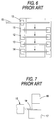
- section 12 comprises a lower die 17 fixed at a predetermined position, and an upper die 18 vertically movable between an upper position indicated by a solid line and a lower position indicated by a broken line (see Fig. 7).
- the upper die 18 contains a heater (not shown) for heating upper die 18.
- an end portion of the exposed portion 19 of wound resistance wire 15 is placed on the upper surface of the lower die 17. Then the upper die 18 moves downward to its lower position to compress only an upper portion of a distal end portion of the exposed portion 19 in the vertical direction.
- exposed portion 19 is heated by die 18.
- the distal end portion of the exposed portion of resistance wire element 20 is embedded into core 21 of thermoplastic resin so as to tightly wrap the core to prevent loosening of the wire element 20 as shown in Fig. 8.
- Exposed portion 19 is compressed in the vertical direction by the upper and lower dies 18 and 17. Heating is effected only by upper die 18.
- resistance wire element 20, pressed by the upper die 18, is embedded deeply into the upper side of the core 21.
- resistance wire element 20 is not embedded as deeply into the lower side of the core 21.
- the resistance wire element 20 can become loosened at the lower side.
- a dag 23 of an electrically-conductive carbon coating must be applied to assure that element 20 is tightly wrapped to prevent loosening at the lower side of core 21.
- the electrically-conductive carbon coating of the dag is coated onto exposed portion 19 as shown in Fig. 9. A blast of hot air is blown onto the coated dag 23 to dry the same as shown in Fig. 10 to prevent loosening of resistance wire element 20.
- the present invention provides a method of processing an end of a wound resistance wire comprising a resistance wire element wound on a core of a thermoplastic resin, and an insulating member covering an outer periphery of the wire element-wound core.
- the method comprises the steps of: removing insulating member from an end portion of the wound resistance wire, thereby forming an exposed portion comprising an exposed core portion having a wound resistance wire element; and heating and compressing both upper and lower portions of the exposed core portion to embed wound resistance wire element into both upper and lower portions.
- both upper and lower portions of the exposed portion are heated and compressed.
- the core is thermoplastically deformed at upper and lower sides of the exposed portion so that the resistance wire element is embedded in both the upper and lower sides of the core.
- the wound resistance wire 36 includes a resistance wire element 31 wound on a core 30 made of a fluoro rubber containing ferrite.
- An insulating member 32 is extruded onto an outer periphery of the wire element-wound core 30.
- the end processing apparatus for processing the wound resistance wire comprises a cutting section 33, a stripping section 34, and an opposite-side heating/compressing section 35, which are arranged in this order or sequence from an upstream side (that is, from an upper side) in Fig. 2.
- Cutting section 33 and stripping section 34 are of conventional construction.
- the resistance wire 36 is continuously fed from the left.
- the wire 36 is cut into a predetermined length by the cutting section 33.
- a cut length of wound resistance wire 36 is transferred to stripping section 34 where part of insulating member 32 is removed from opposite end portions of the cut portion to form exposed portions 37 each defined by core 30 having resistance wire element 31 wound thereon (see Fig. 1).
- wound resistance wire 36 is transferred to opposite-side heating/compressing section 35 where upper and lower portions of each exposed portion 37 are heated and compressed.
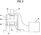
- opposite-side heating/compressing section 35 comprises a cylinder 42 mounted on an upper portion of an upper base 41, an upper die 44, which is mounted on a distal end of a piston rod 43 of the cylinder 42, and containing a heater (not shown), a lower die 47, which is mounted through a heat-insulating member 46 on a lower die base 45 provided generally centrally of the height of the upper base 41, and containing a heater (not shown), and a temperature control section 48 for controlling the temperature of the heaters contained respectively in the upper and lower dies 44 and 47.
- Upper die 44 is moved upwardly and downwardly by cylinder 42 by means of piston rod 43 between an upper position (indicated by a solid line in Fig. 4) above the lower die base 45 and a lower position (indicated by a broken line in Fig. 4) close to the lower die base 45.
- upper die 44 is in an upper position, each exposed portion 37 of the wound resistance wire 36 is placed on lower die 47, and upper die 44 is moved to its lower position.
- a distal end portion of exposed portion 37 is heated and compressed by the lower surface of upper die 44 and the upper surface of the lower die 47, so that resistance wire element 31 is embedded into both upper and lower sides of core 30, thus forming a compressed portion 37b.
- Resistance wire element 31 at each exposed portion 37 is embedded onto both upper and lower sides of core 30. Resistance wire element 31 cannot become loosened. Further, no dag coat is required to prevent loosening as is required with wire ends produced by a conventional method such as shown in Figures 6-10. Therefore, end processing according to the invention can be carried out by the use of a simply constructed apparatus.
- Core 30 is shown as made of fluoro rubber containing ferrite.
- core 30 may be any other suitable thermoplastic resin such as chlorinated polyethylene, polyolefin resin, ethylene-propylene-diene terpolymer or silicone rubber.
- Temperature of upper die 44 and lower die 47, as well as thickness of the compressed portion 37b, can be changed in accordance with the material used for core 30 and with the diameter of the core.
- core 30 is composed of fluoro rubber containing ferrite.
- temperature of the upper and lower dies 44 and 47 is set to 120°C
- thickness of the compressed portion 37b is set to 0.5-0.7 mm.
- the diameter of the core 30 is 1.1 mm
- the temperature of the two dies is set to 80°
- the thickness of the compressed portion 37b is set to 0.5 ⁇ 0.7 mm.
- Resistance wire element 31 is wound on that portion of the exposed portion 37 extending from its lengthwise central portion to its proximal end. Only the distal end portion of exposed portion 37 needs to be heated and compressed as shown for resistance wire element 31 to make electrical contact when a terminal is clamped to the end portion of the wire.
Landscapes
- Engineering & Computer Science (AREA)
- Microelectronics & Electronic Packaging (AREA)
- Resistance Heating (AREA)
- Processing Of Terminals (AREA)
Applications Claiming Priority (2)
| Application Number | Priority Date | Filing Date | Title |
|---|---|---|---|
| JP44455/95 | 1995-03-03 | ||
| JP7044455A JPH08251749A (ja) | 1995-03-03 | 1995-03-03 | 巻線型抵抗電線の端末処理方法 |
Publications (2)
| Publication Number | Publication Date |
|---|---|
| EP0730281A2 true EP0730281A2 (de) | 1996-09-04 |
| EP0730281A3 EP0730281A3 (de) | 1997-06-04 |
Family
ID=12691971
Family Applications (1)
| Application Number | Title | Priority Date | Filing Date |
|---|---|---|---|
| EP96103071A Withdrawn EP0730281A3 (de) | 1995-03-03 | 1996-02-29 | Bearbeitung des Drahtendes eines drahtgewickeltem Widerstands |
Country Status (5)
| Country | Link |
|---|---|
| EP (1) | EP0730281A3 (de) |
| JP (1) | JPH08251749A (de) |
| CN (1) | CN1044527C (de) |
| AU (1) | AU676976B2 (de) |
| BR (1) | BR9600879A (de) |
Families Citing this family (1)
| Publication number | Priority date | Publication date | Assignee | Title |
|---|---|---|---|---|
| JP4765569B2 (ja) * | 2005-11-16 | 2011-09-07 | 株式会社デンソー | 負荷電流制御用抵抗器の組み立て方法 |
Family Cites Families (7)
| Publication number | Priority date | Publication date | Assignee | Title |
|---|---|---|---|---|
| DE1816517B2 (de) * | 1967-12-22 | 1972-01-20 | Remix Radiotechmkai Vallalat, Budapest | Vorrichtung zur herstellung von einlagigen elektrischen wicklungen |
| US3813643A (en) * | 1971-10-28 | 1974-05-28 | Essex International Inc | Terminating of electrical conductors |
| US4621251A (en) * | 1985-03-28 | 1986-11-04 | North American Philips Corp. | Electric resistance heater assembly |
| DE3542227A1 (de) * | 1985-11-29 | 1987-06-04 | Oelsch Kg | Verfahren zur herstellung von potentiometerwiderstaenden |
| JPH0681395B2 (ja) * | 1989-08-07 | 1994-10-12 | 住友電装株式会社 | 巻線型雑音防止抵抗電線の端末加工方法 |
| JP2772307B2 (ja) * | 1992-04-16 | 1998-07-02 | 矢崎総業株式会社 | 雑音防止用高圧抵抗電線 |
| WO1994005485A1 (en) * | 1992-09-08 | 1994-03-17 | E. O. Butts Consultants Ltd. | Electric fusion welding of thermoplastic materials |
-
1995
- 1995-03-03 JP JP7044455A patent/JPH08251749A/ja active Pending
-
1996
- 1996-02-28 CN CN 96100009 patent/CN1044527C/zh not_active Expired - Fee Related
- 1996-02-29 AU AU45835/96A patent/AU676976B2/en not_active Ceased
- 1996-02-29 EP EP96103071A patent/EP0730281A3/de not_active Withdrawn
- 1996-03-01 BR BR9600879A patent/BR9600879A/pt not_active IP Right Cessation
Also Published As
| Publication number | Publication date |
|---|---|
| JPH08251749A (ja) | 1996-09-27 |
| AU4583596A (en) | 1996-09-26 |
| CN1135083A (zh) | 1996-11-06 |
| BR9600879A (pt) | 1997-12-30 |
| EP0730281A3 (de) | 1997-06-04 |
| AU676976B2 (en) | 1997-03-27 |
| CN1044527C (zh) | 1999-08-04 |
Similar Documents
| Publication | Publication Date | Title |
|---|---|---|
| US5579575A (en) | Method and apparatus for forming an electrical connection | |
| US4084307A (en) | Method of joining two cables with an insulation of cross-linked polyethylene or another cross linked linear polymer | |
| US4993149A (en) | Process for forming a termination on an electrical conductor | |
| EP0420480A2 (de) | Verfahren zum Anschliessen eines elektrischen Leitungsdrahtes | |
| AU1647295A (en) | Method of manufacturing an electrofusion coupler | |
| EP0730281A2 (de) | Bearbeitung des Drahtendes eines drahtgewickeltem Widerstands | |
| EP0067681B1 (de) | Endverschluss für Vorrichtungen mit leitenden Polymeren | |
| EP0615661A1 (de) | Elktrischer verbinder. | |
| JPS63168915A (ja) | 巻線型雑音防止抵抗電線の製造方法 | |
| JP2633722B2 (ja) | 電線の端末心線折り曲げ装置 | |
| IE920171A1 (en) | A method of welding cable insulation | |
| US4552988A (en) | Strippable insulated wire and method of making same | |
| US5046240A (en) | Method of terminating wire wound type noise preventing resistance cable | |
| JP2789583B2 (ja) | ケーブル接続部の成形方法 | |
| WO1993017467A1 (en) | Electrical connector | |
| JPH07170623A (ja) | ケーブルの端末処理方法 | |
| JPH0638390Y2 (ja) | ヒータの接続構造 | |
| JP2000152453A (ja) | 電力ケーブルの端末処理方法 | |
| CA2205638A1 (en) | Flexible heat tracing cable with improved thermal characteristics | |
| JPS6215985Y2 (de) | ||
| JPH0515032A (ja) | ケーブル接続部接続処理方法 | |
| EP0169648A2 (de) | Herstellung von elektrischen Kabeln | |
| JP2022077124A (ja) | 止水構造及び止水方法 | |
| JPS6057657B2 (ja) | 絶縁ケ−ブルの接続部の形成方法 | |
| JPS6219006B2 (de) |
Legal Events
| Date | Code | Title | Description |
|---|---|---|---|
| PUAI | Public reference made under article 153(3) epc to a published international application that has entered the european phase |
Free format text: ORIGINAL CODE: 0009012 |
|
| AK | Designated contracting states |
Kind code of ref document: A2 Designated state(s): DE FR GB |
|
| PUAL | Search report despatched |
Free format text: ORIGINAL CODE: 0009013 |
|
| AK | Designated contracting states |
Kind code of ref document: A3 Designated state(s): DE FR GB |
|
| 17P | Request for examination filed |
Effective date: 19970616 |
|
| GRAG | Despatch of communication of intention to grant |
Free format text: ORIGINAL CODE: EPIDOS AGRA |
|
| 17Q | First examination report despatched |
Effective date: 20010724 |
|
| GRAG | Despatch of communication of intention to grant |
Free format text: ORIGINAL CODE: EPIDOS AGRA |
|
| GRAH | Despatch of communication of intention to grant a patent |
Free format text: ORIGINAL CODE: EPIDOS IGRA |
|
| STAA | Information on the status of an ep patent application or granted ep patent |
Free format text: STATUS: THE APPLICATION IS DEEMED TO BE WITHDRAWN |
|
| 18D | Application deemed to be withdrawn |
Effective date: 20020108 |