EP0730386A2 - Conversion de format de couleur dans un processeur parallèle - Google Patents
Conversion de format de couleur dans un processeur parallèle Download PDFInfo
- Publication number
- EP0730386A2 EP0730386A2 EP96301431A EP96301431A EP0730386A2 EP 0730386 A2 EP0730386 A2 EP 0730386A2 EP 96301431 A EP96301431 A EP 96301431A EP 96301431 A EP96301431 A EP 96301431A EP 0730386 A2 EP0730386 A2 EP 0730386A2
- Authority
- EP
- European Patent Office
- Prior art keywords
- component
- color
- chrominance
- word
- luminance
- Prior art date
- Legal status (The legal status is an assumption and is not a legal conclusion. Google has not performed a legal analysis and makes no representation as to the accuracy of the status listed.)
- Granted
Links
Images


Classifications
-
- H—ELECTRICITY
- H04—ELECTRIC COMMUNICATION TECHNIQUE
- H04N—PICTORIAL COMMUNICATION, e.g. TELEVISION
- H04N9/00—Details of colour television systems
- H04N9/64—Circuits for processing colour signals
- H04N9/641—Multi-purpose receivers, e.g. for auxiliary information
Definitions
- the present invention relates to conversion of video signals from one format to another and, in particular, to conversion of video signals from YUV format to a color component or similar format using a parallel processor.
- Color video images are rendered on televisions and computer display screens using three component colors, typically, red, green, and blue.
- Video signals representing red, green, and blue components of a pixel are in "RGB" format.
- Video signals in RGB format typically include the same amount of information for each of the component colors, i.e., for each of red, green, and blue.
- Other, similar color component formats e.g., cyan, magenta and yellow (CMY), are also used.
- Video signals are frequently transmitted, e.g., either through frequency-modulated RF signals for reception by conventional televisions or through computer networks for display on a computer display screen, in a YUV format
- YUV format takes advantage of the fact that human eyes are more sensitive to luminance information and less sensitive to chrominance information
- Video signals in YUV format generally include up to twice as much luminance information as chrominance information.
- "Y" in YUV generally represents the luminance information and is the only component of a video signal displayed by conventional black-and-white televisions and computer display screens capable of no more than greyscale video displays.
- U and V in YUV are chrominance signals and represent two separate color components of the color video signal
- a color video signal in YUV format is converted to a color video signal in another format, in particular, RGB format, according to the following well-known equation.
- Conversion of video signals from YUV format to other formats, e.g., CMY, is accomplished by other, similar, well-known equations
- Conversion of video signals representing pixels in YUV format to video signals in RGB format according to equation (1) requires several multiplication and addition operations per pixel and general requires approximately 20 instruction cycles of a processor performing such color format conversion.
- a digital NTSC television signal generates approximately 10.4 million pixels per second, and to convert the video signals of a digital NTSC television signal from YUV format to RGB format using even the fastest conventional microprocessors requires approximately 200 million instruction cycles per second, i.e, nearly all of the data processing bandwidth of such a microprocessor
- Decompression of motion video signals which have been compressed according to the MPEG compressed video standards for transport through computer networks, for example, includes conversion of video signals from YUV format to a format suitable for display, e.g., RGB format.
- MPEG2 MPEG compressed video standards
- luminance and chrominance signals are used to form luminance and chrominance component words which include partitioned words representing various color components of the luminance and chrominance signals
- the luminance and chrominance component words are summed using a partitioned addition operation to thereby accumulate the various color components of the luminance and chrominance signals simultaneously and in parallel using a number of processing sub-units of a graphics execution unit. Accumulation of color components in parallel substantially reduces the number of instruction cycles required to convert pixels of a color image from YUV format to a different format.
- formation of the luminance and chrominance component words is done by a load and store unit of a central processing unit while the graphics execution unit, in the same central processing unit, simultaneously sums the luminance and chrominance components using the partitioned addition operation.
- the load and store unit retrieves from one or more tables of precalculated luminance and chrominance component words a luminance component word corresponding to a luminance signal of a pixel and a chrominance component word corresponding to a chrominance signal of the pixel.
- color converting in accordance with the present invention, conversion of an image from YUV format to a different format, e.g., RGB format, is reduced from approximately 20 instruction cycles per pixel to generally less than 2.5 instruction cycles per pixel.
- a different format e.g., RGB format
- the color conversion from YUV format to RGB format in the rendering of the color motion video image is reduced from 200 million instructions per second to generally less than 25 million instructions per second. Such is easily manageable by currently available processors, even those of unexceptional speed.
- Figure 1 is a logic flow diagram of a color conversion process in accordance with the present invention.
- Figure 2 is a block diagram illustrating a partitioned multiplication operation to form luminance and chrominance component words in accordance with the present invention.
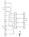
- Figure 3 is a block diagram illustrating a partitioned addition operation to form color component words in accordance with the present invention.
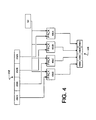
- Figure 4 is a block diagram illustrating a partitioned packing operation to scale and clip segments of the color component word formed in accordance with Figure 3.
- Figures 5A-C are block diagrams of tables from which luminance and chrominance component data words are retrieved.
- Figure 6 is a block diagram of a central processing unit including a graphics execution unit capable of executing the partitioned multiplication and addition operations of Figures 2 and 3, respectively.
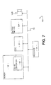
- Figure 7 is a block diagram of a computer system in accordance with the present invention and which includes the central processing unit of Figure 6.
- Figure 8 is a block diagram of a color converter of the computer system of Figure 7.
- Logic flow diagram 100 ( Figure 1) illustrates the conversion of a color pixel from YUV format to RGB format. The steps of logic flow diagram 100 are performed within a central processing unit of a computer and are equally applicable to conversion of a pixel from YUV format to another destination format, e.g., CMY.
- step 102 luminance and chrominance signals corresponding to the color pixel are retrieved using conventional techniques.
- step 104 luminance and chrominance component words are formed from the retrieved luminance and chrominance signals.
- a component word is a data word including partitioned segments, each of which represents a component of the represented signal.
- a luminance component word includes partitioned segments representing respective components of a luminance signal.
- a luminance component word includes partitioned segments representing red, green, and blue components of a luminance signal.
- steps 104R, 104G. and 104B red, green, and blue components, respectively, of the luminance and chrominance component words are accumulated simultaneously and in parallel to form red, green, and blue components, respectively, of a color component word.
- a color component word includes partitioned segments representing color components of a color pixel, e.g., red, green, and blue components of a color pixel in RGB format. From steps 104G, 104G, and 104B, processing transfers in parallel to steps 106R, 106G, and 106B, respectively, in which each partitioned segment representing a color component of the color pixel is scaled and clipping so as to be in the destination format. For example, red, green, and blue components of the color component word are scaled and clipped into a commonly-used 8-bit, unsigned integer RGB format in steps 106R, 106G, and 106B, respectively.
- Equation (1 ) above is re-written as follows to better illustrate processing according to logic flow diagram 100.
- Figure 2 illustrates the processing of color components of a luminance signal, for example, of a color image pixel in YUV format.
- a register 202 is partitioned into a number of segments. In one embodiment, register 202 is 64 bits in length and is partitioned into four (4) 16-bit, fixed point segments 202A-D.
- a coefficient corresponding to red, green, and blue components of the luminance signal are stored in segments 202C, 202B, and 202A, respectively, of register 202. From equation (2) above, the red, green, and blue coefficients of the luminance signal each have a value of approximately 1.1644.
- Adjusted luminance data is stored in a register 204.
- the adjusted luminance data is represented by an 8-bit, unsigned integer.
- the adjusted luminance data is represent by a 16-bit, fixed point number
- the adjusted luminance data has a value equal to sixteen (16) less than the value of the luminance signal represented as data having a value between 0 and 255, as shown in equation (2) above.
- Each of segments 202A-D is coupled to an input of a respective one of processing sub-units 205A-D.
- Processing sub-units 206A-D are included in a graphics execution unit (not shown in Figure 2) of the central processing unit (also not shown in Figure 2), all of which are described below in greater detail with respect to Figure 6 and in the '572 application.
- Register 204 is coupled to a respective input of each of processing sub-units 206A-D, which operate in a multiplication mode simultaneously and in parallel to multiply data stored in register 204 by data stored in segments 202A-D, respectively, of register 202 in a "partitioned multiplication operation".
- the results of such multiplication are stored in respective partitioned segments 208A-D of a register 208, which are coupled to outputs of processing sub-units 206A-D, respectively.
- Register 208 is partitioned as described above with respect to register 202.
- data representing three color components of the luminance signal are produced by processing sub-units 206A-C and are stored in segments 208A-C of register 208.
- red, green and blue component coefficients from equation (2) above are stored in segments 202C, 202B, and 202A, respectively.
- Operation of processing sub-units 206C, 206B, and 206A for one instruction cycle in multiplication mode produces red, green and blue components, respectively, of the luminance signal.
- Red, green, and blue components of a U chrominance signal are derived in an analogous manner Red, green, and blue components of a U chrominance signal are derived by (1) storing red, green, and blue component coefficients of the U chrominance signal in segments 202C, 202B, and 202A, respectively, (2) storing in register 204 adjusted U chrominance data, and (3) operating processing sub-units 206A-D in the multiplication mode for one instruction cycle As shown in equation (2) above, the red, green, and blue component coefficients for the U chrominance signal are approximately 0.0000, -0.3920, and 2.0184, respectively.
- the adjusted U chrominance data has a value equal to 128 less than the value of the U chrominance signal represented as data having a value between 0 and 255
- Red, green and blue components of the V chrominance signal are derived by (1) storing red, green, and blue component coefficients of the V chrominance signal in segments 202C, 202B, and 202A, respectively, (2) storing in register 204 adjusted V chrominance data, and (3) operating processing sub-units 206A-D in the multiplication mode for one instruction cycle.
- the red, green, and blue component coefficients for the V chrominance signal are approximately 1.5966 -0.8132, and 0.0000, respectively.
- the adjusted V chrominance data has a value equal to 128 less than the value of the V chrominance signal represented as data having a value between 0 and 255.
- the component words are accumulated to form a color component word. For example, to form a red component of a color pixel, the red components of the luminance, U chrominance, and V chrominance signals are summed. Summing of the luminance, U chrominance, and V chrominance component words is accomplished in the same graphics execution unit of the central processing unit described briefly above and more completely below and in the '572 application.
- Figure 3 shows substantially the same circuitry shown in Figure 2 with the circuitry configured slightly differently in Figure 3.
- Register 304 is partitioned into four (4) 16-bit fixed point registers 304A-D, each of which is coupled to an input of a respective one of processing sub-units 305A-D.
- Processing sub-units 306A-D are included in the graphics execution unit described briefly above and more completely below and operate in an addition mode to execute a "partitioned addition operation.” In the partitioned addition operation, processing sub-units 306A-D produce and store in segments 208A-D, respectively, of register 208 data representing the arithmetic sums of data stored in segments 202A-D, respectively, and segments 304A-D, respectively.
- a composite chrominance component word is formed by (1) storing in register 202 the U chrominance component word, (2) storing in register 304 the V chrominance component word, and (3) operating processing sub-units 306A-D in the addition mode for one instruction cycle.
- the result is red, green, and blue components of a composite chrominance component word stored in segments 208C, 208B, and 208A, respectively, of register 208.
- the composite chrominance component word is useful because, in the standard 4:2:0 YUV format, four pixels are represented by four separate luminance signals and only one U chrominance signal and only one V chrominance signal.
- the composite chrominance component word can therefore be used in conversion of four separate pixels from YUV 4:2:0 format to RGB format or some similar destination format, e.g., CMY. Consequently, to derive the composite chrominance component word for four (4) pixels of a color image requires two (2) partitioned multiplication operations as described above with respect to Figure 2, i.e., one for the U chrominance signal and one for the V chrominance signal, and one (1) partitioned addition operation as described above with respect to Figure 3.
- Red, green, and blue components of the color pixel in RGB format are derived by (1) storing the luminance component word in register 202, (2) storing the composite chrominance component word in register 304, and (3) operating processing sub-units 305A-D in the addition mode for one instruction cycle.
- red, green, and blue components of a color component word are produced and stored as 16-bit fixed point data in segments 208C, 208B, and 208A, respectively, of register 208.
- color component words for four (4) pixels of a color image requires, in addition to the operations required to derive the composite chrominance component word as described above, four (4) partitioned multiplication operations to form four (4) respective luminance component words anc four (4) partitioned addition operations to form four (4) respective color component words from the four respective luminance component words and a single composite chrominance component word.
- six (6) partitioned multiplication operations and five (5) partitioned addition operations are required to form four (4) color component words representing four (4) respective pixels of a color image in the destination format.
- component color information of a color pixel is stored in 8-bit, unsigned integer format. Conversion of three 16-bit fixed point color components of a pixel to three 8-bit unsigned integer color components of a pixel typically requires three multiplications and six comparisons. In general, a 16-bit fixed point number is converted to an 8-bit unsigned integer by multiplying the fixed point number by a scaling factor which scales such a fixed point number generally to a number in the range of 0 to 255. This scaling sometimes produces a number which is either less than zero or greater than 255.
- processing sub-units 406A-D which are included in the graphics execution unit described briefly above and more completely below, scale and clip data from each of segments 202A-D in a "partitioned packing operation."
- processing sub-units 406A-D scale 16-bit fixed point data of segments 202A-D, respectively, according to a scale factor stored in scale factor register 52, which is described more completely in the '572 application and which is coupled to respective inputs of processing sub-units 206A-D.
- processing sub-units 206A-D clip the scaled data to the range of values 0-255.
- the scaling and clipping process is performed by processing sub-units 206A-D in a single instruction cycle and is described more completely in the '572 application with respect to Figure 8b thereof, and that discussion is incorporated herein by reference.
- the results of the scaling and clipping of processing sub-units 206A-D are stored in 8-bit segments 408A-D, respectively, of register 408.
- 8-bit unsigned integers representing the red, green, and blue components of the pixel of the color image are stored in segments 408C, 4088, and 408A, respectively, of register 408.
- color component words are derived by reference to a table of precalculated component words thereby obviating the partitioned multiplication operations described above with respect to Figure 2.
- tables 42A-C are formed within data cache 42 (described below with respect to Figure 6)
- Table 42A is a luminance table and includes 256 records each of which is 48 bits in length.
- Each record includes three (3) 16-bit fixed point segments corresponding to three respective color components of a luminance signal.
- Each record in table 42A corresponds to a specific luminance signal.
- record 502 corresponds to a luminance signal having a value of "y" in the range of 0 to 255.
- Record 502 has color component segments 502C, 502B. and 502A, which in this example correspond to red, green, and blue components, respectively, of a luminance signal having a value of "y". From equation (2) above, segments 502C, 502B, and 502A each contain a 16-bit fixed point number having a value approximately equal to 1.1644(y-16). A luminance component word corresponding to a luminance signal is formed by retrieving a record from table 42A corresponding to the luminance signal.
- Table 42B ( Figure 5B) is a U chrominance table and includes 256 records each of which is 48 bits in length. Each record includes three (3) 16-bit fixed point segments corresponding to three respective color components of a U chrominance signal. Each record in table 42B corresponds to a specific U chrominance signal. For example, record 522 corresponds to a U chrominance signal having a value of "u" in the range of 0 to 255. Record 522 has color component segments 522C, 522B, and 522A, which in this example correspond to red, green, and blue components, respectively, of a U chrominance signal having a value of "u".
- segments 522C, 522B, and 522A contain 16-bit fixed point numbers having values approximately equal to 0.0000, -0.3920(u-128), and 2.0184(u-128), respectively.
- a U chrominance component word corresponding to a U chrominance signal is formed by retrieving a record from table 42B corresponding to the U chrominance signal
- Table 42C ( Figure 5C) is a V chrominance table and includes 256 records each of which is 48 bits in length. Each record includes three (3) 16-bit fixed point segments corresponding to three respective color components of a V chrominance signal. Each record in table 42C corresponds to a specific V chrominance signal. For example, record 542 corresponds to a V chrominance signal having a value of "v" in the range of 0 to 255 Record 542 has color component segments 542C, 542B, and 542A, which in this example correspond to red, green, and blue components, respectively, of a V chrominance signal having a value of "v".
- segments 542C, 542B, and 542A contain 16-bit fixed point numbers having values approximately equal to 1.5966(v-128), -0.8132(v-128), and 0.0000, respectively.
- a V chrominance component word corresponding to a V chrominance signal is formed by retrieving a record from table 42C corresponding to the V chrominance signal
- CPU 24 ( Figure 6) includes a prefetch and dispatch unit (PDU) 46, an instruction cache 40, an integer execution unit (IEU) 30, an integer register file 36, a floating point unit (FPU) 26, a floating point register file 38, and a graphics execution unit (GRU) 28, coupled to each other as shown. Additionally, CPU 24 includes two memory management units (IMMU & DMMU) 44a - 44b, and a load and store unit (LSU) 48, which in turn includes a data cache 42, coupled to each other and the previously described elements as shown Together the components of CPU 24 fetch, dispatch, execute, and save execution results of instructions, including graphics instructions, in a pipelined manner.
- PDU prefetch and dispatch unit
- IEU integer execution unit
- IEU integer register file 36
- FPU floating point unit
- GRU graphics execution unit
- CPU 24 includes two memory management units 44a - 44b, and a load and store unit (LSU) 48, which in turn includes a data cache 42, coupled to each other and the previously described elements as
- PDU 46 fetches instructions from memory (not shown) and dispatches the instructions to IEU 30, FPU 26, GRU 28, and LSU 48 accordingly. Prefetched instructions are stored in instruction cache 40. IEU 30, FPU 26, and GRU 28 perform integer, floating point, and graphics operations, respectively. In general, the integer operands/results are stored in integer register file 36, whereas the floating point and graphics operands/results are stored in floating point register file 38. Additionally, IEU 30 also performs a number of graphics operations, and appends address space identifiers (ASI) to addresses of load/store instructions for LSU 48, identifying the address spaces being accessed. LSU 48 generates addresses for all load and store operations. The LSU 48 also supports a number of load and store operations, specifically designed for graphics data. Memory references are made in virtual addresses. MMUs 44a - 44b map virtual addresses to physical addresses.
- PDU 46, IEU 30, FPU 26, integer and floating point register files 36 and 38, MMUs 44a - 44b, and ISU 48 can be coupled to one another in any of a number of configurations as described more completely in the '572 application.
- GRU 28 scales and clips four (4) 16-bit fixed point segments of a 64-bit register, converting the four segments to four (4) 8-bit unsigned integer segments of a 32-bit register, in a single instruction cycle.
- the description of Figures 8a-8d of the '572 application is incorporated herein by reference.
- CPU 24 includes four (4) separate processing units, i.e., LSU 48, IEU 30, FPU 26, and GRU 28. Each of these processing units is described more completely in the '572 application. These processing units operate in parallel and can each execute a respective instruction simultaneously.
- GRU 28 executes the partitioned multiplication, the partitioned addition, and the partitioned packing operations described above. As described in the '572 application, GRU 28 has two separate execution paths and can execute two instructions simultaneously. GRU 28 can execute a partitioned addition operation while simultaneously executing either a partitioned multiplication or a partitioned packing operation.
- GRU 28 cannot execute more than one partitioned multiplication operation or more than one partitioned addition operation at a time.
- luminance, U chrominance, and V chrominance component words By deriving luminance, U chrominance, and V chrominance component words through table lookups, which are executed by LSU 48, such component words can be derived by LSU 48 while GRU 28 simultaneously executes partitioned addition operations to form composite chrominance component words and color component words as described more completely above.
- partitioned addition operations to form composite chrominance component words and color component words as described more completely above.
- Table A shows, in pseudo-code format, computer instructions pipelined so as to achieve the level of parallelism in CPU 24 described above.
- LSU 48 Figure 6 retrieves from memory and stores in a register u32 in data cache 42 a 32-bit word in which four (4) U chrominance signals are encoded into four (4) 8-bit, unsigned integers.
- LSU 48 retrieves four (4) V cnrominance signals and sixteen (16) luminance signals in instruction cycles 1-5.
- IEU 30 shifts 8-bit, unsigned integers into temporary registers tr0, tr1 and tr2 of data cache 42 and masks each temoorary register to isolate each 8-bit, unsigned integer
- IEU 30 has two execution paths and can execute two separate instructions simultaneously. Also described more completely in the '572 application is that IEU 30 and GRU 28 can together execute at most three instructions simultaneously, even though each can execute two instructions simultaneously.
- LSU 48 retrieves from table 42B ( Figure 5B) a U chrominance component word uO_yuv (Table A) corresponding to the U chrominance signal represented by the 8-bit, unsigned integer stored in temporary register tr0 of data cache 42 ( Figure 6).
- LSU 48 ( Figure 6) similarly retrieves V chrominance component word vO_yuv (Table A) from table 42C ( Figure 5C) and luminance component word yO_yuv (Table A) from table 42A ( Figure 5A) in instruction cycles 7 and 8, respectively.
- GRU 28 executes a partitioned addition operation to add U chrominance component word uO_yuv to V chrominance component word vo_yuv in a partitioned manner forming a composite chrominance component word cO_yuv as described above with respect to Figure 3.
- GRU 28 executes a partitioned addition operation to add composite chrominance component word cO_yuv to luminance component word yo_yuv in a partitioned manner to replace luminance component word yO_yuv with a color component word yO_yuv.
- GRU 28 combines composite chrominance component word cO_yuv with luminance component word y1_yuv, zO_yuv, and z1_yuv in a Directly analogous manner in instruction cycles 11, 12, and 13, respectively.
- GRU 28 scales and clips color component word yO_yuv and stores the result in a 32-bit register yO_rgb.
- LSU 48 stores the contents of register yO_rgb in memory as a pixel in RGB format. Fifteen other pixels are processed in a directly analogous manner as shown in Table A.
- LSU 48 Since the various component words, i.e., luminance and U and V chrominance component words, are derived by retrieval from tables 42A-C ( Figures 5A-C), LSU 48 derives the various component words. To derive the various component words by partitioned multiplication operations as described above would require that GRU 28 derive the various component words. Since, in the example illustrated in Table A, LSU 48 derives the various component words, GRU 28 can simultaneously combine the various component words to form composite components words and color component words and can simultaneously scale and clip the color component words as described above. The result is increased throughput through a better balance of the loads of the various processing units of CPU 24.
- both execution paths of GRU 28 can be used.
- GRU 28 simultaneously (1) adds a U chrominance component word uO_yuv to a V chrominance component word vO_yuv to form a composite chrominance component word c1_yuv and (2) scales and clips a color component word z3_yuv and stores the result in a 32-bit register z3_rgb.
- pointers are incremented by IEU 30 to point to the next sixteen pixels to be processed.
- sixteen pixels of a color image stored in 4:2:0 YUV format are converted to sixteen pixels in RGB format in thirty-eight instruction cycles, slightly greater than two (2) instruction cycles per pixel.
- FIG. 7 illustrates a computer system 700 in which CPU 24 converts pixels of a color image from YUV format to the destination format generally as described.
- CPU 24 converts pixels of a color image from YUV format to the destination format generally as described.
- a memory 52 can include any type of memory, including without limitation, randomly accessible memory (RAM), read-only memory (ROM), or secondary storage media such as magnetic or optically encoded discs.
- RAM random accessible memory
- ROM read-only memory
- secondary storage media such as magnetic or optically encoded discs.
- Receiver 54 receives luminance and chrominance signals representing the various pixels of a color video image and can include, for example, (i) a memory, like memory 52, in which such signals have been stored, (ii) a network accessing device through which such signals are received from a computer network, or (iii) an antenna or similar receiving device for receiving broadcast or otherwise transmitted video image signals.
- Output device 58A is a video display device capable of displaying color video images and can be, for example, a color cathode ray tube or a color liquid crystal display.
- Output device 58B is an audio output device and broadcasts audio signals which accompany motion video signals in some embodiments.
- CPU 24 executes from memory 52 a color converter 60 which converts the paritcular color format of pixels from YUV format to the destination format as described above
- Color converter 60 is a computer process which includes a number of computer instructions executed by CPU 24.
- PDU 46 ( Figure 6) of CPU 24 fetches instructions from color converter 60 ( Figure 7) in the manner described above with respect to Figure 6 and in the '572 appilcation and dispatches those instructions to any of LSU 48 ( Figure 6), IEU 30, FPU 26, and GRU 28.
- Color converter 60 ( Figure 7) is shown in greater detail in Figure 8.
- Color converter 60 includes a luminance and chrominance component word builder 62, a color component word builder 64, and a pixel builder 66.
- Luminance and chrominance component word builder 62 receives luminance and chrominance signals from receiver 54 ( Figure 6) and builds from those signals luminance and chrominance component words in the manner described above.
- Color component word builder 64 generates color component words from those luminance and chrominance component words as described above in more detail through use of partitioned addition operations.
- Pixel builder 66 packs the color component word into a pixel format by scaling and clipping the components of the color component word as described more completely above. Pixel builder 66 also transmits generated pixels to output device 58A ( Figure 7) for display.
- computer system 700 converts video signals received through receiver 54 from a YUV format to a destination format suitable for display on output device 58A in the manner described above.
- full real-time rendering of MPEG-compressed, full-sized, digital NTSC motion video images has been achieved with computer system 700 performing color conversion from YUV format to the destination format using only central processing unit 24 in conjunction with color converter 60.
Landscapes
- Engineering & Computer Science (AREA)
- Multimedia (AREA)
- Signal Processing (AREA)
- Image Processing (AREA)
- Processing Of Color Television Signals (AREA)
- Color Image Communication Systems (AREA)
Applications Claiming Priority (2)
| Application Number | Priority Date | Filing Date | Title |
|---|---|---|---|
| US08/398,111 US5798753A (en) | 1995-03-03 | 1995-03-03 | Color format conversion in a parallel processor |
| US398111 | 1995-03-03 |
Publications (3)
| Publication Number | Publication Date |
|---|---|
| EP0730386A2 true EP0730386A2 (fr) | 1996-09-04 |
| EP0730386A3 EP0730386A3 (fr) | 1998-08-26 |
| EP0730386B1 EP0730386B1 (fr) | 2004-09-15 |
Family
ID=23574027
Family Applications (1)
| Application Number | Title | Priority Date | Filing Date |
|---|---|---|---|
| EP96301431A Expired - Lifetime EP0730386B1 (fr) | 1995-03-03 | 1996-03-01 | Conversion de format de couleur dans un processeur parallèle |
Country Status (4)
| Country | Link |
|---|---|
| US (1) | US5798753A (fr) |
| EP (1) | EP0730386B1 (fr) |
| JP (1) | JPH0923445A (fr) |
| DE (1) | DE69633355D1 (fr) |
Cited By (1)
| Publication number | Priority date | Publication date | Assignee | Title |
|---|---|---|---|---|
| EP2956928B1 (fr) * | 2013-02-14 | 2023-01-04 | Warner Bros. Entertainment Inc. | Technologie de conversion vidéo |
Families Citing this family (31)
| Publication number | Priority date | Publication date | Assignee | Title |
|---|---|---|---|---|
| KR100445542B1 (ko) * | 1995-09-01 | 2004-11-20 | 필립스 일렉트로닉스 노쓰 아메리카 코포레이션 | 프로세서의커스텀오퍼레이션들을위한방법및장치 |
| US6487308B1 (en) * | 1996-05-22 | 2002-11-26 | Compaq Computer Corporation | Method and apparatus for providing 64-bit YUV to RGB color conversion |
| US5990876A (en) * | 1996-12-10 | 1999-11-23 | Winbond Electronics Corp. | Method and apparatus with reduced look-up tables for converting RGB color space signals to YCbCr color space signals |
| US5920358A (en) * | 1997-01-30 | 1999-07-06 | Fuji Photo Film Co., Ltd. | Method of transforming colors of image |
| US5963263A (en) | 1997-06-10 | 1999-10-05 | Winbond Electronic Corp. | Method and apparatus requiring fewer number of look-up tables for converting luminance-chrominance color space signals to RGB color space signals |
| US5943040A (en) * | 1997-06-27 | 1999-08-24 | Sun Microsystems, Inc. | Graphical image reformatting |
| US6453067B1 (en) * | 1997-10-20 | 2002-09-17 | Texas Instruments Incorporated | Brightness gain using white segment with hue and gain correction |
| US6049399A (en) * | 1997-11-04 | 2000-04-11 | Winbond Electronics Corp. | Method and apparatus with reduced look-up tables for converting luminance-chrominance color space signals to RGB color space signals |
| US6839728B2 (en) * | 1998-10-09 | 2005-01-04 | Pts Corporation | Efficient complex multiplication and fast fourier transform (FFT) implementation on the manarray architecture |
| US6122012A (en) * | 1999-03-03 | 2000-09-19 | Oplus Technologies Ltd. | Method of selective color control of digital video images |
| GB2352910B (en) * | 1999-07-30 | 2004-03-03 | Sony Uk Ltd | Method of processing signals and apparatus for signal processing |
| US6678740B1 (en) * | 2000-01-14 | 2004-01-13 | Terayon Communication Systems, Inc. | Process carried out by a gateway in a home network to receive video-on-demand and other requested programs and services |
| JP2001225510A (ja) * | 2000-02-17 | 2001-08-21 | Matsushita Electric Ind Co Ltd | 画像処理装置 |
| US7194128B1 (en) * | 2000-07-26 | 2007-03-20 | Lockheed Martin Corporation | Data compression using principal components transformation |
| GB0022250D0 (en) * | 2000-09-12 | 2000-10-25 | Pace Micro Tech Plc | Bitmap graphics compression for image data |
| US6724435B2 (en) * | 2001-08-06 | 2004-04-20 | Oplus Technologies Ltd. | Method for independently controlling hue or saturation of individual colors in a real time digital video image |
| US6934411B2 (en) * | 2002-01-29 | 2005-08-23 | Kwe International, Inc. | Method and apparatus for RGB color conversion that can be used in conjunction with lossless and lossy image compression |
| US6803922B2 (en) | 2002-02-14 | 2004-10-12 | International Business Machines Corporation | Pixel formatter for two-dimensional graphics engine of set-top box system |
| US7307644B2 (en) * | 2002-06-12 | 2007-12-11 | Ati Technologies, Inc. | Method and system for efficient interfacing to frame sequential display devices |
| US6826301B2 (en) * | 2002-10-07 | 2004-11-30 | Infocus Corporation | Data transmission system and method |
| CN100508016C (zh) * | 2003-02-07 | 2009-07-01 | 三洋电机株式会社 | 显示装置中的色空间补偿电路 |
| US7382924B2 (en) * | 2003-08-14 | 2008-06-03 | Broadcom Corporation | Pixel reordering and selection logic |
| TWI252467B (en) * | 2004-12-17 | 2006-04-01 | Realtek Semiconductor Corp | Method and apparatus of image processing |
| KR100660852B1 (ko) * | 2005-01-15 | 2006-12-26 | 삼성전자주식회사 | 소형 액정표시장치의 구동 장치 및 방법 |
| US7483037B2 (en) * | 2005-10-27 | 2009-01-27 | Apple, Inc. | Resampling chroma video using a programmable graphics processing unit to provide improved color rendering |
| JP4156631B2 (ja) * | 2006-04-26 | 2008-09-24 | シャープ株式会社 | 画像処理方法および画像処理装置 |
| US8395630B2 (en) * | 2007-01-02 | 2013-03-12 | Samsung Electronics Co., Ltd. | Format conversion apparatus from band interleave format to band separate format |
| US8810587B2 (en) * | 2012-03-02 | 2014-08-19 | Adobe Systems Incorporated | Conversion of contiguous interleaved image data for CPU readback |
| US10373078B1 (en) | 2016-08-15 | 2019-08-06 | Palantir Technologies Inc. | Vector generation for distributed data sets |
| CN107341835B (zh) * | 2017-07-07 | 2018-08-03 | 武汉斗鱼网络科技有限公司 | 图像处理方法、装置、电子设备及计算机可读存储介质 |
| CN113538215B (zh) * | 2021-06-11 | 2022-12-27 | 展讯半导体(成都)有限公司 | 图像格式的转换方法、装置及系统、电子设备及存储介质 |
Family Cites Families (15)
| Publication number | Priority date | Publication date | Assignee | Title |
|---|---|---|---|---|
| JPS592495A (ja) * | 1982-06-28 | 1984-01-09 | Sony Corp | カラ−エンコ−ダ |
| US4578673A (en) * | 1983-07-08 | 1986-03-25 | Franklin Computer Corporation | Video color generator circuit for computer |
| US5109348A (en) * | 1987-09-14 | 1992-04-28 | Visual Information Technologies, Inc. | High speed image processing computer |
| JP2647398B2 (ja) * | 1987-12-09 | 1997-08-27 | キヤノン株式会社 | 画像信号処理装置 |
| US5351074A (en) * | 1988-01-19 | 1994-09-27 | Canon Kabushiki Kaisha | Apparatus for forming a color image using two memories |
| US5089882A (en) * | 1989-09-08 | 1992-02-18 | Mscl, Inc. | Processor for color video signals |
| US5210705A (en) * | 1990-02-28 | 1993-05-11 | Texas Instruments Incorporated | Digital filtering with single-instruction, multiple-data processor |
| US5233684A (en) * | 1990-06-26 | 1993-08-03 | Digital Equipment Corporation | Method and apparatus for mapping a digital color image from a first color space to a second color space |
| US5228126A (en) * | 1991-01-08 | 1993-07-13 | Radius Inc. | Image data accelerated processing apparatus and method |
| CA2045908A1 (fr) * | 1991-06-28 | 1992-12-29 | Jennifer M. Crawford | Methode et appareil de conversion entre espaces de couleur d'images representees par des donnees |
| US5258826A (en) * | 1991-10-02 | 1993-11-02 | Tandy Corporation | Multiple extended mode supportable multimedia palette and multimedia system incorporating same |
| US5373327A (en) * | 1993-02-25 | 1994-12-13 | Hewlett-Packard Company | Detection, correction and display of illegal color information in a digital video signal |
| JP3576573B2 (ja) * | 1993-04-16 | 2004-10-13 | キヤノン株式会社 | 撮像装置 |
| US5510851A (en) * | 1994-03-29 | 1996-04-23 | Radius Inc. | Method and apparatus for dynamic purity correction |
| US5734874A (en) * | 1994-04-29 | 1998-03-31 | Sun Microsystems, Inc. | Central processing unit with integrated graphics functions |
-
1995
- 1995-03-03 US US08/398,111 patent/US5798753A/en not_active Expired - Lifetime
-
1996
- 1996-03-01 DE DE69633355T patent/DE69633355D1/de not_active Expired - Lifetime
- 1996-03-01 EP EP96301431A patent/EP0730386B1/fr not_active Expired - Lifetime
- 1996-03-04 JP JP8070894A patent/JPH0923445A/ja active Pending
Cited By (1)
| Publication number | Priority date | Publication date | Assignee | Title |
|---|---|---|---|---|
| EP2956928B1 (fr) * | 2013-02-14 | 2023-01-04 | Warner Bros. Entertainment Inc. | Technologie de conversion vidéo |
Also Published As
| Publication number | Publication date |
|---|---|
| EP0730386B1 (fr) | 2004-09-15 |
| DE69633355D1 (de) | 2004-10-21 |
| EP0730386A3 (fr) | 1998-08-26 |
| US5798753A (en) | 1998-08-25 |
| JPH0923445A (ja) | 1997-01-21 |
Similar Documents
| Publication | Publication Date | Title |
|---|---|---|
| EP0730386B1 (fr) | Conversion de format de couleur dans un processeur parallèle | |
| US6466220B1 (en) | Graphics engine architecture | |
| US5768429A (en) | Apparatus and method for accelerating digital video decompression by performing operations in parallel | |
| US6348925B1 (en) | Method and apparatus for block data transfer to reduce on-chip storage for interpolative video resizing | |
| US6211892B1 (en) | System and method for performing an intra-add operation | |
| US5784050A (en) | System and method for converting video data between the RGB and YUV color spaces | |
| US6819331B2 (en) | Method and apparatus for updating a color look-up table | |
| US6828982B2 (en) | Apparatus and method for converting of pixels from YUV format to RGB format using color look-up tables | |
| EP1363198A2 (fr) | Procédé de mise en oeuvre d'une transformée bidimensionelle inverse en cosinus sur une matrice bidimensionelle de données MPEG | |
| US20020076115A1 (en) | JPEG packed block structure | |
| US7710434B2 (en) | Rotation and scaling optimization for mobile devices | |
| US6694061B1 (en) | Memory based VLSI architecture for image compression | |
| US8184127B2 (en) | Apparatus for and method of generating graphic data, and information recording medium | |
| US7414632B1 (en) | Multi-pass 4:2:0 subpicture blending | |
| US5689592A (en) | Parallel processing of digital signals in a single arithmetic/logic unit | |
| US7554563B2 (en) | Video display control apparatus and video display control method | |
| JPH1196345A (ja) | グラフィックス画像の圧縮及び逆圧縮方法 | |
| US6707853B1 (en) | Interface for performing motion compensation | |
| US8873637B2 (en) | Hardware pixel processing pipeline and video processing instructions | |
| US6507673B1 (en) | Method and apparatus for video encoding decision | |
| US7885487B2 (en) | Method and apparatus for efficiently enlarging image by using edge signal component | |
| JP2001145107A (ja) | Dctを用いた信号処理装置及画像圧縮装置 | |
| KR100831564B1 (ko) | 비디오/그래픽 데이터 처리 파이프라인과 그 처리 방법 | |
| JP2663922B2 (ja) | 動画像符号化装置 | |
| Chihoub et al. | An imaging library for a TriCore based digital camera |
Legal Events
| Date | Code | Title | Description |
|---|---|---|---|
| PUAI | Public reference made under article 153(3) epc to a published international application that has entered the european phase |
Free format text: ORIGINAL CODE: 0009012 |
|
| AK | Designated contracting states |
Kind code of ref document: A2 Designated state(s): DE FR GB NL SE |
|
| PUAL | Search report despatched |
Free format text: ORIGINAL CODE: 0009013 |
|
| AK | Designated contracting states |
Kind code of ref document: A3 Designated state(s): DE FR GB NL SE |
|
| 17P | Request for examination filed |
Effective date: 19990222 |
|
| 17Q | First examination report despatched |
Effective date: 20030710 |
|
| GRAP | Despatch of communication of intention to grant a patent |
Free format text: ORIGINAL CODE: EPIDOSNIGR1 |
|
| GRAS | Grant fee paid |
Free format text: ORIGINAL CODE: EPIDOSNIGR3 |
|
| GRAA | (expected) grant |
Free format text: ORIGINAL CODE: 0009210 |
|
| AK | Designated contracting states |
Kind code of ref document: B1 Designated state(s): DE FR GB NL SE |
|
| PG25 | Lapsed in a contracting state [announced via postgrant information from national office to epo] |
Ref country code: NL Free format text: LAPSE BECAUSE OF FAILURE TO SUBMIT A TRANSLATION OF THE DESCRIPTION OR TO PAY THE FEE WITHIN THE PRESCRIBED TIME-LIMIT Effective date: 20040915 Ref country code: FR Free format text: LAPSE BECAUSE OF FAILURE TO SUBMIT A TRANSLATION OF THE DESCRIPTION OR TO PAY THE FEE WITHIN THE PRESCRIBED TIME-LIMIT Effective date: 20040915 |
|
| REG | Reference to a national code |
Ref country code: GB Ref legal event code: FG4D |
|
| REF | Corresponds to: |
Ref document number: 69633355 Country of ref document: DE Date of ref document: 20041021 Kind code of ref document: P |
|
| PG25 | Lapsed in a contracting state [announced via postgrant information from national office to epo] |
Ref country code: SE Free format text: LAPSE BECAUSE OF FAILURE TO SUBMIT A TRANSLATION OF THE DESCRIPTION OR TO PAY THE FEE WITHIN THE PRESCRIBED TIME-LIMIT Effective date: 20041215 |
|
| PG25 | Lapsed in a contracting state [announced via postgrant information from national office to epo] |
Ref country code: DE Free format text: LAPSE BECAUSE OF FAILURE TO SUBMIT A TRANSLATION OF THE DESCRIPTION OR TO PAY THE FEE WITHIN THE PRESCRIBED TIME-LIMIT Effective date: 20041216 |
|
| PG25 | Lapsed in a contracting state [announced via postgrant information from national office to epo] |
Ref country code: GB Free format text: LAPSE BECAUSE OF NON-PAYMENT OF DUE FEES Effective date: 20050301 |
|
| NLV1 | Nl: lapsed or annulled due to failure to fulfill the requirements of art. 29p and 29m of the patents act | ||
| PLBE | No opposition filed within time limit |
Free format text: ORIGINAL CODE: 0009261 |
|
| STAA | Information on the status of an ep patent application or granted ep patent |
Free format text: STATUS: NO OPPOSITION FILED WITHIN TIME LIMIT |
|
| 26N | No opposition filed |
Effective date: 20050616 |
|
| EN | Fr: translation not filed | ||
| GBPC | Gb: european patent ceased through non-payment of renewal fee |
Effective date: 20050301 |