EP0731328A1 - Wärmetauscher mit U-Röhren, mit einer Anti-Auftrieb- und schwingungsneutralisierender Rohrhalterungsvorrichtung - Google Patents
Wärmetauscher mit U-Röhren, mit einer Anti-Auftrieb- und schwingungsneutralisierender Rohrhalterungsvorrichtung Download PDFInfo
- Publication number
- EP0731328A1 EP0731328A1 EP96400463A EP96400463A EP0731328A1 EP 0731328 A1 EP0731328 A1 EP 0731328A1 EP 96400463 A EP96400463 A EP 96400463A EP 96400463 A EP96400463 A EP 96400463A EP 0731328 A1 EP0731328 A1 EP 0731328A1
- Authority
- EP
- European Patent Office
- Prior art keywords
- tubes
- bundle
- heat exchanger
- bars
- exchanger according
- Prior art date
- Legal status (The legal status is an assumption and is not a legal conclusion. Google has not performed a legal analysis and makes no representation as to the accuracy of the status listed.)
- Granted
Links
- 238000013016 damping Methods 0.000 title 1
- 210000001520 comb Anatomy 0.000 claims description 10
- 230000000712 assembly Effects 0.000 claims description 8
- 238000000429 assembly Methods 0.000 claims description 8
- 238000012423 maintenance Methods 0.000 claims description 4
- 238000006073 displacement reaction Methods 0.000 claims 1
- XLYOFNOQVPJJNP-UHFFFAOYSA-N water Substances O XLYOFNOQVPJJNP-UHFFFAOYSA-N 0.000 description 21
- 125000006850 spacer group Chemical group 0.000 description 16
- 230000003247 decreasing effect Effects 0.000 description 6
- 238000003466 welding Methods 0.000 description 5
- 238000001816 cooling Methods 0.000 description 2
- 230000007423 decrease Effects 0.000 description 2
- 238000009826 distribution Methods 0.000 description 2
- 238000009434 installation Methods 0.000 description 2
- 230000014759 maintenance of location Effects 0.000 description 2
- 238000000034 method Methods 0.000 description 2
- 238000005192 partition Methods 0.000 description 2
- 230000000717 retained effect Effects 0.000 description 2
- 210000003423 ankle Anatomy 0.000 description 1
- 230000000903 blocking effect Effects 0.000 description 1
- 230000000295 complement effect Effects 0.000 description 1
- 238000002788 crimping Methods 0.000 description 1
- 230000006866 deterioration Effects 0.000 description 1
- 239000006185 dispersion Substances 0.000 description 1
- 239000003651 drinking water Substances 0.000 description 1
- 235000020188 drinking water Nutrition 0.000 description 1
- 238000001035 drying Methods 0.000 description 1
- 239000012530 fluid Substances 0.000 description 1
- 238000010438 heat treatment Methods 0.000 description 1
- 238000004519 manufacturing process Methods 0.000 description 1
- 239000002184 metal Substances 0.000 description 1
- 239000008400 supply water Substances 0.000 description 1
- 230000008016 vaporization Effects 0.000 description 1
Images


Classifications
-
- F—MECHANICAL ENGINEERING; LIGHTING; HEATING; WEAPONS; BLASTING
- F28—HEAT EXCHANGE IN GENERAL
- F28D—HEAT-EXCHANGE APPARATUS, NOT PROVIDED FOR IN ANOTHER SUBCLASS, IN WHICH THE HEAT-EXCHANGE MEDIA DO NOT COME INTO DIRECT CONTACT
- F28D7/00—Heat-exchange apparatus having stationary tubular conduit assemblies for both heat-exchange media, the media being in contact with different sides of a conduit wall
- F28D7/06—Heat-exchange apparatus having stationary tubular conduit assemblies for both heat-exchange media, the media being in contact with different sides of a conduit wall the conduits having a single U-bend
-
- F—MECHANICAL ENGINEERING; LIGHTING; HEATING; WEAPONS; BLASTING
- F28—HEAT EXCHANGE IN GENERAL
- F28D—HEAT-EXCHANGE APPARATUS, NOT PROVIDED FOR IN ANOTHER SUBCLASS, IN WHICH THE HEAT-EXCHANGE MEDIA DO NOT COME INTO DIRECT CONTACT
- F28D7/00—Heat-exchange apparatus having stationary tubular conduit assemblies for both heat-exchange media, the media being in contact with different sides of a conduit wall
-
- F—MECHANICAL ENGINEERING; LIGHTING; HEATING; WEAPONS; BLASTING
- F22—STEAM GENERATION
- F22B—METHODS OF STEAM GENERATION; STEAM BOILERS
- F22B37/00—Component parts or details of steam boilers
- F22B37/02—Component parts or details of steam boilers applicable to more than one kind or type of steam boiler
- F22B37/10—Water tubes; Accessories therefor
- F22B37/20—Supporting arrangements, e.g. for securing water-tube sets
- F22B37/205—Supporting and spacing arrangements for tubes of a tube bundle
- F22B37/206—Anti-vibration supports for the bends of U-tube steam generators
-
- F—MECHANICAL ENGINEERING; LIGHTING; HEATING; WEAPONS; BLASTING
- F28—HEAT EXCHANGE IN GENERAL
- F28F—DETAILS OF HEAT-EXCHANGE AND HEAT-TRANSFER APPARATUS, OF GENERAL APPLICATION
- F28F9/00—Casings; Header boxes; Auxiliary supports for elements; Auxiliary members within casings
- F28F9/007—Auxiliary supports for elements
- F28F9/013—Auxiliary supports for elements for tubes or tube-assemblies
- F28F9/0132—Auxiliary supports for elements for tubes or tube-assemblies formed by slats, tie-rods, articulated or expandable rods
Definitions
- the invention relates to a heat exchanger comprising a bundle of U-bent tubes and anti-vibration bars between the bent parts of the tubes.
- the invention applies in particular to a steam generator of a pressurized water nuclear reactor.
- the steam generators of pressurized water nuclear reactors comprise U-shaped bent tubes having two parallel straight branches crimped at their ends in a tubular plate.
- the tubes of the bundle are thus maintained in a regular arrangement in which the straight branches are all parallel to each other and the tubes arranged in flat sheets parallel to each other in each of which the curved parts of the tubes have decreasing radii of curvature from the outside towards the inside of the sheet.
- the curved parts of the tubes of each of the layers of the bundle have different radii of curvature and are juxtaposed so as to constitute a structure of substantially hemispherical shape called a bun, at the top of the bundle of the steam generator.
- pressurized water at high temperature circulates in the bundle tubes and drinking water is brought into contact with the external exchange surface of the tubes along which it moves in the vertical direction by heating and then vaporizing, to come out as vapor at the top of the steam generator.
- the circulation of fluids in contact with the tubes can cause vibrations which are likely to cause damage to the tubes if they are not maintained effectively.
- the right part of the tubes is engaged in spacers located at regular distances from each other according to the height of the beam. These straight parts are therefore effectively maintained by rigid elements.
- the curved parts of the tubes of the bundle constituting the bun must also be maintained and generally used for this purpose anti-vibration bars which are interposed each between two plies of adjacent tubes of the bundle and arranged in substantially radial directions of the bun. These anti-vibration bars as described for example in patent US-A-3,007,679 are generally connected two by two of their ends inside the bun and placed angularly to form V-shaped structures.
- the outer ends of the antivibration bars opposite their central part project from the tubes constituting the outer layer of the bun and are interconnected by connecting means ensuring the maintenance of the antivibration bars.
- a wedging device comprising connecting means between the outer ends of anti-vibration bars arranged in sets of at least two bars in which the bars are aligned and have aligned through openings, one of which is tapped.
- the connecting means of the anti-vibration bars comprise a pin which is inserted into the aligned openings of the set of anti-vibration bars and into the bore of spacers which are each inserted between two successive anti-vibration bars.
- the spindle which has a threaded end is screwed into the tapped opening of an anti-vibration bar located at the end of the row.
- the spindle is also secured to a rotation blocking element which can be welded to a spacer.
- a rotation blocking element which can be welded to a spacer.
- an anti-vibration wedging device comprising connecting means between the outer ends of the anti-vibration bars arranged in sets of at least two bars in which the bars are aligned and comprise aligned through openings.
- the connecting means between the ends of the anti-vibration bars include a screw whose head is intended to come to bear on a first anti-vibration bar and whose threaded rod is screwed into a spacer.
- the spacer is fixed either in a second spacer, or in a threaded fixing element, by a threaded part. The threaded parts of the screw and the spacer pass through the anti-vibration bars through aligned openings.
- All anti-vibration wedging devices comprising anti-vibration bars require an anti-take-off device to keep them inside the bun.
- Anti-theft stirrups are also used in patents FR 2 644 281, FR-A-2 664 965 and FR 93 / 12.514, their fixing being ensured by mechanical means in order to avoid welding.
- the anti-take-off stirrups have the drawback of maintaining the anti-vibration device, by making the retaining force bear on certain tubes of the bundle, the tubes being a sensitive element in the operation of the steam generator, we therefore sought to carry out the restraint effort from elements other than the tubes
- FR-A-91-14655 filed by the company FRAMATOME means of fixing the anti-vibration bars have been proposed to prevent their ejection outside the bundle in the steam generator in service, which comprise an elongated structure fixed on the spacer plate of the steam generator closest to the curved parts of the tubes constituting the bun.
- the elongated structure generally constituted in the form of a rail is fixed on the upper face of the spacer plate, in a direction perpendicular to the plies of tubes, inside the central free space constituting the water street of the generator. steam.
- the elongated fixing structure comprises, at each of the spaces between two pairs of plies of adjacent tubes, at least one notch in which the internal part of the anti-vibration bar can be engaged.
- This anti-theft device while eliminating the aforementioned drawback of making the effort bear retained on the tubes, requires during assembly operations a fairly long installation, taking into account the positioning of the anti-vibration bars in a large number of notches and does not ensure complete support in position of the anti-vibration device.
- the object of the invention is therefore to propose a heat exchanger comprising a bundle of U-bent tubes so as to have two straight branches and a curved part between the two straight branches, the bundle tubes being located in a regular arrangement in which the straight branches are all parallel to each other and the tubes arranged in planar plies parallel to each other, a bundle envelope surrounding the bundle of tubes, a plurality of anti-vibration bars interposed between the adjacent plies of the tubes in their curved part, to present an end outside the bundle, connecting means between the outer end parts of the anti-vibration bars and an anti-take-off device which does not bring the retaining force onto the bundle tubes, which is d '' simpler mounting than known devices and which ensures complete retention of the anti-vibration bars ires and their means of connection.
- all of said connecting means is connected to at least one support integral with the bundle envelope so as to constitute the anti-theft device of the anti-vibration bars allowing limited movement of the set of anti-vibration bars and of their connecting means in a direction parallel to the straight branches of the tubes.
- Another object of the invention is to provide a heat exchanger comprising a bundle of U-bent tubes so as to have two branches straight and a curved part between the two straight branches, the tubes of the bundle being located in a regular arrangement in which the straight branches are all parallel to each other and the tubes arranged in flat sheets parallel to each other, a bundle envelope surrounding the bundle of tubes, a plurality of anti-vibration bars inserted between the adjacent plies of the tubes in their curved part, so as to present an end outside the bundle and connecting means between the external end parts of the anti-vibration bars in a plurality sets of at least two bars in which the bars are aligned, designed to limit the number of connecting pieces and to facilitate assembly.
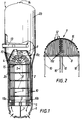
- Figure 1 is an elevational view in partial section through a vertical plane of a steam generator of a pressurized water nuclear reactor.
- FIG. 2 is a schematic sectional view of the upper part of the bun in a plane perpendicular to that of FIG. 1.
- FIG. 3A is a detailed sectional view of FIG. 1 showing the ends of the anti-vibration bars on a part of the bun with a schematic representation of the connection means in the case of a steam generator having an array of square pitch tubes.
- FIG. 3B is a view similar to the view in FIG. 3A, in the case of a steam generator having a bundle of tubes with triangular pitch.
- Figure 4 is a perspective view of a portion of the tube support device according to the invention showing the connecting means and the anti-flight device.
- FIG. 4A is a detailed view of a support pad for the connection means on a tube.
- Figure 5 is a perspective view of a detail of the tube support device.
- Figure 5A is a sectional view of a detail of the central comb.
- Figure 6 is a sectional view showing the anti-theft device.
- FIG. 1 we see a steam generator of a pressurized water nuclear reactor generally designated by the reference 1.
- the steam generator comprises an outer casing 2 representing a lower part 2a having the shape of a cylindrical shell in which the bundle of tubes 3 of the steam generator is disposed, inside a bundle casing 4.
- the part upper 2b of the envelope 2 of the steam generator 1 has a diameter greater than the diameter of the lower part 2a and contains means for separating and drying the steam produced in contact with the bundle 3.
- the lower end portion of the shell 2a of the casing 2 is integral with a tubular plate 5 of very thick which is crossed by openings in which the bundle tubes 3 are introduced and fixed by welding and crimping (mechanical or hydraulic for example).
- a hemispherical casing 6 delimiting the water box of the steam generator in two parts separated by a partition 7.
- Each of the two parts of the water box is connected by a tube to the primary circuit of the nuclear reactor in which the water circulates under cooling pressure of the reactor core.
- the bundle 3 consists of tubes 10 which are bent and have a U-shape.
- Each of the tubes 10 comprises two rectilinear branches 10a, 10b and a substantially semi-circular curved part 10c between the straight branches 10a and 10b.
- the ends of the branches 10a and 10b are engaged and crimped in openings passing through the tubular plate 5, on either side of the partition 7.
- the straight branches 10a, 10b of the tubes 10 of the bundle are also engaged in openings passing through spacer plates 8 arranged spaced apart according to the height of the bundle.
- the network of openings of each of the spacer plates reproduces the network of openings of the tubular plate 5, so that the branches 10a and 10b are maintained in parallel arrangements.
- the network of openings of the tubular plate 5 and of the spacer plates 8 comprises rectilinear rows in which the straight branches of tubes 10 are engaged, the curved part 10c of which has a decreasing radius of curvature from the outside towards the inside the beam.
- the bundle tubes thus constitute successive layers 12 which are visible in particular in FIG. 2.
- the radii of curvature of the curved parts 10c or tube hangers are decreasing from the outside to the inside, that is to say from top to bottom; in addition, the radius of curvature of the outer tube of the sheet having the maximum radius of curvature decreases from the inner central part towards the outside of the bundle.
- the bun 9 constituted by the hangers 10c juxtaposed with the tubes 10 has a substantially hemispherical shape.
- the networks of engagement openings of the tubes of the tube plate 5 and of the spacer plates 8 are interrupted at the central part of the plates in a diametrical direction, so as to delimit a free space or street of water 11 at the central part of the beam between the branches of the tubes having the smallest radii of curvature under the small hangers which are aligned in the diametrical direction of the water street 11.
- the steam generator 1 comprises a torus 13 disposed above the upper part of the bundle envelope 4 in which the bun 9 is placed.
- pressurized water for cooling the reactor enters one of the compartments of the water box so as to be distributed inside the branches 10a of the tubes 10 of the bundle opening into this entry compartment.
- the pressurized water circulates inside the tubes to exit into the second compartment of the water box through the second branches 10b of the tubes 10.
- the water recovered at the outlet of the tubes of the bundle is returned to the reactor vessel nuclear via a primary circuit pipe.
- the feed water introduced into the envelope of the steam generator 2 through the feed toroid 13 circulates from top to bottom in an annular space formed between the bundle envelope 4 and the outer casing 2 of the steam generator then enters the inside of the bundle casing 4 to come into contact with the tubes 10 above the upper face of the tube plate 5.
- the supply water circulates from bottom to top inside the bundle, in contact with the tubes and heats up then vaporizes by heat exchange with pressurized water circulating inside the tubes.
- the vapor formed in contact with the bundle tubes is sent to the upper part 2b of the steam generator to be dried and then discharged through the upper end 14 of the steam generator.
- the bundle tubes inside each of the flat plies of tubes 12 are placed so as to have a certain spacing and the plies are also arranged with respect to each other, with a certain spacing.
- the steam generator feed water can thus circulate in contact with the entire external surface of the tubes.
- the outer ends 15b of the branches of the anti-vibration bars project from the upper surface of the bun and allow the fixing of the anti-vibration bars.
- an anti-vibration bar will designate any branch of a V-shaped assembly 15.
- FIGS 3A and 3B there is shown in a sectional view of the plies of tubes in their upper part, part of a wedging assembly according to the invention, in the case of a bundle of tubes held in an arrangement with square mesh network and in the case of a bundle of tubes held in a triangular mesh network arrangement, respectively.
- the bundle tubes are held in a regular network arrangement by the openings of the tube plate 5 and by the through openings of the spacer plates 8 which comprise networks of similar openings.
- the arrangement of the tubes in the case of a triangular mesh network results in particular in a smaller space between the successive layers of tubes than in the case of a square mesh network.
- the device according to the invention applies as well in the case of a network of tight tubes with triangular meshes as in the case of a network with square meshes.
- FIGS. 3A and 3B show the tubes 10 or 10 ′ of the network of tubes constituting the external layers of the bun of the steam generator.
- the tubes 10 or 10 ′ constitute successive parallel plies between which the anti-vibration bars 15 or 15 ′ are interposed.
- the layers of tubes are formed by the upper bent portions of the juxtaposed tubes and with decreasing radii from the outside towards the inside of the bun.
- the anti-vibration bars 15 have ends 15b projecting outside the bun and arranged in alignment with one another to form alignments of variable length.
- the projecting ends 15b of the antivibration bars are connected together by connecting means 20 making it possible to ensure the connection of two or a greater number of antivibration bars constituting a set of aligned bars.
- connection means 20 ′ making it possible to link together the ends of a set of two or more anti-vibration bars.
- connection means 20 of a wedging device making it possible to connect the ends of the anti-vibration bars 15 to one another.
- Each of the connecting means 20 consists of an elongated piece 21 called a comb and comprising notches 21a, of a closing bar constituting the cover 22 intended to be positioned on the notches 21a, and means for fixing the cover to the comb constituted by one or more screws 23.
- the notches 21a are dimensioned so as to receive the ends of the anti-vibration bars 15.
- a comb 21 has at least two notches to allow the connection of the anti-vibration bars.
- the central comb which turns out to be the most important can comprise for example, up to thirty notches.
- preferential anti-vibration bars 15 are used which have notches in their end part.
- the notches of the antivibration bars 15 are positioned facing the notch of the comb so as to come to fit on the bottom of the notch of the comb, which ensures the effective maintenance of the end of the antivibration bar on the means of connection 20.
- the depth and the width of the notches of the comb are dimensioned so that the section of the anti-vibration bar 15 situated in the notch 21a of the comb comes approximately to fill said notch.
- the comb 21 has one or more tapped holes arranged between the notches on the face where the openings of the notches are located and intended to receive the connecting screws 23.
- the cover 22 has the form of an elongated bar and has one or more holes for the passage of the connecting screws 23.
- certain combs have complementary tapped holes arranged in the face where the openings of the notches are located and also in the end face of said combs, as will be explained below.
- stops 24 composed of a shoe 25, a jumper 26 and d 'A screw 27, are installed on the combs and come to bear on certain tubes 10 located towards the outside of the bun 9.
- the detailed drawing of the stop 24 is shown in Figure 4A.
- the shoe 25 has the shape of a small elongated plate, it has a rounded profile 25a recessed the size of the outside profile of a tube 10, this rounded profile represents the bearing surface on the tube; the width of said stop is slightly greater than the diameter of a tube except on a part where the stop has two recesses 25b; said abutment has an oblong hole between the two recesses, arranged lengthwise to allow adjustment of the position of the abutment during assembly.
- the rider 26 has a section in the shape of an inverted U, its length is substantially that of the recesses of the shoe 25, it is equipped with an oblong hole and is positioned on the shoe 25, at the level of the recesses.
- the screw 27 secures the shoe 25 and the rider 26 on the comb 21 by screwing into a threaded hole existing on the comb.
- a weld between the rider 26 and the comb 21 ensures the final positioning of the shoe 25.
- a weld point between the screw head 27 and the rider 26 ensures the inessibility of the screw 27.
- the connecting means 20 connecting the ends of the anti-vibration bars 15 located in the same meridian plane of the bun are all integral with one another by the fact that two successive connecting means 20 trap one end 15 b of the common anti-vibration bar 15 which is therefore located inserted into two successive combs 21.
- anti-vibration bars 15 connected to two successive connecting means then have two notches to be inserted into the notches of the two successive combs.
- arches 30 are arranged arranged in parallels of the hemispherical shape of the bun, arranged outside of the bun 9 and connecting together the various end connection assemblies .
- connection between the hoops 30 and the connecting means 20 is achieved by the fact that each hoop is connected to a comb 21 of each assembly for connecting the ends.
- the connection between a hoop 30 and a comb 21 is carried out by a screw 31 passing through the hoop 30 in which a hole has been arranged and which is screwed into the tapped hole located in the end face of the comb 21 and described above.
- arches 30 there will be seven arches 30 to hold all the ends of the anti-vibration bars in a rigid assembly.
- the different arches 30 have different radii depending on their location above the bun.
- the positioning of the bundle tubes and the anti-vibration bars can be carried out according to the method described in patent FR-A-2 603 364 from the company FRAMATOME.
- the tubes are mounted in successive layers from the largest layer located in the center according to the plane of FIG. 1 towards the layers of decreasing size and progressively inserting the anti-vibration bars, when half of the beam is mounted, the steam generator is rotated 180 ° along its axis then located in a horizontal position and the other half of the bundle is mounted, starting from the largest dimension of the layer towards the decreasing sizes of layers.
- central arch 30 In order to be able to install the central arch 30 and the central comb 21, there is a central comb composed of two half-combs, the longitudinal assembly of which is carried out by a dovetail type assembly as shown in FIG. 5A .
- Each half-comb is equipped with a support console 28 which is screwed with the cover 22 of the comb.
- the support brackets 28 are mounted with the covers of each half-comb and have a tapped hole to receive a fixing screw.
- the hoop is fitted with lugs 29 which are fixed by means of a fixing screw, passing through the lug and being screwed into the tapped hole of the support brackets 28.
- the assembly of the anti-vibration wedging device constituted by the anti-vibration bars 15, the end connection assemblies and the arches 30, is held by an anti-flight device.
- the previously described wedging device can move as a whole between the plies of tubes.
- the initial positioning of the device produced during assembly could be modified in particular during the operation of the steam generator.
- devices with anti-flight stirrups retained by the tubes or with a rail on the spacer plate located near the bun were used.
- supports 40 are used which are fixed to the bundle casing 4 and connected to the anti-vibration wedging device.
- the anti-take-off device which we will describe could be used with an anti-vibration wedging device different from that described above and in particular at the level of the connections of the ends of the anti-vibration bars.
- the support 40 intended to ensure the anti-takeoff function consists of a metal tab 41 rigidly fixed, by welding on the bundle envelope 4.
- the support tab 41 has at its end opposite to the bundle envelope 4, a hinge 42 intended to receive a dowel 44.
- the dowel 44 is arranged in a direction parallel to the axis of the steam generator.
- a lug 32 rigidly fixed by welding and integral with the arch.
- the tab 32 is substantially flat and disposed in a substantially horizontal position, below the hinge 42 and the support tab 41, which are located in the extension of one another with their lower faces located in the same horizontal plane 43.
- the tab 32 has an opening 33 of dimensions slightly larger than that of the section of the plug 44.
- the pin 44 longer than the length of the hinge 42 is introduced into the hinge 42 so as to protrude a few millimeters above the hinge 42, and several centimeters below the hinge 42 by crossing the opening of the tab 32. It is then welded, in the upper part, by a weld 45 on the upper face of the hinge 42 .
- the device thus constituted with the supports makes it possible to ensure that the whole of the anti-vibration wedging device will be well maintained in a position close to that established during assembly, and limits both the vertical movement of the anti-vibration device upwards. steam generator and its tilting.
- the opening 33 in the tab 32 is larger than the pin 44 and therefore allows limited movement of the support device in a horizontal plane.
- a washer 46 is positioned at the lower end of the dowel 44 and fixed to said dowel by a weld 47, this makes it possible to ensure that the tab 32 of the hoop 30 can in no way case come out of its threaded position on the ankle 44.
- the support device thus described is reproduced at the two ends of the arch 30.
- the device for fixing the ends of the anti-vibration bars could be produced according to a device already known and be associated with anti-theft supports such as that which has been described.
- the anti-take-off device could be produced in a different way, on the condition of allowing the production of a limited clearance for the movement of all of the connecting means.
- the anti-vibration bars may be of a different shape from that which has been described.
- the invention applies in the case of any steam generator or heat exchanger comprising a regular network of tubes comprising curved parts between which are inserted anti-vibration bars.
Landscapes
- Engineering & Computer Science (AREA)
- Physics & Mathematics (AREA)
- Thermal Sciences (AREA)
- Mechanical Engineering (AREA)
- General Engineering & Computer Science (AREA)
- Heat-Exchange Devices With Radiators And Conduit Assemblies (AREA)
Priority Applications (1)
| Application Number | Priority Date | Filing Date | Title |
|---|---|---|---|
| EP00121012A EP1061320A3 (de) | 1995-03-09 | 1996-03-05 | Wärmetauscher mit U-Röhren, mit einer Anti-Auftrieb- und schwingungsneutralisierender Rohrhalterungsvorrichtung |
Applications Claiming Priority (2)
| Application Number | Priority Date | Filing Date | Title |
|---|---|---|---|
| FR9502745A FR2731508B1 (fr) | 1995-03-09 | 1995-03-09 | Echangeur de chaleur, a tubes en u, equipe d'un dispositif de calage des tubes, antivibratoire et anti-envol |
| FR9502745 | 1995-03-09 |
Related Child Applications (1)
| Application Number | Title | Priority Date | Filing Date |
|---|---|---|---|
| EP00121012A Division EP1061320A3 (de) | 1995-03-09 | 1996-03-05 | Wärmetauscher mit U-Röhren, mit einer Anti-Auftrieb- und schwingungsneutralisierender Rohrhalterungsvorrichtung |
Publications (2)
| Publication Number | Publication Date |
|---|---|
| EP0731328A1 true EP0731328A1 (de) | 1996-09-11 |
| EP0731328B1 EP0731328B1 (de) | 2001-04-25 |
Family
ID=9476892
Family Applications (2)
| Application Number | Title | Priority Date | Filing Date |
|---|---|---|---|
| EP96400463A Expired - Lifetime EP0731328B1 (de) | 1995-03-09 | 1996-03-05 | Wärmetauscher mit U-Röhren, mit einer Anti-Auftrieb- und schwingungsneutralisierender Rohrhalterungsvorrichtung |
| EP00121012A Withdrawn EP1061320A3 (de) | 1995-03-09 | 1996-03-05 | Wärmetauscher mit U-Röhren, mit einer Anti-Auftrieb- und schwingungsneutralisierender Rohrhalterungsvorrichtung |
Family Applications After (1)
| Application Number | Title | Priority Date | Filing Date |
|---|---|---|---|
| EP00121012A Withdrawn EP1061320A3 (de) | 1995-03-09 | 1996-03-05 | Wärmetauscher mit U-Röhren, mit einer Anti-Auftrieb- und schwingungsneutralisierender Rohrhalterungsvorrichtung |
Country Status (8)
| Country | Link |
|---|---|
| US (1) | US5692557A (de) |
| EP (2) | EP0731328B1 (de) |
| JP (2) | JP3773980B2 (de) |
| KR (1) | KR100397689B1 (de) |
| CN (1) | CN1099020C (de) |
| DE (1) | DE69612581T2 (de) |
| FR (1) | FR2731508B1 (de) |
| TW (1) | TW307876B (de) |
Cited By (2)
| Publication number | Priority date | Publication date | Assignee | Title |
|---|---|---|---|---|
| WO2014011516A3 (en) * | 2012-07-13 | 2014-03-13 | Areva Np Inc. | U-bend tube compression/distortion stabilization system (cdss) |
| WO2015007851A1 (fr) * | 2013-07-19 | 2015-01-22 | Areva Np | Barre antivibratoire pour faisceau de tubes d'un generateur de vapeur |
Families Citing this family (28)
| Publication number | Priority date | Publication date | Assignee | Title |
|---|---|---|---|---|
| US7793708B2 (en) * | 2004-06-18 | 2010-09-14 | Exxonmobil Research & Engineering Company | Anti-vibration tube support |
| JP4585414B2 (ja) * | 2005-09-16 | 2010-11-24 | 三菱重工業株式会社 | 振動防止装置およびこれを用いた熱交換器 |
| KR100728892B1 (ko) * | 2005-12-20 | 2007-06-14 | 주식회사 실트론 | 에피택셜 반응기의 서셉터 |
| US8695688B2 (en) * | 2007-07-18 | 2014-04-15 | Babcock & Wilcox Canada Ltd. | Nubbed U-bend tube support |
| JP5167008B2 (ja) * | 2008-07-22 | 2013-03-21 | エスペック株式会社 | 結露量の制御可能な環境試験装置およびその結露量制御方法 |
| US20100116478A1 (en) * | 2008-11-12 | 2010-05-13 | Exxonmobil Research And Engineering Company | Displaceable baffle for a heat exchanger and method for reducing vibration for the same |
| JP5582004B2 (ja) * | 2010-12-07 | 2014-09-03 | 株式会社Ihi | 伝熱管振れ防止バーの固定方法 |
| US9697919B2 (en) * | 2010-12-29 | 2017-07-04 | Westinghouse Electric Company, Llc | Anti-vibration tube support plate arrangement for steam generators |
| EP2522943A1 (de) | 2011-05-11 | 2012-11-14 | Borgwarner Emission Systems Spain, S.L. | Vorrichtung zur Verringerung der Vibrationen eines Rohrkerns eines Wärmetausches in seinem Gehäuse |
| JP5901266B2 (ja) * | 2011-12-12 | 2016-04-06 | 三菱重工業株式会社 | 蒸気発生器 |
| JP5885949B2 (ja) * | 2011-06-28 | 2016-03-16 | 三菱重工業株式会社 | 蒸気発生器 |
| JP5901244B2 (ja) * | 2011-11-18 | 2016-04-06 | 三菱重工業株式会社 | 蒸気発生器 |
| US20140014295A1 (en) * | 2011-06-28 | 2014-01-16 | Mitsubishi Heavy Industries, Ltd. | Steam generator |
| CN102393159B (zh) * | 2011-09-16 | 2013-09-11 | 茂名重力石化机械制造有限公司 | 一种具有u形管束防振装置的管壳式换热器 |
| US20140116360A1 (en) * | 2012-10-31 | 2014-05-01 | Westinghouse Electric Company Llc | Method and apparatus for securing tubes in a steam generator against vibration |
| CN103871488A (zh) * | 2012-12-13 | 2014-06-18 | 中国核动力研究设计院 | 一种用于压水堆核电厂蒸汽发生器的防振条结构 |
| CN103317245B (zh) * | 2013-06-05 | 2015-08-19 | 上海电气核电设备有限公司 | 一种核电蒸汽发生器穿管和抗震条装焊的方法 |
| WO2015007375A1 (de) * | 2013-07-16 | 2015-01-22 | Linde Aktiengesellschaft | Wärmeübertrager mit elastischem element |
| RU2570964C1 (ru) * | 2014-12-12 | 2015-12-20 | Открытое акционерное общество "Ордена Трудового Красного Знамени и ордена труда ЧССР опытное конструкторское бюро "ГИДРОПРЕСС" (ОАО ОКБ "ГИДРОПРЕСС") | Коллектор теплоносителя парогенератора с u-образными трубами горизонтального теплообменного пучка и способ его изготовления |
| FR3032031B1 (fr) * | 2015-01-26 | 2017-01-27 | Valeo Systemes Thermiques | Batterie thermique a materiau a changement de phase encapsule. |
| CN105444606B (zh) * | 2015-12-29 | 2018-10-19 | 福建龙净环保股份有限公司 | 防磨假管组件、可拆卸安装件及烟气换热器 |
| CN106765024B (zh) * | 2016-11-24 | 2019-09-13 | 中广核工程有限公司 | 核电厂蒸汽发生器防振条结构 |
| CN106989380A (zh) * | 2017-05-05 | 2017-07-28 | 哈电集团(秦皇岛)重型装备有限公司 | 高温气冷堆蒸汽发生器蒸汽出口连接管弯头结构 |
| US12183472B2 (en) * | 2018-06-18 | 2024-12-31 | Ge-Hitachi Nuclear Energy Americas Llc | Systems and methods for steam separator tie bar repair or replacement |
| CN108954288B (zh) * | 2018-07-11 | 2020-01-07 | 东方电气(广州)重型机器有限公司 | 一种管束抗震条阻尼装置及限位方法 |
| CN109541024B (zh) * | 2018-11-09 | 2025-01-10 | 上海金艺检测技术有限公司 | 换热器管束管壁腐蚀状况超声检测支架及使用方法 |
| CN109654913B (zh) * | 2018-12-06 | 2020-05-01 | 中广核工程有限公司 | 核电站换热器弯管折流结构 |
| CN117549250A (zh) * | 2023-11-28 | 2024-02-13 | 哈电集团(秦皇岛)重型装备有限公司 | 一种热交换器斜向排列管束支撑条撑胀装置及穿管方法 |
Citations (3)
| Publication number | Priority date | Publication date | Assignee | Title |
|---|---|---|---|---|
| FR2648945A1 (fr) * | 1989-06-27 | 1990-12-28 | Framatome Sa | Dispositif de liaison de l'extremite exterieure d'une barre antivibratoire d'un generateur de vapeur |
| EP0633427A1 (de) * | 1993-07-09 | 1995-01-11 | Framatome | Wärmetauscher mit U-Rohrbündel und schwingungsneutralisierenden Stangen zwischen dem gekrümmten Teil |
| EP0639741A1 (de) * | 1993-08-20 | 1995-02-22 | Framatome | Wärmetauscher mit Haltevorrichtung für zwischen die Rohre eingelegte Dämpfungsstangen |
Family Cites Families (9)
| Publication number | Priority date | Publication date | Assignee | Title |
|---|---|---|---|---|
| US3199582A (en) * | 1962-04-06 | 1965-08-10 | Foster Wheeler Corp | Heat exchanger tube anti-vibration structure |
| US3212567A (en) * | 1962-05-08 | 1965-10-19 | Combustion Eng | Anti-vibration support means |
| US4202085A (en) * | 1978-11-30 | 1980-05-13 | Westinghouse Electric Corp. | Apparatus and method for installing rows of U-shaped tubes in a heat exchanger |
| US4319725A (en) * | 1980-03-21 | 1982-03-16 | Westinghouse Electric Corp. | Apparatus for vertically tubing a heat exchanger |
| US5005637A (en) * | 1986-11-05 | 1991-04-09 | Phillips Petroleum Company | Heat exchanger U-bend tube support |
| US4895204A (en) * | 1987-12-24 | 1990-01-23 | Foster Wheeler Energy Corporation | Tube support vibration suppression device and method |
| FR2644281B1 (fr) * | 1989-03-09 | 1991-06-07 | Framatome Sa | Dispositif de stabilisation des tubes du faisceau d'un generateur de vapeur comportant des barres antivibratoires |
| FR2664965B1 (fr) * | 1990-07-20 | 1992-11-06 | Framatome Sa | Dispositif de calage antivibratoire de tubes d'un echangeur de chaleur. |
| FR2711419B1 (fr) * | 1993-10-20 | 1996-02-02 | Framatome Sa | Dispositif de calage antivibratoire de tubes d'un échangeur de chaleur et utilisation. |
-
1995
- 1995-03-09 FR FR9502745A patent/FR2731508B1/fr not_active Expired - Lifetime
-
1996
- 1996-03-05 US US08/611,132 patent/US5692557A/en not_active Expired - Lifetime
- 1996-03-05 EP EP96400463A patent/EP0731328B1/de not_active Expired - Lifetime
- 1996-03-05 DE DE69612581T patent/DE69612581T2/de not_active Expired - Lifetime
- 1996-03-05 EP EP00121012A patent/EP1061320A3/de not_active Withdrawn
- 1996-03-05 TW TW085102702A patent/TW307876B/zh not_active IP Right Cessation
- 1996-03-08 KR KR1019960006685A patent/KR100397689B1/ko not_active Expired - Lifetime
- 1996-03-09 CN CN96106061A patent/CN1099020C/zh not_active Expired - Lifetime
- 1996-03-11 JP JP05345796A patent/JP3773980B2/ja not_active Expired - Fee Related
-
2005
- 2005-11-25 JP JP2005340644A patent/JP3923991B2/ja not_active Expired - Lifetime
Patent Citations (3)
| Publication number | Priority date | Publication date | Assignee | Title |
|---|---|---|---|---|
| FR2648945A1 (fr) * | 1989-06-27 | 1990-12-28 | Framatome Sa | Dispositif de liaison de l'extremite exterieure d'une barre antivibratoire d'un generateur de vapeur |
| EP0633427A1 (de) * | 1993-07-09 | 1995-01-11 | Framatome | Wärmetauscher mit U-Rohrbündel und schwingungsneutralisierenden Stangen zwischen dem gekrümmten Teil |
| EP0639741A1 (de) * | 1993-08-20 | 1995-02-22 | Framatome | Wärmetauscher mit Haltevorrichtung für zwischen die Rohre eingelegte Dämpfungsstangen |
Cited By (3)
| Publication number | Priority date | Publication date | Assignee | Title |
|---|---|---|---|---|
| WO2014011516A3 (en) * | 2012-07-13 | 2014-03-13 | Areva Np Inc. | U-bend tube compression/distortion stabilization system (cdss) |
| WO2015007851A1 (fr) * | 2013-07-19 | 2015-01-22 | Areva Np | Barre antivibratoire pour faisceau de tubes d'un generateur de vapeur |
| FR3008779A1 (fr) * | 2013-07-19 | 2015-01-23 | Areva Np | Barre antivibratoire pour faisceau de tubes d'un generateur de vapeur |
Also Published As
| Publication number | Publication date |
|---|---|
| JP3923991B2 (ja) | 2007-06-06 |
| FR2731508A1 (fr) | 1996-09-13 |
| CN1099020C (zh) | 2003-01-15 |
| KR100397689B1 (ko) | 2003-12-31 |
| KR960034964A (ko) | 1996-10-24 |
| CN1160183A (zh) | 1997-09-24 |
| FR2731508B1 (fr) | 1997-05-09 |
| DE69612581T2 (de) | 2001-09-06 |
| EP0731328B1 (de) | 2001-04-25 |
| JPH08261404A (ja) | 1996-10-11 |
| DE69612581D1 (de) | 2001-05-31 |
| EP1061320A2 (de) | 2000-12-20 |
| US5692557A (en) | 1997-12-02 |
| TW307876B (de) | 1997-06-11 |
| JP3773980B2 (ja) | 2006-05-10 |
| JP2006105589A (ja) | 2006-04-20 |
| EP1061320A3 (de) | 2001-01-17 |
Similar Documents
| Publication | Publication Date | Title |
|---|---|---|
| EP0731328B1 (de) | Wärmetauscher mit U-Röhren, mit einer Anti-Auftrieb- und schwingungsneutralisierender Rohrhalterungsvorrichtung | |
| FR2707382A1 (fr) | Echangeur de chaleur comportant un faisceau de tubes cintrés en U et des barres antivibratoires entre les parties cintrées des tubes. | |
| EP0639741B1 (de) | Wärmetauscher mit Haltevorrichtung für zwischen die Rohre eingelegte Dämpfungsstangen | |
| EP0387131B1 (de) | Vorrichtung zur Stabilisierung von Rohren eines Dampferzeugerrohrbündels mit schwingungsneutralisierenden Stangen | |
| FR2581471A1 (fr) | Structure expansible de support de tubes avec barres antivibrations pour generateur de vapeur de centrale nucleaire | |
| EP0117168B1 (de) | Halterungsanordnung für den Core eines Druckwasser-Kernreaktors | |
| EP0178985B1 (de) | Fluidumerhitzungsapparat | |
| EP0654636A1 (de) | Vorrichtung für schwingungsneutralisierendes Festsetzen von Wärmetauscherrohren und seine Verwendung | |
| EP0288361B1 (de) | Vorrichtung zum schwingungsneutralisierenden Festsetzen von Dampferzeugerrohren und schwingungsneutralisierende Stangen dafür | |
| EP0648974B1 (de) | Dampferzeuger mit radialer Haltevorrichtung für die Rohrbündelhülle und die Rohrabstandsplatten | |
| EP0078728B1 (de) | Schwingungsdämpfende Halterung für ein Rohrbündel, insbesondere für einen Dampferzeuger, und Verfahren zum Montieren dieser Halterung | |
| EP0012042B1 (de) | Anordnung zur Halterung und Abschirmung nuklearer Dampf-Generatoren | |
| EP0544579B1 (de) | Wärmetauscher mit U-Rohren und Anti-Auftriebshalterung | |
| FR2707373A1 (fr) | Dispositif de maintien radial de l'enveloppe de faisceau et des plaques-entretoises d'un générateur de vapeur. | |
| FR2731329A1 (fr) | Canape lit baignoire | |
| FR2707733A1 (fr) | Générateur de vapeur à cyclones démontables. | |
| EP0173602A1 (de) | Notwärmetauscher zur Kühlung des Primärmittels eines Kernreaktors und Verfahren zu dessen Zusammenbau | |
| EP0197812B1 (de) | Wärmetauscher mit schraubenförmigen Rohren mit Haltevorrichtungen | |
| FR2858845A1 (fr) | Echangeur de chaleur et procede de fabrication | |
| BE1007153A5 (fr) | Echangeur de chaleur a dispositif de maintien anti-sismique et de supportage anti-envol de l'enveloppe entourant le faisceau de tubes. | |
| FR2707372A1 (fr) | Dispositif de maintien radial de l'enveloppe de faisceau et des plaques-entretoises d'un générateur de vapeur par des butées à excentrique. | |
| EP1998110A2 (de) | Vorrichtung und Verfahren zum Abdichten einer Öffnung in der Strahlenhülle eines Dampfgenerators eines Druckwasserkernreaktors | |
| EP0048672A1 (de) | Atomkernreaktor mit Wärmetauschern in integrierter Bauweise | |
| EP0086695A1 (de) | Dampferzeuger mit U-Rohrbündel und Überhitzer | |
| FR2712960A1 (fr) | Dispositif de maintien radial de l'enveloppe de faisceau et des plaques-entretoises d'un générateur de vapeur par des butées à vis prisonnière. |
Legal Events
| Date | Code | Title | Description |
|---|---|---|---|
| PUAI | Public reference made under article 153(3) epc to a published international application that has entered the european phase |
Free format text: ORIGINAL CODE: 0009012 |
|
| AK | Designated contracting states |
Kind code of ref document: A1 Designated state(s): BE DE GB SE |
|
| 17P | Request for examination filed |
Effective date: 19970210 |
|
| 17Q | First examination report despatched |
Effective date: 19990312 |
|
| GRAG | Despatch of communication of intention to grant |
Free format text: ORIGINAL CODE: EPIDOS AGRA |
|
| GRAG | Despatch of communication of intention to grant |
Free format text: ORIGINAL CODE: EPIDOS AGRA |
|
| GRAH | Despatch of communication of intention to grant a patent |
Free format text: ORIGINAL CODE: EPIDOS IGRA |
|
| GRAH | Despatch of communication of intention to grant a patent |
Free format text: ORIGINAL CODE: EPIDOS IGRA |
|
| RAP1 | Party data changed (applicant data changed or rights of an application transferred) |
Owner name: FRAMATOME |
|
| GRAA | (expected) grant |
Free format text: ORIGINAL CODE: 0009210 |
|
| AK | Designated contracting states |
Kind code of ref document: B1 Designated state(s): BE DE GB SE |
|
| RAP2 | Party data changed (patent owner data changed or rights of a patent transferred) |
Owner name: FRAMATOME ANP |
|
| REF | Corresponds to: |
Ref document number: 69612581 Country of ref document: DE Date of ref document: 20010531 |
|
| GBT | Gb: translation of ep patent filed (gb section 77(6)(a)/1977) |
Effective date: 20010518 |
|
| REG | Reference to a national code |
Ref country code: GB Ref legal event code: IF02 |
|
| PLBE | No opposition filed within time limit |
Free format text: ORIGINAL CODE: 0009261 |
|
| STAA | Information on the status of an ep patent application or granted ep patent |
Free format text: STATUS: NO OPPOSITION FILED WITHIN TIME LIMIT |
|
| 26N | No opposition filed | ||
| PGFP | Annual fee paid to national office [announced via postgrant information from national office to epo] |
Ref country code: DE Payment date: 20120328 Year of fee payment: 17 |
|
| REG | Reference to a national code |
Ref country code: DE Ref legal event code: R119 Ref document number: 69612581 Country of ref document: DE Effective date: 20131001 |
|
| PG25 | Lapsed in a contracting state [announced via postgrant information from national office to epo] |
Ref country code: DE Free format text: LAPSE BECAUSE OF NON-PAYMENT OF DUE FEES Effective date: 20131001 |
|
| PGFP | Annual fee paid to national office [announced via postgrant information from national office to epo] |
Ref country code: GB Payment date: 20150316 Year of fee payment: 20 Ref country code: SE Payment date: 20150311 Year of fee payment: 20 |
|
| PGFP | Annual fee paid to national office [announced via postgrant information from national office to epo] |
Ref country code: BE Payment date: 20150330 Year of fee payment: 20 |
|
| REG | Reference to a national code |
Ref country code: GB Ref legal event code: PE20 Expiry date: 20160304 |
|
| PG25 | Lapsed in a contracting state [announced via postgrant information from national office to epo] |
Ref country code: GB Free format text: LAPSE BECAUSE OF EXPIRATION OF PROTECTION Effective date: 20160304 |
|
| REG | Reference to a national code |
Ref country code: SE Ref legal event code: EUG |