EP0732257A1 - Gummi-raupenband mit verbindungsglied - Google Patents
Gummi-raupenband mit verbindungsglied Download PDFInfo
- Publication number
- EP0732257A1 EP0732257A1 EP94903084A EP94903084A EP0732257A1 EP 0732257 A1 EP0732257 A1 EP 0732257A1 EP 94903084 A EP94903084 A EP 94903084A EP 94903084 A EP94903084 A EP 94903084A EP 0732257 A1 EP0732257 A1 EP 0732257A1
- Authority
- EP
- European Patent Office
- Prior art keywords
- rubber crawler
- crawler
- rubber
- core bar
- track
- Prior art date
- Legal status (The legal status is an assumption and is not a legal conclusion. Google has not performed a legal analysis and makes no representation as to the accuracy of the status listed.)
- Granted
Links
Images


Classifications
-
- B—PERFORMING OPERATIONS; TRANSPORTING
- B62—LAND VEHICLES FOR TRAVELLING OTHERWISE THAN ON RAILS
- B62D—MOTOR VEHICLES; TRAILERS
- B62D55/00—Endless track vehicles
- B62D55/08—Endless track units; Parts thereof
- B62D55/18—Tracks
- B62D55/24—Tracks of continuously flexible type, e.g. rubber belts
- B62D55/244—Moulded in one piece, with either smooth surfaces or surfaces having projections, e.g. incorporating reinforcing elements
Definitions
- the present invention relates to a connecting link type rubber crawler suitably mounted to a traveling unit of a mobile construction machine, etc.
- a steel crawler has been mainly applied to the traveling unit of a mobile construction machine, and a rubber shoe has been partially applied thereto. Recently, however, a rubber crawler is preferably used.
- Fig. 22 is an explanatory view to describe an example of a conventional steel crawler: 101 is an outer flanged rolling wheel, 102 is a crawler shoe. 102a is a shoe plate, 102b is a track link, 102c is a linkage pin, and 102d is a lug (steel made).
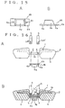
- Fig. 23 is an explanatory view to describe an example of a rubber shoe: 103 is a rubber shoe, 103a is a shoe plate, 103b is a track link, 103c is a linkage pin, 103d is a rubber lug.
- Fig. 22 is an explanatory view to describe an example of a conventional steel crawler: 101 is an outer flanged rolling wheel, 102 is a crawler shoe. 102a is a shoe plate, 102b is a track link, 102c is a linkage pin, and 102d is a lug (steel made).
- Fig. 23 is an explanatory view to describe
- 104 is a rubber crawler
- 104c is a lug
- 105 is a core metal
- 106 is a steel cord.
- Figs. 22 ⁇ 24 the same outer flanged rolling wheel can be used.
- a steel crawler wherein the upper surface of track links serves as a continuous track for a rolling wheel, effects small vibrations during traveling. Besides, it scarcely deviates from the wheel because of no elongation nor side displacement of the crawler in a circumferntial or width direction. Moreover, it is excellent in durability because of strong mechanical connection between the links. However, it causes big noise and gives heavy fatigue to a driver because of its poor cushioning ability. In addition, it damages roads.
- a rubber crawler effects small noise and has good cushioning ability without damaging roads. Besides, it is relatively lightweight so as to drive at high speed. However, it causes somewhat strong driving vibrations because an upper face of a projection of each core metal serves as a wheel track. In addition, when it receives big outer pressure in its circumferential or width direction, which causes elongation and side displacement, it deviates from the wheel. Moreover, it is inferior to the steel crawler in mechanical strength and durability.
- a rubber shoe wherein a rubber lug is provided on the ground side of a shoe plate of a steel crawler, has such structural problems that the shoe plat is apt to come off the rubber lug, and that the rubber lug is easily damaged or worn down because it is pressed between the shoe plate and the ground without any space for escape. Besides, a method of vulcanizing and fixing a rubber lug to each shoe plate highers the cost considerably. Accordingly, it can not be superior to a rubber crawler.
- an object of the present invention is to overcome the above demerits of the rubber crawler by adapting a structure of a steel crawler with its merits.
- This invention is characterized by a connecting link type rubber crawler, being endless or in a belt form, wherein core bars are embedded at suitable intervals with their longitudinal direction perpendicular to the circumferential direction of the crawler body; wherein the core bar comprises a center part and right and left wing portions, said center part having connecting portions (m), (m) on both sides thereof for fixing track links; wherein the right and left wing portions are embedded in a rubber material of the crawler body; wherein the connecting parts (m), (m) are exposed at least on the inner peripheral side of the crawler body or covered by a thin rubber layer; wherein the track link is provided with pin holes on both sides thereof and connecting portions (m'), (m') on lower surface thereof between the pin holes; wherein an interval between the pin holes coincides with a center-to-center interval between the adjoining core bars; wherein the connecting portions (m), (m') of the core bar and the track link, respectively, are united so as to fix the track link on the core bar from the inner circum
- the track links are connected in a full circle on the inner circumferential side of the rubber crawler, thereby increasing mechanical strength in the circumferential direction of the crawler with no elongation nor slides.
- a wheel track is continuous in the full circule, thereby effecting no sinking of the wheel and decreasing running vibrations.
- the center part of the core bar may be concave relative to its right and left wing portion.
- the track link can be fixed at a relatively lower position relative to the rubber crawler body (near the outer circumferential side of the rubber crawler body), so that elongations on the outer circumferential side tend to be decreased, even when the rubber crawler body is curved and deformed by a driving wheel.
- one or a plurality of the rubber crawler shoes can be disposed between belting rubber crawler bodies with the respective ends facing with each other, said rubber crawler shoe having core bars and a reinforcing layer embedded therein.
- the rubber crawler bodies and the rubber crawler shoes can be connected with each other by means of track links fixed on the inner circumferential side thereof,
- This structure enables easy operations of fixing and removing to the crawler device, connection and extention of the crawler bodies in any length, and partial exchange of the body, etc.
- the second invention is characterized by a rubber crawler, wherein the length of a rubber crawler shoe in its circumferential direction (including an embedded core bar) almost coincides with an interval between pin holes on both sides of a track link; wherein reinforcing layers are provided above or/and under wing portions of an embedded core bar in the rubber crawler shoe; and wherein only the rubber crawler shoes are connected so as to form an endless body.
- This structure has the same effects as shown in claims 1, 2 and 4.
- the upper face of the rubber crawler shoe should be curved.
- an opening between the adjoining rubber crawler shoes can be small, when they are in contact with a circular arc of a driving wheel. Besides, it seems as if the height of the lug is increased, which can decrease running slides of the rubber crawler shoes on the ground.
- reinforcing layers should be provided above or/and under the right and left wing portions of the core bar so as to increase the strength of the rubber crawler shoe in the circumferential direction (claim 9).
- the third invention is characterized by a rubber crawler, wherein the length of a rubber crawler shoe in the circumferential direction (including an embedded core bar) almost coincides with an interval between pin holes on both sides of a track link; wherein a core bar having wing portions whose width is slightly shorter than the longitudinal length of the rubber crawler shoe is embedded therein, wherein the upper face of the rubber crawler shoe is curved, and wherein only the rubber crawler shoes are connected so as to form an endless body.
- This structure has also the same effects as shown in claims 1, 3 and 4.
- the center part of the core bar should be concave relative to its right and left wing portions, as shown in claim 2.
- the following central lug pad can increase availability of the invention.
- a central lug pad can be fixed to the center part of the core bar on its ground side (claim 10).
- This structure extends the touching area with the ground and enables easy operations of running the device, thereby increasing working working efficiency and safty.
- the central lug pad should be removable. Whit this structure, the central lug pad can be exchanged when damaged.
- the central lug pad is made of highly rigid and strong elastic body such as urethan rubber (claim 13). According to this, durablity of the central lug pad is excellently increased. Besides, urethan rubber has spike effects under the snowy roads, since its hardness extreamly increases at a low temperature.
- the hardness of the central lug pad is 75° ⁇ 95°, while that of the lug on the wing portions is 55° ⁇ 85° so as to bring about efficient running.
- FIGURE 1 relates to an embodiment of a core bar for a rubber crawler according to this invention: Fig. 1A is a perspective view, Fig. 1B is a side view, and Fig. 1C is a top view.
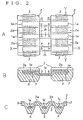
- FIGURE 2 shows a rubber crawler body wherein core bars shown in Fig. 1 are embedded at fixed intervals:
- Fig. 2A is a plan view
- Figs. 2B and 2C are sectional views in the lines X-X and Y-Y, respectively, of Fig. 2A.
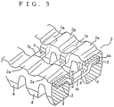
- FIGURE 3 shows a perspective view of the rubber crawler body shown in Fig. 2.
- FIGURE 4 shows a piece of track link of this invention: Fig. 4A is a front view and Fig. 4B is a bottom view.
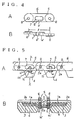
- FIGURE 5 is a partial view of the rubber crawler body in Fig. 2 having the track links in Fig. 4 fixed there to:
- Figs. 5A and 5B are sectional views in circumferential and width directions, respectively, of the rubber crawler.
- FIGURE 6 is an explanatory view to describe an engaging condition of a connecting link type rubber crawler of this invention to a driving or guiding wheel.
- FIGURE 7 shows an overlapping part of the rubber crawler of this invention: Fig. 7A is a plan view (on the inner circumferential side), Fig. 7B is a front view, and Fig. 7C is a sectional view in the line Y-Y of Fig. 7A.
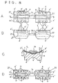
- FIGURE 8 relates to an embodiment of a connecting body (rubber crawler shoe) of this invention:
- Fig. 8A is a plan view (on the inner circumferential side)
- Fig. 8B is a front view
- Fig. 8C is a sectional view in the line Y-Y of Fig. 8A
- Fig. 8D is a plan view (on the ground side).
- FIGURE 9 shows a connected condition of the rubber crawler body of Fig. 7 and the rubber crawler shoe of Fig. 8:
- Fig. 9A is a plan view (on the inner circumferential side) and
- Fig. 9B is a sectional view in the line Y-Y of Fig. 9A.
- FIGURE 10 relates to a different embodiment of the rubber crawler shoe of this invention:
- Fig. 10A is a plan view (on the inner circumferential side)
- Fig. 10B is a front view
- Fig. 10C is a sectional view in the line Y-Y of Fig. 10A
- Fig. 10D is a sectional view to describe a connected condition.
- FIGURE 11 relates to a further different embodiment of the rubber crawler shoe of this invention:
- Fig. 11A is plan view (on the inner circumfrerential side)
- Fig. 11B is a sectional vew in the line Y-Y of Fig. 11A
- Fig. 11C is a sectional view to describe a connected condition.
- FIGURE 12 shows an example of a core bar used in a different embodiment of this invention: Fig. 12A is a top view, Fig. 12B is a side view, and Fig. 12C is a perspective view.
- FIGURE 13 shows a rubber crawler body having the core bars embedded at fixed intervals: Fig. 13A is a plan view (on the ground side), and Fig. 13B is a sectional view in the line X-X of Fig. 13A.
- FIGURE 14 shows a piece of track link used in this embodiment: Fig. 14A is a front view, and Fig. 14B is a bottom view.
- FIGURE 15 shows an embodiment of a central lug pad of this invention: Fig. 15A is a front view, and Fig. 15B a sectional view.
- FIGURE 16 is an explanatory view to describe processes of fixing the track links and the central lug pad to the rubber crawler body: Fig. 16A is a side view showing each arrangement, and Fig. 16B is a sectional view showing a fixed condition.
- FIGURE 17 is a plan view, showing the rubber crawler body having the central lug pads fixed thereto on the ground side.
- FIGURE 18 shows a different embodiment of a core bar: Fig. 18A is a top view, Fig. 18B is a bottom view, and Figs. 18C and 18D are sectional views in the lines X-X and Y-Y, respectively, of Fig. 18A.
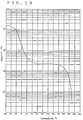
- FIGURE 19 is a graph showing a relationship between hardness and temperature of urethan rubber, wherein tile vertical axis shows modullus of a logarithm (tensile strength for 85% elongation (unit(PSI)) and the horizontal axis shows temperature (°C).
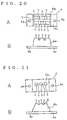
- FIGURE 20 shows a lug pattern of a central lug pad made of urethan rubber: Fig. 20A is a bottom view, and Fig. 20B is a side view.
- FIGURE 21 shows a different lug pattern of the central lug pad made of urethan rubber: Fig. 21A is a bottom view, and Fig. 21B is a sectional view.
- FIGURE 22 is an explanatory view to describe a conventional steel crawler.
- FIGURE 23 is an explanatory view to describe a conventional rubber shoe.
- FIGURE 24 is an explanatory view to describe a conventional rubber crawler.
- Fig. 1 shows an embodiment of a core bar used for a rubber crawler of this invention: Fig. 1A is a perspective view, Fig. 1B is a side view, and Fig. 1C is a top view.
- reference number 1 is a core bar
- 1a and 1a are right and left wing portions
- 1b is a concave center part
- m and m are connecting parts on both sides of the center part 1b for fixing later-described trak links
- p and p are bolt holes (through holes) provided on the connecting portions m, m, h shows a difference in height, said center part 1b being lower than the wing portions 1a.
- Fig. 2 shows a rubber crawler body 2 having the above core bars 1 embedded therein at fixed intervals:
- Fig. 2A is a plan view
- Figs. 2B and 2C are sectional views in the lines X-X and Y-Y, respectively, of Fig. 2A.
- the right and left wing portions 1a, 1a are embedded in a rubber material of the rubber crawler body 2, while the bolt holes p, p and their vicinities on the center part 1b are not embedded.
- Reference number 2a is a curvature which is so curved that the crawler body between two wing portions 1a and 1a adjacent in a circumferential direction is raised on the inner circumferential side.
- a reinforcing layer 3 is corrugate, since it is embedded under the wing portions 1a, as shown in Fig. 2C.
- a lug 4 projects on the outer circumferential side, corresponding to each wing portion 1a.
- Fig. 3 is a perspective view of the above rubber crawler body 2.
- Fig. 4 shows a piece of track link 5 used in this embodiment: Fig. 4A is a front view, and Fig. 4B is a bottom view. It is the same track link as has been conventionally used for some steel crawlers.
- reference numbers 6, 6 are right and left pin holes, and an interval l between the pin holes coinsides with an interval between core bars.
- Reference number 7 is a window
- 8 is a lower frame of the window
- m' is a connecting part on the lower face of the track link for being connected to the connecting part m of the core bar 1.
- a bolt hole p' on the connecting part m' goes through the lower frame 8, as shown in FIG. 4A.
- An upper face g of the track link 5 is plane, serving as a track for a wheel.
- the vicinities of the right and left pin holes 6, 6 are made thin (half of thickness t) oppositly on the right and left sides, so that the adjoining track links can be connected with each other in the same thickness.
- Fig. 5 is a partial view of the crawler body 2 of this embodiment having the track links fixed thereto:
- Figs. 5A and 5B are sectional views in the circumferential and width drections, respectively.
- the above bolt hole p' and the bolt hole p of the center part 1a of the core bar are united and bolted together, so that a pair of track links 5 are installed on both sides of the center part 1a.
- Each pin hole 6 of the adjacent track links is overlapped with each other, and a link pin is turnably inserted into the overlapped pin hole so as to connect the track links and form a continuos wheel track.
- Reference marks k and k' are a bolt and a nat, respectively, for connecting the track link 5 with the core bar 1, and in Fig. 5, 9 is a link pin.
- FIG. 6 is to explain how the rubber crawler of this embodiment engages with a driving or guiding wheel.
- the rubber crawler outside a line connecting the link pins 9, 9 . . . is elongated.
- An elongating rate increases according to the distance toward the outer side.
- the crawler body where the core bars are embedded is not elongated, while the crawler body between the embedded core bars is elongated. If the elongating rate on this part increases, the crawler body loses its durability because of repeated elongated fatigue.
- the track links are fixed at a relatively lower position, since the center part 1b of the core bar is lowered for a difference h between the wing portion 1a and the center part 1b.
- this part is heightened toward the inner circumferential side to be almost at the same height as the link pin 9. Accordingly, it is hardly elongated even at the engaging part, thereby having no problem for repeated elongated fatigue.
- a reinforcing layer 3 may be embedded.
- the reinforcing layer 3 are used natural or synthetic fiber of high intensity, cloth of metal fiber, and these kinds of fiber cords, as well as a few pieces of steel cords.
- the reinforcing layer 3 is preferably embedded between the core bars in the crawler body at the almost same height as the link pin because of the above reason.
- a plurality of reinforcing layers 3 can be used, or embedded above the core bars 1, if necessary.
- the core bar 1 and the track link 5 can be connected by means other than bolting:
- the connecting parts m and m' of the core bar and the track link, respectively, can be put together by arc welding, or other means.
- the connecting part m of the cor bar 1 on the inner circumferential side of the crawler body is exposed or coverd with a thin rubber layer in relation with the above connecting means to be paired with the track links.
- Besdies, the connecting part m on the outer circumferential side can be exposed or covered with a rubber layer (regardless of thickness of rubber), in relation with the above connecting means.
- the center part 1b except the connecting parts m, m of the core bar 1 can be covered with rubber in any width and any shape.
- the crawler body can be endless or in a belt form.
- the track links fixed to one end of the crawler body are connected with the track links fixed to the other end to form a endless crawler.
- one belting crawler body or a pulrality thereof may be used to make a endless crawler body.
- Figs. 7 ⁇ 9 relates to an embodiment for connecting ends of the belting crawler body.
- Fig. 7 shows an overlapping part n of the crawler body 2:
- Fig. 2A is a plan view (on the inner circumferential side),
- Fig. 2B is a front view, and
- Fig. 7C is a sectional view in the line Y-Y of Fig. 2A.
- the overlapping part n is thinly provided to an end of the crawler body 2, and a reinforcing layer 3 is embedded therein almost to a tip end thereof.
- Reference mark p1 is a bolt hole for connecting a later-described connecting body, being provided at a suitable portion within the width of the reinforcing layer 3.
- Reference number 4' is a lug, u and u' are concaves between the lugs.
- a shallow concave u' is provided under the wing portion 1a of the core bar, and lugs 4', 4' are provided on both sides thereof. Accordingly, collapse of the crawler is small when a wheel rolls between the core bars. Even when the wheel passes above the core bars, suitable cushioning effect enables comforatable driving.
- a curvature 2a is heightened to make a deep concave u thereunder, thereby having no inner distortion of rubber on this part during engaging with a driving or guiding wheel.
- Fig. 8 shows a rubber crawler shoe 21: Fig. 8A is a plan view (on the inner circumferential side), Fig. 8B is a front view, Fig. 8C is a sectional view in the line Y-Y of Fig. 8A, and Fig. 8D is a plan view (on the ground side).
- n' is an overlapping part for being connected with the above overlapping part n of the crawler body 2.
- Reference number 3' is a reinforcing layer, f is a wear plate, and p2 is a bolt hole. As shown in Fig. 8, the reinforcing layer 3' is embedded in almost full length of the rubber crawler shoe 21.
- a bolt hole p2 is provided for connecting the reinforcing layer 3 with the wear plate f embedded thereunder at the overlapping part n'.
- the bolt hole p2 is so arranged that it coninsides with the bolt hole p1 when the overlapping part n' and the above overlapping part n of the crawler body are united.
- the reinforcing layer 3' may be made of the same materials as the above reinforcing layer 3, or a thin metalic plate (suitably bent), or wire netting.
- Reference mark q is a hole for inserting a bolt from the ground side.
- the wear plate f is embedded in the rubber crawler shoe 21 in advance, so that the hole q is provided only at the bolt hole p2.
- a hole q big enough for receiving the wear plate f is provided, and the wear plate f is fixed to the rubber crawler shoe 21 later.
- a bolt k (see Fig. 9) may be embedded in the rubber crawler shoe together with the wear plate f (in this case, a threaded part of the bolt k is exposed on the inner circumferential side of the rubber crawler shoe 21 through the bolt hole of the reinforcing layer 3'), thereby having no hole for inserting the bolt.
- Fig. 9 shows how the crawler body 2 is connected with the rubber crawler shoe 21:
- Fig. 9A is a plan view (on the inner circumferential side), and
- Fig. 9B is a sectional view in the line Y-Y of Fig. 9A.
- the rubber crawler shoe 21 is provided between the crawler bodies 2.
- the overlapping parts n and n' are united, and the wear plate f' on the inner circumferential side and the wear plate f on the outer circumferential side are firmly bolted at the united part.
- the adjoining track links are fixed to the bolt holes p, p on both sides of the center part 1b of the core bar, and connected with each other.
- the overlapping parts n' may be formed on both ends of the crawler body 2 to be connected with the overlapping parts n formed on both ends of the rubber crawler shoe 21.
- the overlapping part n on one end of the crawler body 2 may be formed the overlapping part n, while on the other end may be formed the overlapping part n', so that both ends are directly united and connected.
- Fig. 10 relates to other embodiment of the rubber crawler shoe:
- Fig. 10A is a plan view of a connecting body 22 in this embodiment (on the inner circumferential side).
- Fig. 10B is a front view thereof
- Fig. 10C is a sectional view in the line Y-Y of Fig. 10A
- Fig. 10D is a sectional view showing a connecting condition.
- the rubber crawler shoe 22 has no overlapping part in the circumferential direction, the reinforcing layer 3' is embedded therein in almost full length thereof.
- Fig. 10A is a plan view of a connecting body 22 in this embodiment (on the inner circumferential side).
- Fig. 10B is a front view thereof
- Fig. 10C is a sectional view in the line Y-Y of Fig. 10A
- Fig. 10D is a sectional view showing a connecting condition.
- the rubber crawler shoe 22 has no overlapping part in the circumferential direction
- the rubber crawler shoe 22 is arranged between the the crawler bodies 2, 2, and the track links fixed on the inner circumferential side are connected with each end of the rubber crawler shoe 22 and the crawler body 2 in touch.
- the crawler body 2 has no overlapping part on their ends as the rubber crawler shoe 22.
- the rubber crawler shoe 22 has the same function as a conventional rubber shoe.
- the upper surface of the rubber crawler shoe 22 is so curved that both ends thereof can be about at a height of the link pin 9. Accordingly, when the endless body engages with a driving or guiding wheel, an opening between adjoining rubber crawler shoes 22 becomes small enough to prevent extraneous substances from biting into the driving wheel therethrough. Besides, when the rubber crawler shoes 22 roll on the ground, the heightened ends form a high concave u between lugs as if increasing the lug's height. Accordingly, mud comes into the concave u effectively, thereby decreasing slips during driving.
- Fig. 11 relatas to a further different embodiment:
- Fig. 11A is plan view of a rubber crawler shoe 23 of this embodiment (on the inner circumferential side)
- Fig. 11B is a sectional view in the line Y-Y of Fig. 11A
- Fig. 11C is a sectional view showing a connecting condition.
- 1' is a core bar embedded in the rubber crawler shoe 23
- 1'a and 1'b are a wing portion and a center part, respectively.
- a width L2 of the wing portion 1'a is slightly smaller than a circumferential length L1 of the rubber crawler shoe 23.
- the rubber crawler shoe 23 can be disposed between the belting crawler bodies for connection, as in the same manner as the embodiment shown in Fig. 10D.
- the track links can be shifted in the circumferential direction relative to the center part of the core bar for connection.
- Fig. 12 shows an example of a core bar in this embodiment: Fig. 12A is a top view, Fig. 12B is a side view, and Fig. 12C is a perspective view.
- 1 is a core bar
- 1a and 1a are right and left wing portions
- 1b is a center part
- h is a height difference.
- the center part 1b is lower than the wing portion 1a.
- Reference marks p1, p1, and p2, p2 are bolt holes (through holes) at both sides of the center part 1b for fixing later-described central lug pads and the track links, respectively.
- Fig. 13 shows a rubber crawler body 2 having the above core bars 1 embedded therein at fixed intervals:
- Fig. 13A is a plan view (on the ground side), and
- Fig. 13B is a sectional view in the line X-X of Fig. 13A.
- the right and left wing portions 1a, 1a are embedded in a rubber material of the rubber crawler body 2, while the center part 1b is not embedded therein.
- Reference number 4 is a lug, 4a1, 4a2 are a top face and a trough, respectively, of the lug 4, and 2b' is a concave formed between the lugs.
- the lug 4 is provided at a position where the wing portion 1a is embedded.
- the shallow trough 4a2 is provided between the top faces of the lug 4, while the deep concave 2b' is formed at a portion where the core bar is not embedded between the lugs 4.
- Fig. 14 shows a piece of a track link used in this embodiment: Fig. 14A is a front view, and Fig. 14B is a bottom view. It is the same track link as has been conventionally used for sortie steel crawlers.
- 5a is a window, 5p1, 5p1' are bolt holes, and 5p2, 5p2 are pin holes for receiving connecting pins.
- Fig. 15 shows one embodiment of a center lug pad of this invention: Fig. 15A is a front view, and Fig. 15B is a side view.
- 4A is a central lug pad
- 4a is a lug
- 4b is a core plate (an iron plate)
- 4p is a bolt hole.
- the lug 4a is firmly fixed on the core plate 4b by the following method, etc. Namely, the core plate 4b whose surface is buffed, degreasd, and treated with adhesives in advance, is placed in a metal mold with a suitable amount of unvulcanized rubber, and pressed and vulcanized for a fixed time.
- the interval of the right and left bolt holes 4p, 4p coincides with that of the bolt holes p1, p1 on the center part 1b of the above core bar.
- Fig. 16 is an explanatory view to describe processes for fixing the track links 5 and the central lug pad 4A to the rubber crawler body 2:
- Fig. 16A is a side view showing each arrangement
- Fig. 16B is a sectional view showing a fixing condition.
- the bolt holes 5p1. 5p1 of the right and left track links 5, 5 are united with the bolt holes p2, p2 of the center part 1b of the core bar, and bolted togeth er.
- the bolt holes 4p, 4p of the central lug pad 4A are united with the bolt holes p1, p1, and the bolt holes 5p1', 5p1', and bolted together.
- reference marks k, k' are a bolt and a nut, respectively.
- Fig. 17 is a plan view, showing the rubber crawler body 2 having the central lug pads 4A fixed on the ground side.
- the track link and the central lug pad are fixed on the center part of the core bar through different bolt holes, respectively. Accordingly, the central lug pads can be fixed or removed separately from the track links.
- Fig. 18 shows a different embodiment 10 of the core bar: Fig. 18A is a top view, Fig. 18B is a bottom view. Figs. 18C and 18D are sectional views in the lines X-X and Y-Y, respectively, of Fig. 18A.
- 10a, 10a are right and left sweepback wing portions
- 10b is a center part
- r1, r2 are reinforcing ribs.
- the reinforcing ribs r1, r2 are to reinforce the wing portions 10a and the center part 10b, provided at the positions shown in Fig. 18A.
- This invention is not limited to the above embodiment.
- Only one pair of the bolt holes may be provided on the center part of the core bar, so that the bolt hole of the track link and the bolt hole of the central lug pad should be united with the bolt hole of the center part from the upper side and the lower side, respectively, and bolted and fixed together by means of a common bolt.
- a material of the lug 4a of the above central lug pad 4A is not limited to the same rubber material as the rubber crawler body, but elastic rubber having excellent durability such as urethan rubber, etc. can be also uesd.
- Fig. 19 is a graph showing a relationship between hardness and temperature of urethan rubber, wherein the vertical axis shows modullus of a logarithm (tensile strength for 85% elongation (unit PSI)) and the horizontal axis shows temperature (°C).
- urethan rubber has excellent elasticity at normal temperature in a workshop, while it turns to a highly rigid body below the freezing point.
- urethan rubber nomally has suitable hardness on the roads, while it turns to a highly rigid body on the snow ground in winter, functioning as spikes. Accordingly, the body can be easily driven and operated, thereby increasing working efficiency and safety.
- Figs. 20 and 21 show embodiments of lug patterns for the central lug pad made of urethan rubber: Figs. 20A and 21A are bottom views, and Figs. 20B and 21B are side views.
- 4a1 is a lug made of urethan rubber
- s is a top face of the lug 4a1
- v is a trough.
- the trough v having steep slops is provided on the top face of the lug 4a1, thereby increasing spike effects on the snow ground.
- the lug of the above central lug pad can be made of metals or hard plastics, etc., so as to be used exclusively as spikes on the snow ground.
- the height of the lug of the central lug pad is decided according to its purpose. If the lug is used exclusively as spikes on the snow ground, the middle part of the lug may be heightened than the side parts on the ground side.
- the lug pads are removable, but they can be fixed to the core bars so as not to be removed.
Landscapes
- Engineering & Computer Science (AREA)
- Chemical & Material Sciences (AREA)
- Combustion & Propulsion (AREA)
- Transportation (AREA)
- Mechanical Engineering (AREA)
- Footwear And Its Accessory, Manufacturing Method And Apparatuses (AREA)
Applications Claiming Priority (1)
| Application Number | Priority Date | Filing Date | Title |
|---|---|---|---|
| PCT/JP1993/001910 WO1995018034A1 (en) | 1993-12-27 | 1993-12-27 | Connecting link type rubber crawler |
Publications (3)
| Publication Number | Publication Date |
|---|---|
| EP0732257A1 true EP0732257A1 (de) | 1996-09-18 |
| EP0732257A4 EP0732257A4 (de) | 1997-04-02 |
| EP0732257B1 EP0732257B1 (de) | 2000-11-08 |
Family
ID=14070750
Family Applications (1)
| Application Number | Title | Priority Date | Filing Date |
|---|---|---|---|
| EP94903084A Expired - Lifetime EP0732257B1 (de) | 1993-12-27 | 1993-12-27 | Gummi-raupenband mit verbindungsglied |
Country Status (4)
| Country | Link |
|---|---|
| US (1) | US5984437A (de) |
| EP (1) | EP0732257B1 (de) |
| DE (1) | DE69329659T2 (de) |
| WO (1) | WO1995018034A1 (de) |
Cited By (2)
| Publication number | Priority date | Publication date | Assignee | Title |
|---|---|---|---|---|
| EP0913321A3 (de) * | 1997-10-29 | 2000-03-29 | Bridgestone Corporation | Gummiraupe |
| EP1647471A1 (de) * | 1997-09-05 | 2006-04-19 | Komatsu Ltd. | Flaches elastisches Tragsegment |
Families Citing this family (9)
| Publication number | Priority date | Publication date | Assignee | Title |
|---|---|---|---|---|
| DE69737449T2 (de) * | 1996-08-20 | 2007-11-15 | Yanmar Co., Ltd. | Schwenkbare erdbaumaschine |
| JP2001180544A (ja) * | 1999-12-24 | 2001-07-03 | Komatsu Ltd | 弾性体履板 |
| US6984006B2 (en) | 2000-03-03 | 2006-01-10 | Komatsu Limited | Elastic flat tread |
| JP2002104258A (ja) * | 2000-10-02 | 2002-04-10 | Komatsu Ltd | 弾性体履板の芯金 |
| JP4392699B2 (ja) * | 2002-05-14 | 2010-01-06 | 株式会社ブリヂストン | ゴムクローラ |
| US20040016578A1 (en) * | 2002-07-25 | 2004-01-29 | Yves St-Pierre | Tire engaging track |
| US8876227B2 (en) * | 2011-06-30 | 2014-11-04 | Caterpillar Inc. | Mobile machine track shoe |
| WO2023164760A1 (en) * | 2022-03-03 | 2023-09-07 | Soucy International Inc. | Reinforcement member for an endless track and endless track including the reinforcement member |
| KR102714611B1 (ko) * | 2023-05-08 | 2024-10-11 | 동일고무벨트주식회사 | 러버트랙 |
Family Cites Families (22)
| Publication number | Priority date | Publication date | Assignee | Title |
|---|---|---|---|---|
| DE469460C (de) * | 1928-12-12 | Esslingen Maschf | Mit Antriebszaehnen und mit einer Verstaerkungseinlage versehener Gleisriemen fuer Kraftfahrzeuge | |
| US1296512A (en) * | 1918-06-13 | 1919-03-04 | H A H Tractors Ltd | Endless track. |
| BE397962A (de) * | 1932-09-06 | |||
| US2230935A (en) * | 1937-04-07 | 1941-02-04 | D Auteuil Soc Ind | Endless chain |
| US2410507A (en) * | 1944-04-14 | 1946-11-05 | Robert M Knight | Track for track laying vehicles |
| US3754798A (en) * | 1971-03-02 | 1973-08-28 | Dayco Corp | Track for snowmobile or the like |
| CA1038916A (en) * | 1975-01-23 | 1978-09-19 | Fiat-Allis Construction Machinery | Master link assembly for crawler tractor track assembly |
| JPS5858268B2 (ja) * | 1979-07-23 | 1983-12-24 | 株式会社ブリヂストン | 防振性弾性無限軌道帯 |
| JPS61113571A (ja) * | 1984-06-01 | 1986-05-31 | Fukuyama Gomme Kogyo Kk | 泥地用弾性無限軌道帯 |
| JPS61212795A (ja) * | 1985-03-18 | 1986-09-20 | 原子燃料工業株式会社 | 原子燃料棒の型式識別検査装置 |
| US4861120A (en) * | 1987-05-14 | 1989-08-29 | Edwards, Harper, Mcnew & Company | Modular endless track drive system and methods of making, installing and repairing same |
| JPH01223086A (ja) * | 1988-03-02 | 1989-09-06 | Ohtsu Tire & Rubber Co Ltd :The | ゴムクローラ |
| JPH0296381A (ja) * | 1988-09-30 | 1990-04-09 | Kanegafuchi Chem Ind Co Ltd | 半導体装置 |
| JP2543574Y2 (ja) * | 1989-01-20 | 1997-08-06 | オカモト株式会社 | クローラシュー |
| JPH078660B2 (ja) * | 1990-04-17 | 1995-02-01 | 福山ゴム工業株式会社 | 連結リンク式ゴムクローラ |
| JPH0471386A (ja) * | 1990-07-09 | 1992-03-05 | Yamamoto Denki Kk | 同期電動機の製御装置 |
| JP3033599B2 (ja) * | 1990-09-21 | 2000-04-17 | 株式会社ブリヂストン | 履帯用ゴムパッド |
| JPH04133879A (ja) * | 1990-09-25 | 1992-05-07 | Komatsu Ltd | 装軌車両のゴム履帯 |
| JPH0717657Y2 (ja) * | 1990-11-03 | 1995-04-26 | 福山ゴム工業株式会社 | 連結リンク式ゴムクローラ |
| JP2591525Y2 (ja) * | 1991-05-29 | 1999-03-03 | 横浜ゴム株式会社 | 履帯用シュー |
| JPH05278646A (ja) * | 1992-03-31 | 1993-10-26 | Hitachi Constr Mach Co Ltd | ゴムパッド付き履帯 |
| JPH0717216B2 (ja) * | 1992-04-10 | 1995-03-01 | オーツタイヤ株式会社 | 走行装置用クローラ部材、その製造方法及び製造装置 |
-
1993
- 1993-12-27 US US08/666,414 patent/US5984437A/en not_active Expired - Lifetime
- 1993-12-27 DE DE69329659T patent/DE69329659T2/de not_active Expired - Lifetime
- 1993-12-27 WO PCT/JP1993/001910 patent/WO1995018034A1/ja not_active Ceased
- 1993-12-27 EP EP94903084A patent/EP0732257B1/de not_active Expired - Lifetime
Cited By (3)
| Publication number | Priority date | Publication date | Assignee | Title |
|---|---|---|---|---|
| EP1647471A1 (de) * | 1997-09-05 | 2006-04-19 | Komatsu Ltd. | Flaches elastisches Tragsegment |
| EP0913321A3 (de) * | 1997-10-29 | 2000-03-29 | Bridgestone Corporation | Gummiraupe |
| US6170925B1 (en) | 1997-10-29 | 2001-01-09 | Bridgestone Corporation | Rubber crawler |
Also Published As
| Publication number | Publication date |
|---|---|
| DE69329659T2 (de) | 2001-06-21 |
| EP0732257B1 (de) | 2000-11-08 |
| WO1995018034A1 (en) | 1995-07-06 |
| EP0732257A4 (de) | 1997-04-02 |
| DE69329659D1 (de) | 2000-12-14 |
| US5984437A (en) | 1999-11-16 |
Similar Documents
| Publication | Publication Date | Title |
|---|---|---|
| EP0478701B1 (de) | Arbeitsraupenfahrzeug | |
| EP3116770B1 (de) | Fahrzeugraupenanordnung mit konischen rädern | |
| US20050253454A1 (en) | Grouser shoe and fabrication method | |
| EP0497597A1 (de) | Kernstück für Gummiraupenkette und Fahrwerk mit Gummiraupenketten | |
| EP0732257A1 (de) | Gummi-raupenband mit verbindungsglied | |
| JPS6127227B2 (de) | ||
| US20020024256A1 (en) | Rubber crawler belt | |
| WO2003097434A1 (en) | Rubber crawler track | |
| US6471307B2 (en) | Crawler belt type traveling system | |
| JP4828059B2 (ja) | 弾性クローラ | |
| WO2003078239A1 (en) | Rubber crawler and crawler traveling equipment | |
| JPS58156468A (ja) | 無限軌道車両の履帯のシユ−プレ−ト | |
| US5988776A (en) | Soft bottom flexible track belt assembly | |
| US6450593B2 (en) | Elastic crawler shoe for discharging snow | |
| GB1604615A (en) | Tractors | |
| EP1283152A1 (de) | Gummi gleiskette | |
| CA1110297A (en) | Track for cross-country vehicles and machines | |
| JPH0442230B2 (de) | ||
| JP2004058688A (ja) | 履帯用履板 | |
| CA2219171A1 (en) | Track roller frame with inside reaction arm | |
| US4795222A (en) | Metal faced soft tracks | |
| CN115461269A (zh) | 用于履带式车辆的橡胶履带和包括所述橡胶履带的履带式车辆 | |
| JP3368474B2 (ja) | 連結リンク式ゴムクローラ | |
| JP2595443Y2 (ja) | 無限軌道帯用履板 | |
| JP4017025B2 (ja) | 弾性クローラ及びタイヤ駆動式クローラ走行装置 |
Legal Events
| Date | Code | Title | Description |
|---|---|---|---|
| PUAI | Public reference made under article 153(3) epc to a published international application that has entered the european phase |
Free format text: ORIGINAL CODE: 0009012 |
|
| 17P | Request for examination filed |
Effective date: 19960715 |
|
| AK | Designated contracting states |
Kind code of ref document: A1 Designated state(s): DE ES FR GB IT |
|
| A4 | Supplementary search report drawn up and despatched | ||
| AK | Designated contracting states |
Kind code of ref document: A4 Designated state(s): DE ES FR GB IT |
|
| 17Q | First examination report despatched |
Effective date: 19981015 |
|
| GRAG | Despatch of communication of intention to grant |
Free format text: ORIGINAL CODE: EPIDOS AGRA |
|
| GRAG | Despatch of communication of intention to grant |
Free format text: ORIGINAL CODE: EPIDOS AGRA |
|
| GRAH | Despatch of communication of intention to grant a patent |
Free format text: ORIGINAL CODE: EPIDOS IGRA |
|
| 17Q | First examination report despatched |
Effective date: 19981015 |
|
| GRAH | Despatch of communication of intention to grant a patent |
Free format text: ORIGINAL CODE: EPIDOS IGRA |
|
| GRAA | (expected) grant |
Free format text: ORIGINAL CODE: 0009210 |
|
| AK | Designated contracting states |
Kind code of ref document: B1 Designated state(s): DE ES FR GB IT |
|
| PG25 | Lapsed in a contracting state [announced via postgrant information from national office to epo] |
Ref country code: IT Free format text: LAPSE BECAUSE OF FAILURE TO SUBMIT A TRANSLATION OF THE DESCRIPTION OR TO PAY THE FEE WITHIN THE PRE;WARNING: LAPSES OF ITALIAN PATENTS WITH EFFECTIVE DATE BEFORE 2007 MAY HAVE OCCURRED AT ANY TIME BEFORE 2007. THE CORRECT EFFECTIVE DATE MAY BE DIFFERENT FROM THE ONE RECORDED.SCRIBED TIME-LIMIT Effective date: 20001108 Ref country code: FR Free format text: LAPSE BECAUSE OF FAILURE TO SUBMIT A TRANSLATION OF THE DESCRIPTION OR TO PAY THE FEE WITHIN THE PRESCRIBED TIME-LIMIT Effective date: 20001108 Ref country code: ES Free format text: THE PATENT HAS BEEN ANNULLED BY A DECISION OF A NATIONAL AUTHORITY Effective date: 20001108 |
|
| REF | Corresponds to: |
Ref document number: 69329659 Country of ref document: DE Date of ref document: 20001214 |
|
| EN | Fr: translation not filed | ||
| PLBE | No opposition filed within time limit |
Free format text: ORIGINAL CODE: 0009261 |
|
| STAA | Information on the status of an ep patent application or granted ep patent |
Free format text: STATUS: NO OPPOSITION FILED WITHIN TIME LIMIT |
|
| 26N | No opposition filed | ||
| REG | Reference to a national code |
Ref country code: GB Ref legal event code: IF02 |
|
| PGFP | Annual fee paid to national office [announced via postgrant information from national office to epo] |
Ref country code: GB Payment date: 20101222 Year of fee payment: 18 |
|
| PGFP | Annual fee paid to national office [announced via postgrant information from national office to epo] |
Ref country code: DE Payment date: 20101222 Year of fee payment: 18 |
|
| GBPC | Gb: european patent ceased through non-payment of renewal fee |
Effective date: 20111227 |
|
| REG | Reference to a national code |
Ref country code: DE Ref legal event code: R119 Ref document number: 69329659 Country of ref document: DE Effective date: 20120703 |
|
| PG25 | Lapsed in a contracting state [announced via postgrant information from national office to epo] |
Ref country code: DE Free format text: LAPSE BECAUSE OF NON-PAYMENT OF DUE FEES Effective date: 20120703 Ref country code: GB Free format text: LAPSE BECAUSE OF NON-PAYMENT OF DUE FEES Effective date: 20111227 |