EP1283152A1 - Gummi gleiskette - Google Patents
Gummi gleiskette Download PDFInfo
- Publication number
- EP1283152A1 EP1283152A1 EP01930169A EP01930169A EP1283152A1 EP 1283152 A1 EP1283152 A1 EP 1283152A1 EP 01930169 A EP01930169 A EP 01930169A EP 01930169 A EP01930169 A EP 01930169A EP 1283152 A1 EP1283152 A1 EP 1283152A1
- Authority
- EP
- European Patent Office
- Prior art keywords
- rubber crawler
- crawler
- view
- rectangular parallelepiped
- rubber
- Prior art date
- Legal status (The legal status is an assumption and is not a legal conclusion. Google has not performed a legal analysis and makes no representation as to the accuracy of the status listed.)
- Withdrawn
Links
Images
























































Classifications
-
- B—PERFORMING OPERATIONS; TRANSPORTING
- B62—LAND VEHICLES FOR TRAVELLING OTHERWISE THAN ON RAILS
- B62D—MOTOR VEHICLES; TRAILERS
- B62D55/00—Endless track vehicles
- B62D55/08—Endless track units; Parts thereof
- B62D55/18—Tracks
- B62D55/24—Tracks of continuously flexible type, e.g. rubber belts
- B62D55/253—Tracks of continuously flexible type, e.g. rubber belts having elements interconnected by one or more cables or like elements
-
- B—PERFORMING OPERATIONS; TRANSPORTING
- B62—LAND VEHICLES FOR TRAVELLING OTHERWISE THAN ON RAILS
- B62D—MOTOR VEHICLES; TRAILERS
- B62D55/00—Endless track vehicles
- B62D55/08—Endless track units; Parts thereof
- B62D55/18—Tracks
- B62D55/20—Tracks of articulated type, e.g. chains
-
- B—PERFORMING OPERATIONS; TRANSPORTING
- B62—LAND VEHICLES FOR TRAVELLING OTHERWISE THAN ON RAILS
- B62D—MOTOR VEHICLES; TRAILERS
- B62D55/00—Endless track vehicles
- B62D55/08—Endless track units; Parts thereof
- B62D55/18—Tracks
- B62D55/20—Tracks of articulated type, e.g. chains
- B62D55/205—Connections between track links
- B62D55/21—Links connected by transverse pivot pins
-
- B—PERFORMING OPERATIONS; TRANSPORTING
- B62—LAND VEHICLES FOR TRAVELLING OTHERWISE THAN ON RAILS
- B62D—MOTOR VEHICLES; TRAILERS
- B62D55/00—Endless track vehicles
- B62D55/08—Endless track units; Parts thereof
- B62D55/18—Tracks
- B62D55/24—Tracks of continuously flexible type, e.g. rubber belts
-
- B—PERFORMING OPERATIONS; TRANSPORTING
- B62—LAND VEHICLES FOR TRAVELLING OTHERWISE THAN ON RAILS
- B62D—MOTOR VEHICLES; TRAILERS
- B62D55/00—Endless track vehicles
- B62D55/08—Endless track units; Parts thereof
- B62D55/18—Tracks
- B62D55/24—Tracks of continuously flexible type, e.g. rubber belts
- B62D55/244—Moulded in one piece, with either smooth surfaces or surfaces having projections, e.g. incorporating reinforcing elements
Definitions
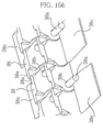
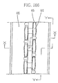
- FIG. 166 is a plan view of an internal circumference (non-ground contact surface) side showing an example of a conventional rubber crawler
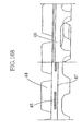
- FIG. 168 is a sectional view taken along the X-X line in FIG. 166
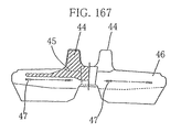
- FIG. 167 is a sectional view taken along the Y-Y line in FIG. 166
- reference numeral 44 denotes a core metal guide projection
- reference numeral 45 denotes a core metal
- reference numeral 46 denotes a rubbery elastic body
- reference numeral 47 denotes a tension reinforcement layer.
- the rod body and the through-hole of the rectangular parallelepiped block are fixed via an elastic material, they are fixed more firmly as compared with the conventional rubber crawler, and derailing of the rubber crawler can be decreased dramatically with extremely less vibration, thus making it possible to decrease swing of the individual rod body and decrease vibration.
- the rod body revolves via a rubber layer between the rod body and the through-hole of the rectangular parallelepiped block, and thus friction between the through-hole of the rectangular parallelepiped block and the rod body is avoided, thus preventing abrasion, and preventing occurrence of a squeaking sound.
- spring steel, steel cord, or high strength fiber are usable, which gives springiness to the connecting ring, prevents abnormal tension, and provides the rubber crawler to which breakage is hardly occurs, but it is possible to form by the material other than them.
- a rib may be provided on the surface of the wing portion on the inner circumference side, which is formed at the connecting ring, and this rib makes it possible to reinforce the wing portion of the connecting ring.
- a center rib connecting the ground contact surface side and the inner circumference side may be formed at the center part of the connecting ring, whereby the connecting ring is reinforced, and the strength of the connecting ring is improved, to make it effective to be used in the outer roller type of crawler device.
- the connecting member is made a connecting block in a block form, instead of the connecting ring in a ring form.
- the insertion hole provided in the connecting block is made larger than the outer diameter of the rod body, and the rod body is fixed via the rubber material as an elastic material in a gap between the insertion hole and the rod body, the rubber crawler is given extension to some degree and springiness, and abnormal tension hardly occurs while the rod body is firmly fixed, thus making the rubber crawler difficult to derail with less vibration.
- the insertion hole provided in the connecting block may be made larger at the sprocket engaging hole side, and made smaller at the other side as the through-hole of the rectangular parallelepiped block, and an inner projection may be provided on an inner wall of the insertion hole which is made larger, thus making it possible to further reduce the twist of the rubber crawler and the swing of the rod body.
- the rod body may be integrally formed at the connecting member or the rectangular parallelepiped block, and further, all of the rod body, the connecting member, the rectangular parallelepiped block and the bush may be integrally formed, whereby the number of components can be reduced, the assembly operation steps is reduced at the time of production, and the assembly operation is facilitated, thus making it possible to simplify the number of man-hours for the operation and reduce the cost.
- the rubber crawler of the present invention is not limited to the endless and integral construction, but a rubber crawler unit as the minimum unit, which is constructed by a rubber crawler unit of the minimum unit constructed by the rectangular parallelepiped block and the rod body, may be formed, or a rubber crawler unit as the minimum unit, which is constructed by two of the rectangular parallelepiped blocks and one rod body may be formed, the connecting through-holes may be provided at the end portion of the rubber crawler unit in the crawler circumference direction, and the connecting rod body may be inserted through the through-hole to be connected to connect the rubber crawler units, whereby an endless rubber crawler may be made.
- the connecting insertion holes may be provided in addition to the connecting through-holes.
- the rubber crawler unit other than the rubber crawler unit as the minimum unit constructed by the rectangular parallelepiped block and the rod body, the rubber crawler unit constructed by two of the rectangular parallelepiped blocks and one rod body, the rubber crawler unit constructed by two of the rectangular parallelepiped blocks and one rod body, and two of the connecting members, and rubber crawler unit constructed by a plurality of the rectangular parallelepiped blocks and a plurality of the rod bodies, or by a plurality of the rectangular parallelepiped blocks, a plurality of the rod bodies and a plurality of the connecting members, with the required length, are formed, and only the same kind of rubber crawler units may be connected to be endless, or rubber crawler units with various constructions are formed, and these rubber crawler units may be properly combined and connected to make an endless form, or both end portions of one rubber crawler unit may be connected to make an endless rubber crawler.
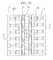
- the connecting rings 15 are placed in a zigzag fashion by being displaced by a half pitch from the rectangular parallelepiped blocks 5 in the crawler circumference direction, and placed at the outer side of the rectangular parallelepiped blocks 5 in the crawler width direction, and they are buried in the rubber crawler main body 3 by inserting the adjacent rod bodies 4 and 4 through insertion portions 15a and 15a at both sides of the connecting rings 15 in order.
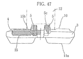
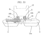
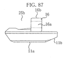
- a top surface of the connecting block 16 is in a flat form, and is exposed on the rubber crawler inner circumference side 10 (non-ground contact surface side), or coated with such rubber as a flash to be a rolling contact surface 16b , on which the outer track roller 12 included in the machine body can roll to travel.
- FIG. 61 is a plan view of the ground contact side of the rubber crawler unit 17
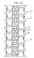
- FIG. 62 is a plan view of a partial ground contact side of a rubber crawler which is formed by connecting the rubber crawler units 17 to be endless.
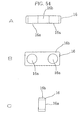
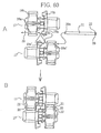
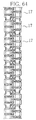
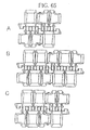
- connection of the rubber crawler units only the same kind of rubber crawler units shown in FIGS. 65A and B may be connected to be a rubber crawler in an endless form, or rubber crawler units of different lengths shown in FIG. 65C may be connected to form a rubber crawler in an endless form, and the rubber crawler units may be appropriately selected according to the length of the circumference of the required rubber crawler to perform connection to form a rubber crawler in an endless form.
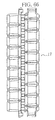
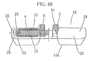
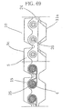
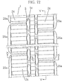
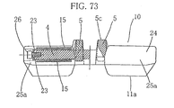
- the sixteenth embodiment has the construction in which the belt body 25 formed at the outer side portion of the rectangular parallelepiped block 5 in the crawler width direction of the rubber crawler skeleton part 6 is divided into two belt bodies 25a with ends.
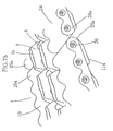
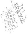
- the position at which the belt body 25 is divided is not limited to this embodiment, but it is optional, and another embodiment of the division is shown in FIG. 76 .
- the belt body 25 is not limited to the construction in which it is divided into two, but the construction in which the belt body 25 is divided into three or more belt bodies with ends, which include three or more rod bodies 4 , may be suitable.
- the rubber crawler of this embodiment is replaceable by a division unit when the belt body 25a with an end at the outer side portion of the rectangular parallelepiped block 5 is damaged.
- FIG. 80 Another example of this embodiment is shown in FIG. 80 .
- the rubber crawler of this embodiment has a bush 5g integrally formed at the inner side in the width direction of the rectangular parallelepiped block 5 , and the bushes 5g are joined together to set the space between the rectangular parallelepiped blocks 5 .
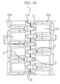
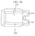
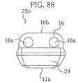
- the rubber crawler of this embodiment is formed so that the belt unit 25b is made attachable and detachable to and from the rubber crawler skeleton part 6 constituted by the rod bodies 4 and the rectangular parallelepiped blocks 5 .
- FIG. 90 Another example of the connecting block 16 is shown in FIG. 90 , the central wing portion 16d is formed only at the portion corresponding to the engaging part and is divided into two.
- the connecting block 16 embedded in the used belt unit 25b after replacement is reclaimed, and it is easy to bond the rubber elastic body 24 to it by vulcanization once again, thus making it possible to provide a rubber crawler that is also friendly to the environment in terms of recycling.
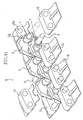
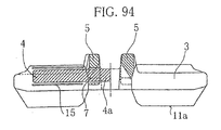
- FIG. 94 is a sectional view of the rubber crawler 1 of the nineteenth embodiment in the crawler width direction
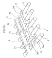
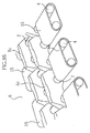
- FIG. 95 is a view of combination of the rubber crawler skeleton part 6 (the rod bodies 4 , the rectangular parallelepiped blocks 5 , and the connecting rings 15 ) which are embedded in the rubber crawler main body 3 .
- both end portions in the crawler width direction are located at a center side from the outer end portion of the connecting ring 15 in the rubber crawler width direction.
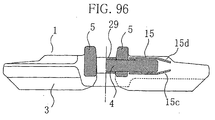
- FIG. 96 Another example of the nineteenth embodiment of the present invention is shown in FIG. 96 .
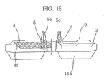
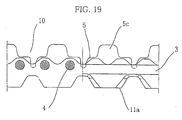
- This embodiment is characterized in that as for the outer end portion of the connecting ring 15 in the rubber crawler width direction, an end portion at the outer circumference side is folded toward the inner circumference side to provide an inclined surface 15c at the outer circumference side, and an end portion at the inner circumference side is folded toward the outer circumference side, whereby an inclined surface 15d is provided at the inner circumference side.
- the inclined surface area increases as compared with the one provided with the inclined surface 4d at the rod body 4 , and breakage (edge tearing) of both end portions in the rubber crawler width direction, which is caused by the rubber crawler riding on a curbstone and the like on the road surface is prevented further effectively, thus improving durability of the both end portions in the rubber crawler width direction.
- Reference numeral 29 in the drawing is a bush fitted onto the machine body 4 .
- the discrete bush 29 is fitted.
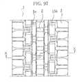
- FIG. 97 to FIG. 101 are the drawings showing the rubber crawler 1 of the twentieth embodiment of the present invention
- FIG. 97 is a plan view showing the inner circumference of the rubber crawler 1 of the twentieth embodiment
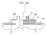
- FIG. 98 is a sectional view taken along the X-X line in FIG. 97
- FIG. 99 is a perspective view of combination of a core metal (the rod bodies 4 , the rectangular parallelepiped blocks 5 and the connecting rings 15 ) being the crawler skeleton part 6 which is provided in the rubber crawler main body 3
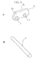
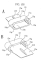
- FIGS. 100A and B are perspective views of the connecting ring 15
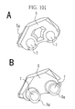
- FIGS. 101A and B are perspective views of the rectangular parallelepiped block 5 .
- the connecting ring 15 of this embodiment is formed so that the width of the connecting ring 15 in the crawler width direction is made small, the wing portion 15e is provided only at the outer circumference side to make the outer circumference side of the connecting ring 15 wider and the inner circumference side narrower. This is to increase resistance to deformation by increasing the area of the ground contact side to which a load is always applied.
- the inner circumference side to which a load is not applied is made narrower, so that the weight is reduced and assembly operation is facilitated. By reducing the amount of the materials, the production cost is reduced. Further, the rod body 4 is also made shorter, the weight is reduced and the material cost is further reduced.
- a rib 15f is provided at the inner circumference side of the wing portion 15e of the connecting ring 15 to reinforce the wing portion 15e of the connecting ring 15 .
- the rolling contact surface 15b for the rollers is provided on the inner circumference side of the connecting ring 15 so that the outer roller type of rollers and the like can roll thereon, and further, a stabilizer projection 15g is provided in the insertion portion 15a , so that the rod body 4 is prevented from swinging more than a fixed amount in the vertical (the ground contact surface to the non-ground contact surface side) direction and in the extending direction in the crawler circumference direction.
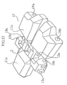
- the bush 5g is integrally formed at the rectangular parallelepiped block 5 of this embodiment, and the number of components is reduced, thus facilitating assembly and reducing cost.
- FIG. 102 to FIG. 104 show a twenty-first embodiment of the present invention.
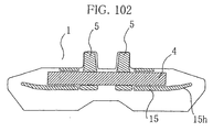
- FIG. 102 is a sectional view in the crawler width direction of a rubber crawler
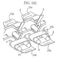
- FIG. 103 is a perspective view of combination of the rubber crawler skeleton part 6 (the rod bodies 4 and the rectangular parallelepiped blocks 5 , and the connecting rings 15 ) which is provided in the rubber crawler main body 3
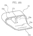
- FIG. 104 is a perspective view of the connecting ring 15 which is embedded in the rubber crawler main body 3 .
- an end portion of the wing portion 15e of the connecting ring 15 in the width direction of the rubber crawler is folded to the inner circumference side to provide an inclined surface 15h at the outer circumference side, so that breakage (edge tearing) of both the end portions in the width direction of the rubber crawler, which is caused by the rubber crawler riding on a curbstone and the like of the road surface, is prevented.
- a center rib 15i which connects the outer circumference (ground contact surface) side and the inner circumference (non-ground contact surface) side, is formed in a center part of the connecting ring 15 , whereby the connecting ring 15 is reinforced, and the strength of the connecting ring is improved, thus making it effective when the connecting ring 15 is used for the outer roller type of crawler device.
- the connecting ring 15 can be reinforced.
- it is possible to decrease the wall thickness of the connecting ring 15 whereby the production cost is reduced and the connecting ring at low price with high strength can be produced.
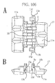
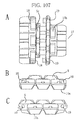
- FIGS. 106A and B , and FIGS. 107A to C are views each showing a rubber crawler unit 17 of the twenty-second embodiment of the present invention
- FIG. 106A is a plan view showing an outer circumference side
- B is a front view
- FIG. 107A is a plan view showing an inner circumference side
- B and C are side views.
- FIGS. 108A and B , and FIG. 109 are views showing a core metal (the rod bodies 4 , the rectangular parallelepiped blocks 5 , and the connecting rings 15 ) which is the crawler skeleton part 6 that is embedded in the rubber crawler unit 17
- the length of the rod body 4 is about half the length of the length of the crawler width, and the end portion of the rod body 4 is not located at the end portion in the width direction of the crawler, whereby the end portion of the rod body can be prevented from being damaged by curbstones, the obstacles or the like on the traveling road surface, thus making it possible to prevent the fixtures at the connecting parts at both end portions in the circumference direction of the rubber crawler unit 17 from being damaged, and prevent the connecting part of the rubber crawler unit 17 from being detached by damage of the connecting part.
- Reference numeral 30 in the drawing denotes a concave groove provided in a rug ground contact surface.
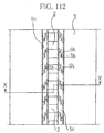
- FIG. 112 is a plan view of the inner circumference side of a rubber crawler
- FIG. 113 is a sectional view taken along the X-X line in FIG. 112
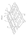
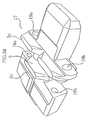
- FIG. 114 is a perspective view of the inner circumference side of the rubber crawler
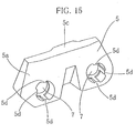
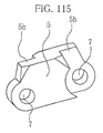
- FIG. 115 is a perspective view of the rectangular parallelepiped block 5 of this embodiment.
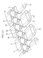
- the rectangular parallelepiped block 5 of this embodiment is formed so that the wall thickness of the through-hole region is thinner than the center part of the rectangular parallelepiped block 5 by providing a step portion 5h at the through-hole 7 region as shown in FIG. 115 .
- the step portions 5h are formed to be in the opposite directions to each other at the front and the rear in the longitudinal direction of the rectangular parallelepiped block, and as shown in FIG.
- the rectangular parallelepiped blocks 5 are placed to face each other with the sprocket engaging holes 2 between them, the step portions 5h of the adjacent rectangular parallelepiped block 5 are overlaid on each other, the rod bodies 4 are inserted through the thorough-holes 7 of the overlaid step portions 5h , the rod bodies 4 are connected with the rectangular parallelepiped block 5 to construct the rubber crawler skeleton part 6 in an endless form, which is provided in the rubber crawler main body 3 .
- This embodiment does not have to include connecting rings or reinforcement layers, since the rod body is connected with two of the rectangular parallelepiped blocks and the rod body is firmly connected.
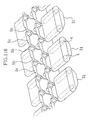
- FIG. 116 shows a twenty-fourth embodiment of the present embodiment, which is the drawing showing another example of the twenty-third embodiment, and is a perspective view of the inner circumference side of a rubber crawler.
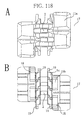
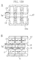
- FIG. 118A is a plan view showing the outer circumference (ground contact surface) side of the rubber crawler unit 17 of the twenty-fifth embodiment
- B is a plan view showing the inner circumference (non-ground contact surface) side
- FIG. 119 is a perspective view of combination of the skeleton part 6 (the rod bodies 4 , the rectangular parallelepiped blocks 5 , and the connecting rings 15 ) which is embedded in the rubber crawler unit 17 .
- the twenty-fifth embodiment is the rubber crawler unit 17 having the construction in which the step portions 5h are provided at the region of the through-holes 6 of the rectangular parallelepiped blocks 5 , so that the wall thickness of the through-hole regions is formed to be thinner than the center parts of the rectangular parallelepiped blocks 5 , by using the rectangular parallelepiped blocks 5 which is formed so that the step portions 5h are in the opposite direction at the front and the rear in the longitudinal direction of the rectangular parallelepiped block 5 , the rectangular parallelepiped blocks 5 are placed to face each other with the sprocket engaging holes 2 between them, the step portions 5h of the adjacent rectangular parallelepiped blocks 5 are overlaid on each other, the rod bodies 4 are inserted through the through-holes 7 of the overlaid step portions 5h , and the rod bodies 4 are connected with the rectangular parallelepiped blocks 5 , whereby the rubber crawler skeleton part is formed.
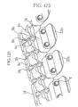
- FIGS. 128A and B are perspective views of the rectangular parallelepiped block 5 of another example
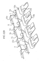
- FIG. 129 is a perspective view of combination of the core metal (the rod bodies 4 and the rectangular parallelepiped blocks 5 , and the connecting rings 15 ) being the skeleton part 6 which is provided in the rubber crawler main body 3 of another example.
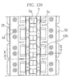
- FIG. 139 to FIG. 142 show a thirtieth embodiment of the present invention.
- FIG. 139 is a plan view of an inner circumference side
- FIG. 140 is a sectional view taken along the X-X line in FIG. 139
- FIG. 141 is a side view
- FIG. 142A is a sectional view of a rubber pad
- FIG. 142B is a plan view of an inner circumference side of the rubber pad.
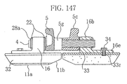
- FIG. 147 is the drawing showing still another example of the thirty-first embodiment, and is a sectional view of the rubber crawler.
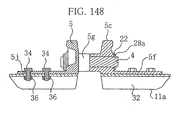
- FIG. 148 is a sectional view showing a thirty-second embodiment of the present invention.
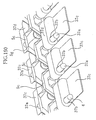
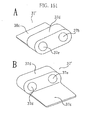
- FIG. 149 and FIG. 150 show a thirty-third embodiment of the present invention.
- FIG. 149 is a perspective view of a connecting block 37 of this embodiment
- FIG. 150 is a perspective view explaining combination of the core metal being the rubber crawler skeleton part 6 .
- the thirty-third embodiment is the one in which the rod body and the connecting block are integrally formed, a rod body 37a is projectingly formed at a position corresponding to one of the through-holes provided at the front and the rear in the rubber crawler circumference direction of the connecting block, and at the other position, a through-hole 37b is provided, and further, a wing portion 37c is formed at the opposite side of the rod body 37a .
- the rod body 37a projectingly provided and integrally formed is inserted through the through-hole 7 of the rectangular parallelepiped block 5 and the through-hole 37b of the connecting block 37 to connect the rod body 37a with the rectangular parallelepiped block 5 and the connecting block 37 , as shown in FIG. 150 , whereby the rubber crawler skeleton part is constructed.
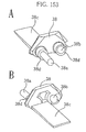
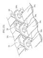
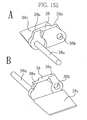
- the thirty-fifth embodiment is the one in which the rod body and the rectangular parallelepiped block are integrally formed, a rod body 38a is projectingly formed at a position corresponding to one of the through-holes provided at the front and the rear of the rectangular parallelepiped block in the rubber crawler circumference direction, and at the other position, a through-hole 38b is provided, and further, a wing portion 38c is formed at the opposite side of the rod body 38a .
- the rod body 38a projectingly provided and integrally formed is inserted through the through-hole 38a of the rectangular parallelepiped block 38 to connect the rod body 38a with the rectangular parallelepiped block 38 , as shown in FIG. 154 , whereby the rubber crawler skeleton part 6 is constructed.
- a bush 38d is integrally formed at the rectangular parallelepiped block 38 , and the number of components is further decreased to contribute to reduction in production cost.
- the reinforcement layer 14 in the outer circumference (ground contact surface) side of the wing portion 38c as shown in FIG. 154 , and the reinforcement layer 14 may be embedded in the inner circumference side of the wing portion 38c , or it may be embedded in both the outer circumference side and the inner circumference side. If only the longitudinally adjacent rectangular parallelepiped blocks can be connected, the reinforcement layers other than the above-described one may be used.
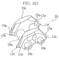
- the rectangular parallelepiped block 39 of the thirty-seventh embodiment is used in the rubber crawler skeleton structure with the construction in which a pair of rectangular parallelepiped blocks are arranged to face each other, and two rectangular parallelepiped blocks are integrally formed via bushes 39a engaging with the driving wheel (sprocket) of the endless crawler traveling equipment.
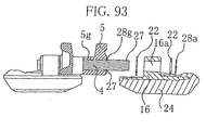
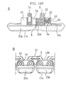
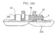
- grooves 27 are provided in both end portions of the connecting rod body 21 , and the washer 22 is fitted into the center side of the groove 27 in the crawler width direction, attach an E-shaped retaining ring 28b into the groove 27 with an exclusive tool to fix the connecting rod body 21 so that it is not detached, as shown in FIGS. 159A to C .
- the fixtures and fixing methods other than the above may be used, the present invention is not limited to the above fixtures and fixing methods, and it is suitable if only the rubber crawler unit connecting part, and the belt bodies (endless belt body, belt body with an end, belt unit) are favorably fixed.
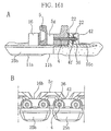
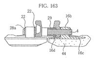
- the thirty-eighth embodiment is the one in which the fixtures used for fixing the rubber crawler unit connecting part and fixing the belt bodies (endless belt body, belt body with an end, belt unit) are buried into a fixture burying hole 42 provided inside the connecting ring 15 or the connecting block 16 . This prevents the fixtures from being damaged, and prevents the trouble of division and removal being impossible due to the fixtures being damaged at the time of connecting and dividing the rubber crawler unit connecting part, and attaching and detaching the belt bodies.
Landscapes
- Engineering & Computer Science (AREA)
- Chemical & Material Sciences (AREA)
- Combustion & Propulsion (AREA)
- Transportation (AREA)
- Mechanical Engineering (AREA)
- Processing Of Solid Wastes (AREA)
Applications Claiming Priority (7)
| Application Number | Priority Date | Filing Date | Title |
|---|---|---|---|
| JP2000141587 | 2000-05-15 | ||
| JP2000141587 | 2000-05-15 | ||
| JP2000265612A JP2002037154A (ja) | 2000-05-15 | 2000-09-01 | ゴムクローラ |
| JP2000265612 | 2000-09-01 | ||
| JP2000369653A JP2002173063A (ja) | 2000-12-05 | 2000-12-05 | ゴムクローラ |
| JP2000369653 | 2000-12-05 | ||
| PCT/JP2001/004054 WO2001087693A1 (en) | 2000-05-15 | 2001-05-15 | Rubber crawler |
Publications (2)
| Publication Number | Publication Date |
|---|---|
| EP1283152A1 true EP1283152A1 (de) | 2003-02-12 |
| EP1283152A4 EP1283152A4 (de) | 2004-09-29 |
Family
ID=27343376
Family Applications (1)
| Application Number | Title | Priority Date | Filing Date |
|---|---|---|---|
| EP01930169A Withdrawn EP1283152A4 (de) | 2000-05-15 | 2001-05-15 | Gummi gleiskette |
Country Status (3)
| Country | Link |
|---|---|
| EP (1) | EP1283152A4 (de) |
| AU (1) | AU2001256754A1 (de) |
| WO (1) | WO2001087693A1 (de) |
Cited By (9)
| Publication number | Priority date | Publication date | Assignee | Title |
|---|---|---|---|---|
| US9067631B1 (en) | 2010-12-14 | 2015-06-30 | Camoplast Solideal Inc. | Endless track for traction of a vehicle |
| US10272959B2 (en) | 2010-06-30 | 2019-04-30 | Camso Inc. | Track assembly for an off-road vehicle |
| US10328982B2 (en) | 2010-12-14 | 2019-06-25 | Camso Inc. | Drive sprocket, drive lug configuration and track drive arrangement for an endless track vehicle |
| US10783723B2 (en) | 2015-06-29 | 2020-09-22 | Camso Inc. | Systems and methods for monitoring a track system for traction of a vehicle |
| US10933877B2 (en) | 2010-12-14 | 2021-03-02 | Camso Inc. | Track drive mode management system and methods |
| US11046377B2 (en) | 2015-03-04 | 2021-06-29 | Camso Inc. | Track system for traction of a vehicle |
| US11835955B2 (en) | 2017-12-08 | 2023-12-05 | Camso Inc. | Systems and methods for monitoring off-road vehicles |
| US12090795B2 (en) | 2018-08-30 | 2024-09-17 | Camso Inc. | Systems and methods for monitoring vehicles with tires |
| US12254616B2 (en) | 2018-08-30 | 2025-03-18 | Camso Inc. | Systems and methods for monitoring tracked vehicles |
Families Citing this family (2)
| Publication number | Priority date | Publication date | Assignee | Title |
|---|---|---|---|---|
| ITMI20071618A1 (it) † | 2007-08-03 | 2009-02-04 | Rolic Invest Sarl | Impianto di trasporto a fune e metodo di azionamento dello stesso |
| KR101146092B1 (ko) | 2009-12-11 | 2012-05-15 | 한국카모플라스트(주) | 충격흡수 홈을 구성한 고무 크로라 |
Family Cites Families (7)
| Publication number | Priority date | Publication date | Assignee | Title |
|---|---|---|---|---|
| US1949423A (en) * | 1933-03-23 | 1934-03-06 | Harry A Knox | Track for tracklaying vehicles |
| US2738236A (en) * | 1951-07-23 | 1956-03-13 | Fred L Haushalter | Track construction |
| GB865812A (en) * | 1956-09-28 | 1961-04-19 | Luxembourg Brev Participations | Improvements in tracks for track-laying vehicles |
| US3282630A (en) * | 1964-11-20 | 1966-11-01 | Richard E Harrison | Endless track for powered vehicles |
| JPH0728067Y2 (ja) * | 1988-05-27 | 1995-06-28 | セイレイ工業株式会社 | バックホー等の走行部の履帯構造 |
| JP3193188B2 (ja) * | 1993-05-25 | 2001-07-30 | 株式会社ブリヂストン | ゴムクローラ |
| JPH08282556A (ja) * | 1995-04-11 | 1996-10-29 | Ohtsu Tire & Rubber Co Ltd :The | 分割式弾性クローラ |
-
2001
- 2001-05-15 AU AU2001256754A patent/AU2001256754A1/en not_active Abandoned
- 2001-05-15 EP EP01930169A patent/EP1283152A4/de not_active Withdrawn
- 2001-05-15 WO PCT/JP2001/004054 patent/WO2001087693A1/ja not_active Ceased
Cited By (20)
| Publication number | Priority date | Publication date | Assignee | Title |
|---|---|---|---|---|
| US11186330B2 (en) | 2010-06-30 | 2021-11-30 | Camso Inc. | Track assembly for an off-road vehicle |
| US10272959B2 (en) | 2010-06-30 | 2019-04-30 | Camso Inc. | Track assembly for an off-road vehicle |
| US9162718B2 (en) | 2010-12-14 | 2015-10-20 | Camso Inc. | Endless track for traction of a vehicle |
| US9878750B2 (en) | 2010-12-14 | 2018-01-30 | Camso Inc. | Endless track for traction of a vehicle |
| US10077089B1 (en) | 2010-12-14 | 2018-09-18 | Camso Inc. | Endless track for traction of a vehicle |
| US10328982B2 (en) | 2010-12-14 | 2019-06-25 | Camso Inc. | Drive sprocket, drive lug configuration and track drive arrangement for an endless track vehicle |
| US10730572B1 (en) | 2010-12-14 | 2020-08-04 | Camso Inc. | Endless track for traction of a vehicle |
| US12583458B2 (en) | 2010-12-14 | 2026-03-24 | Camso Inc. | Track drive mode management system and methods |
| US10843750B2 (en) | 2010-12-14 | 2020-11-24 | Camso Inc. | Endless track for traction of a vehicle |
| US10933877B2 (en) | 2010-12-14 | 2021-03-02 | Camso Inc. | Track drive mode management system and methods |
| US9067631B1 (en) | 2010-12-14 | 2015-06-30 | Camoplast Solideal Inc. | Endless track for traction of a vehicle |
| US12049267B2 (en) | 2010-12-14 | 2024-07-30 | Camso Inc. | Endless track for traction of a vehicle |
| US11046377B2 (en) | 2015-03-04 | 2021-06-29 | Camso Inc. | Track system for traction of a vehicle |
| US11897558B2 (en) | 2015-03-04 | 2024-02-13 | Camso Inc. | Track system for traction of a vehicle |
| US11167810B2 (en) | 2015-03-04 | 2021-11-09 | Camso Inc. | Track system for traction of a vehicle |
| US12008846B2 (en) | 2015-06-29 | 2024-06-11 | Camso Inc. | Systems and methods for monitoring a track system for traction of a vehicle |
| US10783723B2 (en) | 2015-06-29 | 2020-09-22 | Camso Inc. | Systems and methods for monitoring a track system for traction of a vehicle |
| US11835955B2 (en) | 2017-12-08 | 2023-12-05 | Camso Inc. | Systems and methods for monitoring off-road vehicles |
| US12090795B2 (en) | 2018-08-30 | 2024-09-17 | Camso Inc. | Systems and methods for monitoring vehicles with tires |
| US12254616B2 (en) | 2018-08-30 | 2025-03-18 | Camso Inc. | Systems and methods for monitoring tracked vehicles |
Also Published As
| Publication number | Publication date |
|---|---|
| WO2001087693A1 (en) | 2001-11-22 |
| AU2001256754A1 (en) | 2001-11-26 |
| EP1283152A4 (de) | 2004-09-29 |
Similar Documents
| Publication | Publication Date | Title |
|---|---|---|
| US7377601B2 (en) | Detachable crawler | |
| KR100592817B1 (ko) | 고무 크롤러 | |
| EP1283152A1 (de) | Gummi gleiskette | |
| EP3116770B1 (de) | Fahrzeugraupenanordnung mit konischen rädern | |
| US7066562B2 (en) | Grouser shoe and fabrication method | |
| JP3901505B2 (ja) | 弾性体履板 | |
| JP2001334972A (ja) | ゴムクローラ | |
| KR100342854B1 (ko) | 탈착식 패드 | |
| US5984437A (en) | Connecting link type rubber crawler | |
| US6450593B2 (en) | Elastic crawler shoe for discharging snow | |
| JP4078078B2 (ja) | ゴムクローラ | |
| JP2595443Y2 (ja) | 無限軌道帯用履板 | |
| JP2002037154A (ja) | ゴムクローラ | |
| JPH06316280A (ja) | 連結リンク式ゴムクローラ | |
| JPH082456A (ja) | 金属製クローラの履板用弾性パッド | |
| JPH11180356A (ja) | 無限軌道履帯用履板 | |
| JPH0730186U (ja) | 無限軌道帯用弾性履板 | |
| JPH07257446A (ja) | 連結リンク式ゴムクローラ及びその接続方法並びに補修方法 | |
| JPH01115781A (ja) | 履帯駆動装置及び履帯車両を改装する方法 | |
| JPH10194171A (ja) | 無限軌道帯の弾性体履板 | |
| JPH08119159A (ja) | 弾性体履板 | |
| JPH0597073A (ja) | ゴムクロ−ラユニツト | |
| JPH11180355A (ja) | 無限軌道帯用超小型履帯 | |
| JPH06115467A (ja) | クローラシュー用ゴムパッド及びゴムクローラ | |
| KR19990021210U (ko) | 무한궤도용 슈 |
Legal Events
| Date | Code | Title | Description |
|---|---|---|---|
| PUAI | Public reference made under article 153(3) epc to a published international application that has entered the european phase |
Free format text: ORIGINAL CODE: 0009012 |
|
| 17P | Request for examination filed |
Effective date: 20021118 |
|
| AK | Designated contracting states |
Designated state(s): AT BE CH CY DE DK ES FI FR GB GR IE IT LI LU MC NL PT SE TR |
|
| RBV | Designated contracting states (corrected) |
Designated state(s): DE FR GB IT |
|
| A4 | Supplementary search report drawn up and despatched |
Effective date: 20040818 |
|
| GRAP | Despatch of communication of intention to grant a patent |
Free format text: ORIGINAL CODE: EPIDOSNIGR1 |
|
| STAA | Information on the status of an ep patent application or granted ep patent |
Free format text: STATUS: THE APPLICATION IS DEEMED TO BE WITHDRAWN |
|
| 18D | Application deemed to be withdrawn |
Effective date: 20060930 |