EP0732300A2 - Engin mobile de travail - Google Patents
Engin mobile de travail Download PDFInfo
- Publication number
- EP0732300A2 EP0732300A2 EP96103767A EP96103767A EP0732300A2 EP 0732300 A2 EP0732300 A2 EP 0732300A2 EP 96103767 A EP96103767 A EP 96103767A EP 96103767 A EP96103767 A EP 96103767A EP 0732300 A2 EP0732300 A2 EP 0732300A2
- Authority
- EP
- European Patent Office
- Prior art keywords
- supports
- tool according
- support
- chassis
- support wheel
- Prior art date
- Legal status (The legal status is an assumption and is not a legal conclusion. Google has not performed a legal analysis and makes no representation as to the accuracy of the status listed.)
- Granted
Links
Images

Classifications
-
- B—PERFORMING OPERATIONS; TRANSPORTING
- B66—HOISTING; LIFTING; HAULING
- B66C—CRANES; LOAD-ENGAGING ELEMENTS OR DEVICES FOR CRANES, CAPSTANS, WINCHES, OR TACKLES
- B66C23/00—Cranes comprising essentially a beam, boom, or triangular structure acting as a cantilever and mounted for translatory of swinging movements in vertical or horizontal planes or a combination of such movements, e.g. jib-cranes, derricks, tower cranes
- B66C23/62—Constructional features or details
- B66C23/72—Counterweights or supports for balancing lifting couples
- B66C23/78—Supports, e.g. outriggers, for mobile cranes
- B66C23/80—Supports, e.g. outriggers, for mobile cranes hydraulically actuated
-
- B—PERFORMING OPERATIONS; TRANSPORTING
- B66—HOISTING; LIFTING; HAULING
- B66F—HOISTING, LIFTING, HAULING OR PUSHING, NOT OTHERWISE PROVIDED FOR, e.g. DEVICES WHICH APPLY A LIFTING OR PUSHING FORCE DIRECTLY TO THE SURFACE OF A LOAD
- B66F11/00—Lifting devices specially adapted for particular uses not otherwise provided for
- B66F11/04—Lifting devices specially adapted for particular uses not otherwise provided for for movable platforms or cabins, e.g. on vehicles, permitting workmen to place themselves in any desired position for carrying out required operations
- B66F11/044—Working platforms suspended from booms
- B66F11/046—Working platforms suspended from booms of the telescoping type
Definitions
- a mobile work tool of the type mentioned is known from DE-TEUPEN BROCHURE: Telescopic work platform TL 23 and TL 23h.
- a lifting arm with a work cage is arranged on a chassis.
- the chassis is a car single-axle trailer with wheels attached on both sides. Instead of a single-axle car trailer, an industrial chassis or a chassis with chains or the like can be arranged.
- the chassis has a slewing ring in the middle on which the lifting arm can be pivoted.
- At the corners of the chassis there are supports that are height-adjustable with hydraulic cylinders.
- a drawbar is permanently mounted between two supports, with which the implement can be pulled from one place of work to another with the help of a towing vehicle.
- a support wheel is arranged on the drawbar.
- the drawbar is arranged as an additional and separate part on the chassis. With to be carried out Working, the drawbar is also a disturbing element. Their length determines how far the implement is to be placed at a distance from buildings or the like. This means that either the implement must be positioned differently again or the maximum possible use, formed by the maximum lateral outreach times the maximum basket load, cannot be used.
- a mobile work device is also known from DE-U-9 202 227.
- a superstructure is positioned on a chassis.
- the chassis carries wheels on both sides.
- Two supports are attached next to the wheels.
- a third support is formed by a drawbar opposite a fourth support.
- the supports are adjusted with hydraulic cylinders.
- a support wheel is positioned on the drawbar.
- the advantages achieved with the invention consist in particular in that two supports attached to the corners of the chassis are connected to form a triangular drawbar unit.
- the two adjustment devices ensure that the triangular drawbar unit can be adjusted so that it can be adapted to the height of the respective trailer coupling. It is therefore possible to have the mobile work tool towed by both a car and a truck without additional changes. This increases the maneuverability of the mobile implement.
- the two adjustment devices ensure that the triangular drawbar unit is constantly held firmly in the respective pull position and behaves like a drawbar rigidly attached to the chassis.
- the two supports are articulated essentially on the outer corners of the chassis ensures that they can have the same length for a working position.
- the other supports can also be of the same length. Due to the almost square configuration of the chassis, at the corners of which the supports are positioned, the maximum reach and maximum superstructure load can be used thanks to the same length. This means that there are equally good maximum possible uses on all sides. Furthermore, by rotating the support cross by about 45 ° with respect to the axial direction of the wheels or the longitudinal axis of the vehicle, the width of the support cross is reduced and thus takes up less traffic space.
- the connecting device which holds the two supports together at their free ends, can consist of a toggle lever element which engages in a hook eye. This enables a simple and quick connection of both supports to a drawbar unit.
- connection devices such as Hydraulic devices, screw devices or the like can be used.
- a toggle lever element is arranged on one of the outer sides and in the region of the free end of the two supports.
- a clamping hook element can be installed on one of the outer sides of the essentially triangular support bracket. This form of locking ensures that the triangular drawbar unit can be released into two separate supports again by releasing one of the toggle levers.
- the triangular support bracket can remain attached to one of the supports.
- the triangular support bracket is disruptive when performing work, e.g. on soft ground and the like, it can also be removed from the other support.
- a trailer coupling can be arranged on the trailer console. It is advantageously held on the support bracket by special fastening elements. Of course, it is also possible to weld the trailer coupling to the support bracket.
- the two supports arranged on the opposite free side with their adjusting devices are pivoted into the transport position and held in a locking device. This ensures that the two rear supports cannot pivot outwards on their own during transport. Together with the superstructure brought into the transport position, they form a transport unit. In addition, the retracted rear supports serve as a break-in protection.
- the arrangement of the support wheel construction is relatively close to the transport axis, which carries both wheels. As a result, the support wheel takes up to a third of the total weight of the mobile implement. This relieves the load on the transport wheels, which is particularly noticeable on floors that are sensitive to loads.
- the arrangement of the support wheel including attachment to the chassis is advantageous if the drawbar unit are also designed as stabilizing supports for the implement. When adjusting the height of the supports, adjustment of the support wheel can then be dispensed with.
- the actuating unit consists of an adjusting element on which a steering lever element and the support wheel unit are arranged.
- the actuator is held by the support wheel linkage. This makes it possible for the support wheel to be retracted or extended in a simple manner. If the jockey wheel is extended to the ground, the steering directly on the jockey wheel enables the implement to be pivoted.
- an extension aid is integrated in the adjustment element.
- the extension aid can be a compression spring, a gas accumulator, an oil pressure accumulator or a controlled hydraulic cylinder.
- the motor unit is preferably designed as a hydraulic or electric motor.
- support plates are arranged at their ends via fastening tabs.
- the adjusting devices or the adjusting member can be designed as fluid motors, pneumatic cylinders or fluid cylinders, in particular as hydraulic cylinders. This ensures precise and precise adjustment of the individual supports.
- the lifting arm can be designed as a telescopic mast. This makes it possible to precisely adapt the lifting arm to the respective operating heights and the necessary transport position.
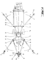
- the substructure is designed as a chassis 5, which is designed as a frame construction.
- the chassis bears wheels 15 and 16 on both sides. In the area of the axle drawn through the wheels, the chassis supports are tapered.
- a slewing ring 25 is arranged in the waisted area of the chassis 5.
- a lifting arm 26 is positioned on the turntable 25, which carries a work cage 28 and which form the superstructure 10.
- free chassis sides 36 and 37 are part of the chassis 5. They are realized by girders which are connected to the two waisted girders using intermediate bracket girders.
- At the outer corners of the free chassis sides 36 and 37 supports 1, 2, 3 and 4 are articulated.
- the supports are held on the chassis 5 via rotary pivot bearings 17, 18, 19 and 20.
- the support pivot bearings allow the supports to be swiveled sideways by hand.
- Each support 1, ... consists of a longer and a shorter partial support, which are angled together. This gives the supports the shape of an angled leg, which can be supported on a floor with its shorter end.
- a cylinder support element 32, 33 is arranged approximately in the middle of the longer partial support of the supports 1, ....
- a U-shaped support part 34, 35 is placed and fastened around each of the support pivot bearings 17,.. This enables the pivoting possibility about an axis element in the support pivot bearing 17,.
- a hydraulic cylinder 21, 22, 23, 24 is fastened between the opposite bracket of the support part 34, 35 and the support cylinder receiving element 32, 33 on the support 1, ...
- the supports 1, ... each have a support plate 11, 12, 13, 14, which are held in fastening tabs.
- the supports 1, 2, 3, 4 thus described have a rune-shaped wedge shape formed by the two partial supports. This makes it possible to provide support across obstacles.
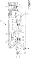
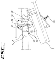
- a toggle lever element 81 or 91 is fastened to the outside 1, 'or 4', as shown in particular also in FIG. 3.
- the toggle lever element 81 or 91 has an eccentric device 83 which is attached to a plate 85 which is fastened to the respective support 1 or 4 with special connecting elements.
- Component of the connecting device 7 and 8 are clamping hook eyelets 82 and 92, respectively, which are held on the outside of an essentially triangular support bracket 31.
- the support bracket carries a trailer coupling 9.
- a support wheel linkage 59 is arranged on the chassis 5 relatively close to the support wheel construction to the transport axis, which carries the wheels 15, 16.
- the support wheel linkage 59 holds an adjusting member 50 which can be adjusted vertically essentially at right angles to the horizontal pull axis.
- the adjusting member 50 can be designed as a mechanical spindle or an electrically operated spindle. However, like positions 21 and 24, it can also be a hydraulic cylinder.
- a steering lever element 54 is attached to the vertical adjusting member 50 via a pivot bearing 53 and protrudes to the side in the direction of travel.
- the support wheel 38 is fastened to the steering lever element 54.
- the support wheel 38 can consist of one or a pair of wheels.
- the support wheel 38 is driven by a motor unit 52, which is designed as a hydraulic or electric motor.
- the motor is controlled by an actuating element integrated in the steering lever element 54, which can be a shift linkage or a shift element.
- An extension aid 56 is integrated in the adjusting member 50, which facilitates the raising from the transport position into the rest position or vice versa.
- the extension aid 56 can be a compression spring, a gas accumulator, a pressure accumulator or a controlled hydraulic cylinder.
- the mobile work device With a vehicle, such as a car or truck, the mobile work device is pulled out for a job.
- the adjusting member 50 which is designed as a hydraulic cylinder, is first subjected to hydraulic oil, so that the stable support wheel 38 moves so far down that it touches the ground.
- the mobile implement is released from the towing vehicle by actuating the trailer coupling. Because the support wheel construction is relatively close to the transport axis, which is supported by the wheels 16, the support wheel 38 1/3 and the wheels 15, 16 2/3 of the total weight G. This makes the wheels 15, 16, with which mainly the transport is carried out, effectively relieved.
- the motor unit 52 is activated by actuating an actuating element. By means of in the direction of travel the chassis 5 is steered to the side projecting steering lever element 54. A forward, backward and / or pivoting movement can be carried out very easily in this way, so that the implement can be set up on the site in the most precise manner.
- each support is individually adjustable in height, so that the chassis 5 can be adjusted exactly horizontally as a substructure.
- a spirit level is installed on the chassis.
- the lifting arm 26 is then raised and opened with the aid of a hydraulic cylinder 27.
- the work basket 28 itself is adjustable via a hydraulic cylinder 29.
- the lifting arm 26 consists of three aluminum profiles that are roller-mounted and can be moved in and out evenly by means of internal hydraulic cylinders with associated chains. The chains (not shown) are monitored by safety switches. Due to the hydrostatic parallel guidance of the hydraulic cylinder 29 on the work basket 28, it is always kept horizontal.
- the triple extended arm 26 rotates on the turntable 25 on the chassis 5.
- the range of rotation is 450 °. All movements are hydraulic, with pressure generated by a pump powered by a 220 volt AC motor.
- a work controller is located in the work basket 28.
- the lifting arm 26 is rotatable.
- the special design of the support system ensures that even a gradient, eg approx. 14%, can be compensated for. Due to the equally long supports 1, 2, 3, 4, it is possible to use the maximum lateral reach multiplied by the maximum lifting arm load in every rotational position.
- the supports 1 In confined spaces, such as narrow one-way streets, the supports 1, ... partially, i.e. ⁇ 45 °, e.g. 15 °, in relation to the longitudinal axis. Each support must be folded out as far as the space allows.
- an intermediate position of the folding angle of the supports is provided at approximately 20 ° to the longitudinal or wheel axis by means of a latching position.
- the lifting arm 26 When the work is finished, the lifting arm 26 is retracted and positioned approximately at right angles to the axis passing through the wheels 15 and 16. The work basket 28 is then retracted. By operating the hydraulic cylinders 21, ... the supports 1, ... are raised so that the chassis is held by the wheels 16 and the support wheel 38.
- the implement is then moved out of the work area with the aid of the steering lever element 54 and by actuating the motor unit 52 with the aid of the actuating element.
- the supports 2 and 3 are pivoted and locked by hand from the support position A in the direction of the basket 28.
- the locked supports 2 and 3 form a run-in protection.
- the entry protection prevents, for example, the entry of a cyclist into the otherwise free space.
- the other two supports 1 and 4 which were likewise brought into a transport position T by the hydraulic cylinders 21 and 24, are brought together.
- a joint is used Help of the eccentric joint device ensures that the supports 1 and 4 are firmly connected to one another and thus form the triangular drawbar unit 6.
- the trailer coupling 9 protruding towards the front, the team can be formed. It is essential that the height adjustment of the two hydraulic cylinders 21 and 24 enables the trailer coupling to be raised or lowered so that either a car or a truck or any other tractor can transport the mobile implement.
- the towing vehicle is moved up and the trailer coupling 9 is anchored to the vehicle.
- the start-up process of the adjusting member 50 is initiated by actuating the blocking valve.
- the extension aid 56 With the aid of the extension aid 56, the extended piston of the hydraulic cylinder of the adjusting member 50 is pressed upward. This ensures that the piston is at the same time firmly locked in the hydraulic cylinder and the adjusting member 50 and the retracted support wheel can be moved safely over uneven floors and the like.
Landscapes
- Engineering & Computer Science (AREA)
- Structural Engineering (AREA)
- Mechanical Engineering (AREA)
- Life Sciences & Earth Sciences (AREA)
- Geology (AREA)
- Forklifts And Lifting Vehicles (AREA)
Applications Claiming Priority (4)
| Application Number | Priority Date | Filing Date | Title |
|---|---|---|---|
| DE19509292 | 1995-03-15 | ||
| DE19509292A DE19509292C1 (de) | 1995-03-15 | 1995-03-15 | Mobiles Arbeitsgerät |
| DE29505173U | 1995-03-27 | ||
| DE29505173U DE29505173U1 (de) | 1995-03-27 | 1995-03-27 | Mobiles Arbeitsgerät |
Publications (3)
| Publication Number | Publication Date |
|---|---|
| EP0732300A2 true EP0732300A2 (fr) | 1996-09-18 |
| EP0732300A3 EP0732300A3 (fr) | 1997-03-26 |
| EP0732300B1 EP0732300B1 (fr) | 2000-01-12 |
Family
ID=26013377
Family Applications (1)
| Application Number | Title | Priority Date | Filing Date |
|---|---|---|---|
| EP96103767A Expired - Lifetime EP0732300B1 (fr) | 1995-03-15 | 1996-03-11 | Engin mobile de travail |
Country Status (3)
| Country | Link |
|---|---|
| EP (1) | EP0732300B1 (fr) |
| DE (1) | DE59604146D1 (fr) |
| DK (1) | DK0732300T3 (fr) |
Cited By (2)
| Publication number | Priority date | Publication date | Assignee | Title |
|---|---|---|---|---|
| EP0972743A1 (fr) * | 1998-07-13 | 2000-01-19 | Dino Lift Oy | Séries de produit comme plate-formes de travail monteé sur remorque |
| EP0945399A3 (fr) * | 1998-03-26 | 2002-07-10 | B. Teupen Maschinenbaugesellschaft mbH | Plate-forme de travail mobile à trois véhicules |
Families Citing this family (1)
| Publication number | Priority date | Publication date | Assignee | Title |
|---|---|---|---|---|
| US12528320B2 (en) | 2020-10-13 | 2026-01-20 | Fast Global Solutions, Inc. | Cam-actuated lift assist for tow bar activated brake system |
Family Cites Families (5)
| Publication number | Priority date | Publication date | Assignee | Title |
|---|---|---|---|---|
| DE1718292U (de) * | 1955-12-29 | 1956-03-08 | Int Baumaschinenfabrik A G | Stuetz- und ablageeinrichtung fuer fahrbare drehkrane. |
| US4397373A (en) * | 1982-01-25 | 1983-08-09 | Ream Michael D | Mobile pedestal scaffold |
| DE8524989U1 (de) * | 1985-08-31 | 1985-10-17 | Albert Böcker GmbH & Co KG, 4712 Werne | Aus mehreren Führungsschienen gebildeter Schrägaufzug |
| DK151304C (da) * | 1985-11-20 | 1988-05-16 | Hansen & Skov As | Transportabel personlift |
| DE9014713U1 (de) * | 1990-10-24 | 1991-04-11 | Neswadba, Peter, O-8030 Dresden | Fahrgestell für eine höhenverstellbare Arbeitsbühne |
-
1996
- 1996-03-11 DE DE59604146T patent/DE59604146D1/de not_active Expired - Fee Related
- 1996-03-11 DK DK96103767T patent/DK0732300T3/da active
- 1996-03-11 EP EP96103767A patent/EP0732300B1/fr not_active Expired - Lifetime
Cited By (2)
| Publication number | Priority date | Publication date | Assignee | Title |
|---|---|---|---|---|
| EP0945399A3 (fr) * | 1998-03-26 | 2002-07-10 | B. Teupen Maschinenbaugesellschaft mbH | Plate-forme de travail mobile à trois véhicules |
| EP0972743A1 (fr) * | 1998-07-13 | 2000-01-19 | Dino Lift Oy | Séries de produit comme plate-formes de travail monteé sur remorque |
Also Published As
| Publication number | Publication date |
|---|---|
| DK0732300T3 (da) | 2000-07-03 |
| EP0732300A3 (fr) | 1997-03-26 |
| EP0732300B1 (fr) | 2000-01-12 |
| DE59604146D1 (de) | 2000-02-17 |
Similar Documents
| Publication | Publication Date | Title |
|---|---|---|
| DE1944214B2 (de) | Chienenlos verfahrbarer drehkranunterwagen | |
| DE69927070T2 (de) | Lateraler Ausleger für bewegliche Arbeitshebebühne mit vertikalem Mast | |
| EP0038954B1 (fr) | Pompe à béton automobile | |
| EP4209656B1 (fr) | Dispositif modulaire de coffrage de tunnel | |
| EP0490927B1 (fr) | Dispositif d'inspection du cote inferieur de ponts | |
| DE3332227C2 (de) | Brückenuntersichtgerät | |
| DE102008061334B4 (de) | Vorrichtung zur Handhabung von schweren Gegenständen | |
| DE3911868C2 (fr) | ||
| DE102021111922B3 (de) | Abspannsystem und -verfahren für einen Mobilkran-Teleskopausleger | |
| DE2307332A1 (de) | Transportgestell fuer fertigbauteile | |
| EP0556661B1 (fr) | Engin mobile de travail, en particulier plate-forme de travail | |
| EP0732300B1 (fr) | Engin mobile de travail | |
| DE102014008720B4 (de) | Schwerlastfahrzeug mit Staplerfunktion | |
| DE202005001774U1 (de) | Turmwagen als Oberleitungsmontagefahrzeug, vorzugsweise zur Überwachung, Montage, Reparatur von Oberleitungen bei Schienenfahrzeugen, ebenso an Beleuchtungskörpern, Masten usw. | |
| DE10127964B4 (de) | Flurförderfahrzeug | |
| DE3108111A1 (de) | Lastfahrzeug-schwenkkran | |
| DE69429730T2 (de) | Verfahren zur übertragung eines kombinationsfahrzeugs (schiene/strasse) vom strassenfahrbetrieb nach schienenfahrbetrieb | |
| DE19509292C1 (de) | Mobiles Arbeitsgerät | |
| DE19704967A1 (de) | Portalkran, insbesondere zum Errichten von Bauwerken | |
| EP3981645A1 (fr) | Scène mobile pour événements et procédé de construction de la scène mobile pour événements | |
| DE3245095C2 (fr) | ||
| DE3546036A1 (de) | Baumaschine | |
| DE20214655U1 (de) | Mobiles Arbeitsgerät mit seitlichen Stützträgern | |
| DE19728822A1 (de) | Anbaunachlauffahrwerk | |
| DE19856664C2 (de) | Einrichtung zum Anheben, Absenken und Verschwenken eines Führerstandes für ein Arbeitsfahrzeug |
Legal Events
| Date | Code | Title | Description |
|---|---|---|---|
| PUAI | Public reference made under article 153(3) epc to a published international application that has entered the european phase |
Free format text: ORIGINAL CODE: 0009012 |
|
| AK | Designated contracting states |
Kind code of ref document: A2 Designated state(s): BE DE DK GB IE IT |
|
| PUAL | Search report despatched |
Free format text: ORIGINAL CODE: 0009013 |
|
| AK | Designated contracting states |
Kind code of ref document: A3 Designated state(s): BE DE DK GB IE IT |
|
| 17P | Request for examination filed |
Effective date: 19970902 |
|
| 17Q | First examination report despatched |
Effective date: 19971008 |
|
| GRAG | Despatch of communication of intention to grant |
Free format text: ORIGINAL CODE: EPIDOS AGRA |
|
| GRAG | Despatch of communication of intention to grant |
Free format text: ORIGINAL CODE: EPIDOS AGRA |
|
| GRAH | Despatch of communication of intention to grant a patent |
Free format text: ORIGINAL CODE: EPIDOS IGRA |
|
| GRAH | Despatch of communication of intention to grant a patent |
Free format text: ORIGINAL CODE: EPIDOS IGRA |
|
| GRAA | (expected) grant |
Free format text: ORIGINAL CODE: 0009210 |
|
| AK | Designated contracting states |
Kind code of ref document: B1 Designated state(s): BE DE DK GB IE IT |
|
| GBT | Gb: translation of ep patent filed (gb section 77(6)(a)/1977) |
Effective date: 20000112 |
|
| REF | Corresponds to: |
Ref document number: 59604146 Country of ref document: DE Date of ref document: 20000217 |
|
| REG | Reference to a national code |
Ref country code: IE Ref legal event code: FG4D Free format text: GERMAN |
|
| ITF | It: translation for a ep patent filed | ||
| REG | Reference to a national code |
Ref country code: DK Ref legal event code: T3 |
|
| PLBE | No opposition filed within time limit |
Free format text: ORIGINAL CODE: 0009261 |
|
| STAA | Information on the status of an ep patent application or granted ep patent |
Free format text: STATUS: NO OPPOSITION FILED WITHIN TIME LIMIT |
|
| 26N | No opposition filed | ||
| REG | Reference to a national code |
Ref country code: GB Ref legal event code: IF02 |
|
| PGFP | Annual fee paid to national office [announced via postgrant information from national office to epo] |
Ref country code: DK Payment date: 20080313 Year of fee payment: 13 |
|
| PGFP | Annual fee paid to national office [announced via postgrant information from national office to epo] |
Ref country code: IE Payment date: 20080321 Year of fee payment: 13 Ref country code: GB Payment date: 20080320 Year of fee payment: 13 |
|
| PGFP | Annual fee paid to national office [announced via postgrant information from national office to epo] |
Ref country code: DE Payment date: 20080321 Year of fee payment: 13 |
|
| PGFP | Annual fee paid to national office [announced via postgrant information from national office to epo] |
Ref country code: BE Payment date: 20080430 Year of fee payment: 13 Ref country code: IT Payment date: 20080328 Year of fee payment: 13 |
|
| BERE | Be: lapsed |
Owner name: B. *TEUPEN MASCHINENBAUGESELLSCHAFT M.B.H. Effective date: 20090331 |
|
| REG | Reference to a national code |
Ref country code: DK Ref legal event code: EBP |
|
| GBPC | Gb: european patent ceased through non-payment of renewal fee |
Effective date: 20090311 |
|
| REG | Reference to a national code |
Ref country code: IE Ref legal event code: MM4A |
|
| PG25 | Lapsed in a contracting state [announced via postgrant information from national office to epo] |
Ref country code: IE Free format text: LAPSE BECAUSE OF NON-PAYMENT OF DUE FEES Effective date: 20090311 Ref country code: DE Free format text: LAPSE BECAUSE OF NON-PAYMENT OF DUE FEES Effective date: 20091001 |
|
| PG25 | Lapsed in a contracting state [announced via postgrant information from national office to epo] |
Ref country code: BE Free format text: LAPSE BECAUSE OF NON-PAYMENT OF DUE FEES Effective date: 20090331 |
|
| PG25 | Lapsed in a contracting state [announced via postgrant information from national office to epo] |
Ref country code: GB Free format text: LAPSE BECAUSE OF NON-PAYMENT OF DUE FEES Effective date: 20090311 Ref country code: DK Free format text: LAPSE BECAUSE OF NON-PAYMENT OF DUE FEES Effective date: 20090331 |
|
| PG25 | Lapsed in a contracting state [announced via postgrant information from national office to epo] |
Ref country code: IT Free format text: LAPSE BECAUSE OF NON-PAYMENT OF DUE FEES Effective date: 20090311 |