EP0732493A1 - Méthode flexible pour l'assemblage des blocs moteurs - Google Patents
Méthode flexible pour l'assemblage des blocs moteurs Download PDFInfo
- Publication number
- EP0732493A1 EP0732493A1 EP96300914A EP96300914A EP0732493A1 EP 0732493 A1 EP0732493 A1 EP 0732493A1 EP 96300914 A EP96300914 A EP 96300914A EP 96300914 A EP96300914 A EP 96300914A EP 0732493 A1 EP0732493 A1 EP 0732493A1
- Authority
- EP
- European Patent Office
- Prior art keywords
- liner
- block
- inserts
- coating
- ovoid
- Prior art date
- Legal status (The legal status is an assumption and is not a legal conclusion. Google has not performed a legal analysis and makes no representation as to the accuracy of the status listed.)
- Granted
Links
Images


Classifications
-
- F—MECHANICAL ENGINEERING; LIGHTING; HEATING; WEAPONS; BLASTING
- F02—COMBUSTION ENGINES; HOT-GAS OR COMBUSTION-PRODUCT ENGINE PLANTS
- F02F—CYLINDERS, PISTONS OR CASINGS, FOR COMBUSTION ENGINES; ARRANGEMENTS OF SEALINGS IN COMBUSTION ENGINES
- F02F7/00—Casings, e.g. crankcases
-
- F—MECHANICAL ENGINEERING; LIGHTING; HEATING; WEAPONS; BLASTING
- F02—COMBUSTION ENGINES; HOT-GAS OR COMBUSTION-PRODUCT ENGINE PLANTS
- F02B—INTERNAL-COMBUSTION PISTON ENGINES; COMBUSTION ENGINES IN GENERAL
- F02B69/00—Internal-combustion engines convertible into other combustion-engine type, not provided for in F02B11/00; Internal-combustion engines of different types characterised by constructions facilitating use of same main engine-parts in different types
-
- F—MECHANICAL ENGINEERING; LIGHTING; HEATING; WEAPONS; BLASTING
- F02—COMBUSTION ENGINES; HOT-GAS OR COMBUSTION-PRODUCT ENGINE PLANTS
- F02F—CYLINDERS, PISTONS OR CASINGS, FOR COMBUSTION ENGINES; ARRANGEMENTS OF SEALINGS IN COMBUSTION ENGINES
- F02F3/00—Pistons
-
- F—MECHANICAL ENGINEERING; LIGHTING; HEATING; WEAPONS; BLASTING
- F02—COMBUSTION ENGINES; HOT-GAS OR COMBUSTION-PRODUCT ENGINE PLANTS
- F02B—INTERNAL-COMBUSTION PISTON ENGINES; COMBUSTION ENGINES IN GENERAL
- F02B75/00—Other engines
- F02B75/16—Engines characterised by number of cylinders, e.g. single-cylinder engines
- F02B75/18—Multi-cylinder engines
- F02B2075/1804—Number of cylinders
- F02B2075/1832—Number of cylinders eight
-
- F—MECHANICAL ENGINEERING; LIGHTING; HEATING; WEAPONS; BLASTING
- F02—COMBUSTION ENGINES; HOT-GAS OR COMBUSTION-PRODUCT ENGINE PLANTS
- F02B—INTERNAL-COMBUSTION PISTON ENGINES; COMBUSTION ENGINES IN GENERAL
- F02B75/00—Other engines
- F02B75/16—Engines characterised by number of cylinders, e.g. single-cylinder engines
- F02B75/18—Multi-cylinder engines
- F02B75/22—Multi-cylinder engines with cylinders in V, fan, or star arrangement
-
- F—MECHANICAL ENGINEERING; LIGHTING; HEATING; WEAPONS; BLASTING
- F05—INDEXING SCHEMES RELATING TO ENGINES OR PUMPS IN VARIOUS SUBCLASSES OF CLASSES F01-F04
- F05C—INDEXING SCHEME RELATING TO MATERIALS, MATERIAL PROPERTIES OR MATERIAL CHARACTERISTICS FOR MACHINES, ENGINES OR PUMPS OTHER THAN NON-POSITIVE-DISPLACEMENT MACHINES OR ENGINES
- F05C2201/00—Metals
- F05C2201/02—Light metals
- F05C2201/021—Aluminium
-
- F—MECHANICAL ENGINEERING; LIGHTING; HEATING; WEAPONS; BLASTING
- F05—INDEXING SCHEMES RELATING TO ENGINES OR PUMPS IN VARIOUS SUBCLASSES OF CLASSES F01-F04
- F05C—INDEXING SCHEME RELATING TO MATERIALS, MATERIAL PROPERTIES OR MATERIAL CHARACTERISTICS FOR MACHINES, ENGINES OR PUMPS OTHER THAN NON-POSITIVE-DISPLACEMENT MACHINES OR ENGINES
- F05C2201/00—Metals
- F05C2201/04—Heavy metals
- F05C2201/0433—Iron group; Ferrous alloys, e.g. steel
- F05C2201/0448—Steel
-
- F—MECHANICAL ENGINEERING; LIGHTING; HEATING; WEAPONS; BLASTING
- F05—INDEXING SCHEMES RELATING TO ENGINES OR PUMPS IN VARIOUS SUBCLASSES OF CLASSES F01-F04
- F05C—INDEXING SCHEME RELATING TO MATERIALS, MATERIAL PROPERTIES OR MATERIAL CHARACTERISTICS FOR MACHINES, ENGINES OR PUMPS OTHER THAN NON-POSITIVE-DISPLACEMENT MACHINES OR ENGINES
- F05C2251/00—Material properties
- F05C2251/04—Thermal properties
- F05C2251/042—Expansivity
-
- Y—GENERAL TAGGING OF NEW TECHNOLOGICAL DEVELOPMENTS; GENERAL TAGGING OF CROSS-SECTIONAL TECHNOLOGIES SPANNING OVER SEVERAL SECTIONS OF THE IPC; TECHNICAL SUBJECTS COVERED BY FORMER USPC CROSS-REFERENCE ART COLLECTIONS [XRACs] AND DIGESTS
- Y10—TECHNICAL SUBJECTS COVERED BY FORMER USPC
- Y10T—TECHNICAL SUBJECTS COVERED BY FORMER US CLASSIFICATION
- Y10T29/00—Metal working
- Y10T29/49—Method of mechanical manufacture
- Y10T29/49229—Prime mover or fluid pump making
- Y10T29/4927—Cylinder, cylinder head or engine valve sleeve making
- Y10T29/49272—Cylinder, cylinder head or engine valve sleeve making with liner, coating, or sleeve
Definitions
- This invention relates to the technology of improving engine block bore surface performance by use of liner inserts, and more particularly to interiorly coated liner inserts that can be varied in wall thickness to create a different engine displacement design.
- the invention is a method of flexibly manufacturing engine blocks by first bonding extruded tube liners, of a given thickness, to the bore walls of a fixed configuration block, the liner having been coated with a wear-resistant anti-friction coating having a controlled standard thickness, and secondly bonding extruded tube liners of a different wall thickness to the bore walls of another of the fixed configuration blocks, the second liners again having been coated with the same type of wear-resistant anti-friction coating in the same controlled standard thickness.
- the method comprises: (a) making at least first and second engine blocks with commonly sized cylinder bore walls; (b) preparing a set of first liner inserts for the first block from extruded tubing and a set of second liner inserts for the second liner inserts for the second block from other extruding tubing, each set of liner inserts having a different wall thickness resulting from selecting extruded tubing of a different wall thickness in the range of 1-15mm; (c) implanting the set of first liner inserts into the first block and the set of second liner inserts into the second block, said implanting being with a fit that promotes thermal conductivity across the face between said inserts and bore wall; and (d) applying an adherent anti-friction wear-resistant coating to at least a zone of the interior of each liner insert, said coating being controlled as to uniform thickness, concentricity, and trueness to the operating axes of said engine blocks, said coating being applied either prior to or subsequent to said implanting.
- the common sized engine blocks may have identically shaped circular cylindrical bore walls with the variable selection of the wall thickness of said extruded tubing correlating to a cylinder volume displacement change of as much as 100%; or the making of the engine blocks may be with ovoid cross-sectional cylindrical shapes, the selection of the ratio of the major to minor axis of such ovoid cross-sectional shape being in the range of 1.0 to 1.35, the engine blocks having a crankshaft axis with the minor axis of the ovoid shape being parallel to the plane of such crankshaft axis, the extruded tubing having an outer surface complementary to the ovoid shape and having an interior surface the selection of which varies between the circular shape to the ovoid shape, the design variation in the extruded tubing wall correlating to a cylinder volume displacement change of as much as 150%.
- the block and liner inserts are both made of aluminum.
- the coating contains a mixture of hard particles (such as steel, stainless steel, nickel, chromium or vanadium) and solid lubricant particles such as oxides of iron having controlled oxygen, BN, LiF, NaF 2 or a eutectic of LiF/NaF 2 .
- the concept of this invention is to employ sections of extruded tubing as liners for insertion into cylinder bore walls of engine blocks.
- This invention has discovered that the thickness of the liner insert can be related to engine displacement increments; the thickness of the liner inserts, optionally supplemented by increasing the major axis of the bore cross-section, can importantly achieve different displacements using the same engine block while producing a different engine.
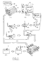
- the essential steps comprise (1) casting metallic engine blocks 10 of a fixed configuration with a plurality of cylinder bores 11, (2) cutting a set of metallic liner inserts 12 from a first extruded tubing 13 (with a given thickness 14) for each of the cylinder bores 11 of a first engine block, and following steps (3)-(4) involving cleaning of the liner inserts, exposing fresh metal, undercoating and topcoating while rotating the liners, and then (5) implanting the set of coated liner inserts 12 into cylinder bores 11 of the first engine block, and (6) optionally honing the interior coating and (7) optionally coating the honed interior coating with an abradable coating that can effect essentially zero clearance.
- a set of second liner inserts 15 is cut from extruded tubing 16 (having a different wall thickness 17) for defining inserts for each of the cylinder bores 11 of another engine block of the same fixed configuration, and again following steps (3) through (7) as above to coat and install such second liners 15 in the second engine block.
- the use of differing insert wall thicknesses to achieve a variation in engine displacement volume for a fixed designed block, is unique in a first aspect.
- the displacement volume ( ⁇ D 2 /4 • L), for a circular cylindrical bore, can be significantly affected by controlling insert wall thickness.
- the displacement volume 20 will be about 3.2 litres for a V-8 engine and 2.4 litres for a V-6.
- the extruded insert 15 wall thickness 17 is 10mm
- the insert length (18) is the same
- the displacement volume 21 will be about 2.1 litres for a V-8 and about 1.6 litres for a V-6.
- the variation in displacement volume from 2.1 litres to 3.2 litres permits a V-8 type engine to have a wide range of designed horsepower. This permits significant design flexibility without changing any design aspect of the dedicated engine block except the thickness of the insert wall. It should be noted that radii and wall thicknesses are exaggerated in figures 2A-2D to illustrate the change point.
- Such displacement flexibility can be further enhanced by casting the fixed configuration block with an ovoid type cross-section 22 for the cylinder bores.
- the cross-section 22 would essentially consist of two half circles 23,24 (consistent with a normal circular bore) spaced apart by a pair of small incremental straight sides 25,56, thereby forming a rectangle 27 between the two half circles.
- Such spacing creates a major axis 28 and a minor axis 29 for the cross-sectional ovoid. If the ratio of the major axis to the minor axis is controlled within the range of 1.0 to 1.35 for the cylinder bore, the liner insert can be varied in wall thickness in another way.
- the extruded tubing must have an outside surface complementary to the cylinder bore ovoid shape but the interior surface can range from a circular shape to progressive ovoids in cross-section.
- the critical control thickness of the insert will be that adjacent the straight sides 26,25. When the thickness of this critical part is changed, the displacement volume will be changed, but to a greater degree because leverage can be obtained by making the insert interior more ovoid.
- the displacement volume for the interior of a liner insert 30 with a circular interior 3 will be ⁇ D 3 4 + .2D 3 , where D is the internal diameter of the round surface. If the wall thickness at 31,32 is about 1.0mm, D is about 8cm, and the liner length is 8cm, then the displacement volume 36 will be as above, 3.2 litres for a V-8 and 2.4 litres for a V-6.
- the displacement volume 35 for a V-8 engine will be 4.0 litres and 3.0 litres for a V-6, considerably greater than the 3.2 and 2.4 litres of a circular bore above. If the wall thickness at 37,38 is increased to 10mm, then the displacement volume will be reduced to 3.1 and 2.2 litres, respectively.
- the casting of the engine block can be by sand moulding (such as in a mould 40 having appropriate gating to permit uniform metal flow and solidification without undue porosity), shell moulding, permanent or semi-permanent moulding, die casting, or other commercially acceptable casting technique.
- Sand moulding is advantageous because it provides good product definition with optimum quality and economy for large scale production.
- the casting process should be controlled in a manner to ensure proper preparation of the metallic surfaces for the eventual coating system by properly controlling the temperature of the molten metal, design of appropriate gating, and by anchoring the sand core so that the bore centres and the cast block will be centre to centre within ⁇ 200 microns of the specified dimension.
- Each of the liners is sectioned from a metal (such as aluminum) that is essentially the same as the block (such as aluminum).
- the liners are sectioned from extruded tubing by high pressure water cutting, such as at 41 or by a process that cuts rapidly without inducing distortion (examples are laser cutting and high speed diamond cutting; but high pressure water cutting is preferred).
- the tubing desirably has a chemistry of commercial duraluminium 6060 alloy.
- the tubing has a wall thickness 14 or 17 accurate to 35 microns ⁇ 15 microns over the length of the liner, on its internal/external surfaces and is straight within ⁇ 15 microns per foot, with diameters (for curved portions) concentric to within ⁇ 15 microns over the length 18 of the liner insert.
- the cut tubing 12 or 15 need not be precision machined to centre its interior surface and assure its concentricity with respect to its intended axis 43 or axes 44,45 in the case of the ovoid; however, the interior surface may be rough honed to remove about 100 microns of aluminum in an effort to present a surface more amenable to receiving a coating.
- the exterior surface 46 may be smoothed by honing to remove about 20 microns of metal therefrom for the purpose of uniformity, accurate mating with the block bore surface to permit a uniform heat path, and for producing a smoother finish with concentricity required as above.
- the internal surface 47 of the prepared liner 12 or 15 is preferably cleansed by degreasing (see 48 of figure 1), washing by spraying 49 (see 50) and thence air jet drying (see 51).
- Degreasing is sometimes necessary if the liner by its extrusion technique tends to leave a residue.
- Degreasing may be carried out without OSHA approved solvents, such as chloromethane or ethylene chloride, followed by rinsing with isopropyl alcohol.
- the degreasing may be carried out in a vapour form such as in a chamber having a solvent heated to a temperature of 50°F over its boiling point, but with a cooler upper chamber to permit condensation.
- the cleansed liner insert 12 or 15 (having a micro inner surface 47 appearing as shown in Figure 3) is then fixtured to revolve about a horizontal axis 52.
- the internal surface 47 may first be treated to expose fresh metal, such as by grit (shot) blasting using non-friable aluminum oxide 53 (40 grit size) applied with 15-25 psi pressure (see 54).
- fresh metal may be exposed by electric discharge erosion, plasma etching with FCFC 8 or halogenated hydrocarbons or vapour grit blast (150-325 mesh). With respect to grit blasting, oil-free high pressure air may then be used to eliminate any remnants of the grit.
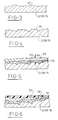
- microsurface 47 appearance is changed by grit blasting, as shown in Figure 4, to have a rougher contour 55. This step may not be necessary if the tube interior surface is alternatively freshly honed to a desirable texture. In the latter case, minimum time is permitted to elapse before applying the coating.
- a bonding undercoat 56 is desirable applied by thermalspraying 57 (such as by wire arc or by plasma spray).
- the material 58 of the bond coating is advantageously nickel aluminide, manganese aluminide or iron aluminide (aluminum being present in an amount of about 2-6% by weight).
- the metals are in a free state in the powder and react in the plasma or arc to produce an exothermic reaction resulting in the formation of inter-metallic compounds. These particles of the inter-metallic compounds adhere to the aluminum substrate surface upon impact of the spray 61 resulting in excellent bond strength.
- the particles of the bond coat adhere to the aluminum substrate as a result of the high heat of reaction and the energy of impact to present an attractive surface to the topcoat 59 having a highly granular and irregular surface.
- the undercoat 56 can be eliminated provided the composition of the topcoat 59 is modified to improve bond strength.
- the topcoat 59 is then applied by plasma spraying (see 60).
- a plasma can be created by an electric arc struck between a tungsten cathode and a nozzle shape copper anode, which partially ionises molecules of argon and hydrogen gas passed into the chamber of the spray gun by injecting powders 62 axially into the plasma flame. Particles can reach speeds of 600 meters per second before impacting onto a target.
- the inert gas such as argon with hydrogen, is propelled into the gun at a pressure of about 5 to 150 psi, and at a temperature of about 30°-100°F.
- the powder feed supply 62 consists of a metalised powder which at least has a shell of metal that is softened (or is an agglomerated composite of fine metal carrying a solid lubricant) during the very quick transient temperature heating in the plasma stream.
- the skin-softened particles impact on the target surface as the result of the high velocity spray pattern.
- a major portion of the particles usually have an average particle size in the range of -200 + 325.
- the plasma spray 63 can deposit a coating thickness 64 (see Figure 5) of about 75-200 microns in one pass along the length of the liner insert. Concurrent with the plasma spraying of the internal surface 47, the outside surface 46 of the liner inserts may be cooled with compressed air thereby ensuring an absence of distortion or at least limiting maximum distortion of the wall of the liner to about 15 microns.
- the topcoat 59 powder particles can be, for purposes of this invention, any one of (i) iron or steel particles having an oxide with a low coefficient of dry friction of 0.2-0.35 or less as shown in figure 7, (ii) a non-oxide steel or other metal which is mixed with solid lubricant selected from the group consisting of graphite, BN, or eutectics of LiF/NaF 2 or CaF 2 /NaF 2 as shown in figure 8; and (iii) metal encapsulated solid lubricants of the type described in (ii).
- the chemistry of these powders all should present a dry coefficient of friction in the coated form which is less than .4 and present a high degree of flowability for purposes of being injected into the plasma spray gun.
- the steel may be of a martensitic type having an alloy content by weight of about .1-.4 carbon, 1-8 manganese, 1-15% chromium, 1-5% nickel and the remainder predominantly iron.
- the stainless steel particles should preferably contain less than .5 carbon by weight and more than .5% by weight chromium and 2-4% manganese to be air hardenable upon exposure to air in the deposited form. The hardness of these particles increases from about R C 45 to 55 as a result of air hardening.
- the average particle size should not be outside the range of 10-40 microns; if the particle size is lower than 10 microns, it will be too fine and will be difficult to process. If the particle size is greater, such as 60 microns, it will be too course and will not carry an adequate amount of solid lubricant in the composite.
- the topcoat solid lubricant particles preferably consist of both boron nitride 66 (which has an oil attracting characteristic and is relatively more expensive) and a eutectic 67 of calcium fluoride and lithium fluoride (which eutectic does, to a moderate extent, has an oil attracting characteristic, but is easier to plasma spray because of its lower melting temperature).
- a eutectic means the lowest combination of melting temperatures of the mixed ingredients.
- the boron nitride is desirably less than 3% by weight (15% by volume) of the composite.
- the proportion of LiF is not limited to the eutectic but can range from 10-90% by weight of the solid lubricant.
- the solid lubricants should have a particle size of about 10-40 microns. If the solid lubricants are combined with nickel, the nickel encapsulated solid lubricant 68 may have solid lubricant in an amount of 30% by volume of the nickel boron nitride. The boron nitride is desirably present in an amount of 25-100% by weight of the solid lubricants.
- a binder may be utilised to hold the mixed particles together and should be present in the powder supply 62 in an amount of about .5-4% by weight and optimally at about .5%.
- the binder is evaporated by thermalspraying.
- the proportion of stainless steel particles to solid lubricant particles can be 60/40 to 85/15, but should preferably be about 75/25.
- the agglomerated particles should have an average particle size in the range of 40-150 microns.
- the oxygen must be .1-.45% by weight in the oxide form.
- the particles should preferably consist essentially of a steel grain 69 having a composition consisting essentially of by weight of the material, carbon .15-.85%, an air hardening agent selected from manganese and nickel in a amount of .1-6.5%, oxygen in an amount of .1-.45% and the remainder essentially iron.
- Each grain has a controlled size and fused shape which is flattened as a result of impact upon deposition leaving desirable micropores 71.
- the honed surface 72 of the coating will expose such micropores.
- the critical aspect of the steel grains is that it leaves at least 90% by weight of the iron, that is combined with oxygen, in the FeO form 70 only.
- the steel particle have a hardness of about R c 20-40, the particle size of about 10-110 microns and a shape generally of irregular granular configuration.
- the coefficient of friction for the FeO form 70 of iron oxide is about .2. This compares to a dry coefficient of friction of .4 for Fe 3 O 4 , of about .45 to .6 for Fe 2 O 3 , 0.3 for nickel, 0.6 for NiAlSi, 0.3-0.4 for Cr 2 O 3 , and 0.3-0.4 for chromium. It is desirable to produce such oxided steel particle by comminuting a stream of molten sponge iron. Due to the exclusion of air or other oxygen contaminants, the only source of oxygen to unite with the iron in the molten stream is in the steam or water jet used to comminute the stream itself. This limited access to oxygen forces the iron to combine as FeO and not as Fe 2 O 3 . The reduction of water release H 2 and the hydrogen adds to the non-oxidising atmosphere in the atomisation chamber.
- an overcoat 73 may be applied over the topcoat 59, the former being an abradable coating comprising solid lubricants in an emulsion or polymer base.
- This overcoat permits the total thickness of the coating to present essentially zero clearance for the piston to bore wall fit.
- the liner inserts 12 or 15 may be implanted by shrink fitting into a slightly undersized cylinder bore 11, or the liner inserts may be cast in place when the block is cast itself.
- the liner inserts are prepared and coated as detailed earlier, and placed on cylinder bore cores in the mould.
- the liner inserts are heated prior to casting such as by induction heating, and the outer surface of the liners may be textured to affect greater locking between the molten metal and the liner outside diameter.
- the cylinder bore centres should be true to the final machined bore centres to within 100 microns, to thereby avoid the cost of applying excess coating.
- the liners are cooled to a temperature of about -100°C by use of isopropyl alcohol and dry ice. While the engine block is maintained at about ambient temperature, the frozen liners, along with their coatings, are placed into the bores 11 and allowed to heat up to room temperature whereby the outer surface of the bore wall comes into intimate interfering contact with the inserts as a result of expansion. Alternatively, the block could be heated to about 300°F and the liner inserts, held at room temperature, dropped in place.
- the tubing that is used to make the liners should have an outside diameter that is about 35 microns ( ⁇ 15 microns) in excess of the bore wall internal diameter of the engine block while they are both at ambient temperatures. It is advantageous to coat the exterior surface 46 of the liner inserts with a very thin coating of copper flake and a polymer, such coating 74 having a thickness of about 5 microns. Thus, when the liner is forced into interference fit with the aluminum block cylinder wall, a very superior thermally conductive bond therebetween takes place.
- the coated interior surface 47 may be plateau honed 75 (see step 6 of figure 1) in increments of about 100, 300, and 600 grit to bring the exposed coated surface to a predetermined surface finish.
- the liner inserts may protrude approximately 10 to 25 microns over the face surface of the block; such protrusion is machined 74 (deck facing) to a common plane required for sealing the engine gasket.
- a polymer based solid film lubricant overcoating 73 is applied by a brush or tool 76 onto a prehoned surface (see step 7). If the total coating system is applied in a very thin thickness to a precision machined bore surface, then honing may not be necessary.
- the common sized cylindrical bores 11 can be circular in cross-section as is conventional and as shown in figure 1. the design control is then focused in the extruded tubing wall thickness which will be uniformly thick and is selected from 1-15mm; both the interior and exterior surfaces of such tubing would be circular in cross-section. This permits the change in cylinder volume displacement to be as much as 100% for a V-8 engine.
- the common sized cylindrical bores may be shaped in cross-section as an ovoid. Ovoid is defined herein to mean a shape comprising two half circles separated by essentially a rectangle bonded by essentially straight walls (see figure 11). The ovoid bore in the block may be cast to shape.
- the exterior or interior of the extruded tubing if shaped as an ovoid, can be done by controlling the extrusion die.
- the insert can have an exterior ovoid surface and a circular interior surface, but such interior surface can be selected from circular to an ovoid with small straight sides, to an ovoid with large straight sides, to an ovoid with large straight sides more complementary to the exterior surface.
- piston and piston ring assembly is as shown in figures 10, 12, 13A and 13B.
- the piston assembly 80 provides for compression rings 81,82 matingly superimposed one upon another in a single stepped groove 83 with the split ends of each of the compression rings out of superimposed axial alignment.
- a conventional oil control ring 84 may be used in groove 85 spaced a distance from the single groove.
- the compression rings may be made of conventional iron or steel or lighter metals such as aluminum.
- the surfaces of the groove 83 as well as the non-mating surfaces of the pair of compression rings are coated with a solid film lubricant 86 in a coating thickness usually of about 10 microns or less.
- the groove is stepped at 87 into upper and lower spaces 80,89 with the upper space 88 having the greater groove depth.
- the step 87 may be formed with mutually perpendicular surfaces.
- the groove as a whole can have a much greater height than allowed by prior art grooves (the groove height has heretofore been dictated by the need to keep rings thin to control ring tension).
- the stepped groove of increased height can have an aspect ratio (depth to height) which is less than 10 and preferably less than 5.
- Each ring 81,82 resides essentially in a different one of the spaces with the uppermost ring 81 having its bottom surface 90 engageable with both the top surface 87A of the groove step and the top surface 91 of the lowermost ring 82.
- the uncoated mating surfaces 90 and 91 should have a coefficient of friction of .12-.15 or more.
- a leak path #1 which would follow behind the rings and underneath either of the rings is closed off under all operating conditions.
- a leak path #2 which would follow between the outer circumference of the rings and the bore wall 11 is closed or becomes essentially zero clearance therebetween.
- a leak path #3 through the rings between the split ends thereof is reduced to a negligible amount because of the super
- the combined features operate to eliminate blow-by (through leak paths #1, #2 and #3) in this manner: the combustion gas pressure presses down on the top surface of the upper compression ring 81 forcing the pair of compression rings 81,82 to contact each other along their mating uncoated surfaces 90,91.
- the absence of oil between these mating surfaces and the normally high friction coefficient (i.e. .12-.15) of such surfaces will ensure movement of the pair of rings as a unit or couple.
- the upper compression ring 81 will act as an effective seal.
- the lower compression ring is designed to be essentially an oil film scrapper (has barrel shaped outer edge contour) during the downward motion of the piston and contributes little or no friction.
- the split end pairs 94,95 and 96-97 of the respective compression rings are out of superimposed alignment and may be referred to hereafter as being overlapped.
- Each pair of split ends is dovetailed (or overlapped) in a circumferential direction, that is, the split end pairs are not in superimposed alignment. This feature is important because of the tight union maintained between the upper and lower compression rings resulting from the force of gas pressure; the leakage path for combustion gases (to migrate through any gap or spacing between the split ends) is eliminated due to this dual overlapping condition.
- the dovetailing construction creates overlapping tongues such as 98 and 99 contoured radially to have a notch creating a such tongues; the tongues are overlapped in a radial direction within a ring, but overlapped circumferentially between rings. Because the superimposed rings block any direct path through the rings, leak path #3 is again essentially eliminated.
- honing When any ovoid interior surfaces are coated, honing must be controlled to assure concentricity of the coating on the curvilinear portions with the operating axes of the engine.
- Such operating axes include the crankshaft axis of revolution 100 and the connecting rod pin axis 101 (parallel to the crankshaft axis. It is important the honing axis be perpendicular to the crankshaft axis so that the minor axis of the ovoid will be parallel to axes 100 and 101.
- volume displacement variation is achieved by liner wall thickness variation and/or interior cross-sectional shape. This will necessitate a change in piston cross-section to accommodate such variation in volumetric shape.
Landscapes
- Engineering & Computer Science (AREA)
- Chemical & Material Sciences (AREA)
- Combustion & Propulsion (AREA)
- Mechanical Engineering (AREA)
- General Engineering & Computer Science (AREA)
- Cylinder Crankcases Of Internal Combustion Engines (AREA)
- Shafts, Cranks, Connecting Bars, And Related Bearings (AREA)
Applications Claiming Priority (2)
| Application Number | Priority Date | Filing Date | Title |
|---|---|---|---|
| US08/407,524 US5566450A (en) | 1995-03-16 | 1995-03-16 | Flexibly making engine block assemblies |
| US407524 | 1995-03-16 |
Publications (2)
| Publication Number | Publication Date |
|---|---|
| EP0732493A1 true EP0732493A1 (fr) | 1996-09-18 |
| EP0732493B1 EP0732493B1 (fr) | 1999-05-19 |
Family
ID=23612434
Family Applications (1)
| Application Number | Title | Priority Date | Filing Date |
|---|---|---|---|
| EP96300914A Expired - Lifetime EP0732493B1 (fr) | 1995-03-16 | 1996-02-09 | Méthode flexible pour l'assemblage des blocs moteurs |
Country Status (5)
| Country | Link |
|---|---|
| US (1) | US5566450A (fr) |
| EP (1) | EP0732493B1 (fr) |
| CA (1) | CA2168916A1 (fr) |
| DE (1) | DE69602481T2 (fr) |
| ES (1) | ES2132842T3 (fr) |
Cited By (4)
| Publication number | Priority date | Publication date | Assignee | Title |
|---|---|---|---|---|
| EP0790397A1 (fr) * | 1996-02-17 | 1997-08-20 | Federal-Mogul Burscheid GmbH | Chemise de cylindre pour moteur à combustion interne et procédé de fabrication |
| EP0896146A3 (fr) * | 1997-08-06 | 1999-08-18 | DEUTZ Aktiengesellschaft | Culasse pour un carter-moteur à plusieurs alésages |
| DE19831046A1 (de) * | 1998-07-13 | 2000-01-20 | Dragan Popov | Verfahren zum Herstellen eines Referenzmotors und Referenzmotor |
| FR2971319A1 (fr) * | 2011-02-03 | 2012-08-10 | Peugeot Citroen Automobiles Sa | Procede de revetement d'un fut de carter cylindres sur chemise inseree a la coulee et vehicule correspondant |
Families Citing this family (20)
| Publication number | Priority date | Publication date | Assignee | Title |
|---|---|---|---|---|
| US20030012985A1 (en) | 1998-08-03 | 2003-01-16 | Mcalister Roy E. | Pressure energy conversion systems |
| US5671532A (en) * | 1994-12-09 | 1997-09-30 | Ford Global Technologies, Inc. | Method of making an engine block using coated cylinder bore liners |
| US5842109A (en) * | 1996-07-11 | 1998-11-24 | Ford Global Technologies, Inc. | Method for producing powder metal cylinder bore liners |
| KR100467112B1 (ko) * | 1999-10-29 | 2005-01-24 | 닛폰 피스톤 린구 가부시키가이샤 | 내연기관의 실린더 라이너와 피스톤 링의 조합 |
| US6449842B1 (en) * | 2000-09-28 | 2002-09-17 | Total Seal, Inc. | Powder for piston-ring installation |
| US6560867B2 (en) * | 2001-07-10 | 2003-05-13 | Eaton Corporation | Modular valvetrain and cylinder head structure |
| US6588408B2 (en) | 2001-09-18 | 2003-07-08 | Federal-Mogul World Wide, Inc. | Cylinder liner for diesel engines with EGR and method of manufacture |
| US6688867B2 (en) * | 2001-10-04 | 2004-02-10 | Eaton Corporation | Rotary blower with an abradable coating |
| US20040244758A1 (en) * | 2003-06-06 | 2004-12-09 | Cummins Inc. | Method for increasing the displacement of an internal combustion engine and engine having increased displacement thereby |
| DE102011012507B4 (de) * | 2011-02-25 | 2014-11-27 | Ks Kolbenschmidt Gmbh | Funktionsoptimierte Gestaltung eines Ringelements für Zylinder einer Brennkraftmaschine |
| US9377105B2 (en) * | 2013-03-12 | 2016-06-28 | Mcalister Technologies, Llc | Insert kits for multi-stage compressors and associated systems, processes and methods |
| US8838367B1 (en) | 2013-03-12 | 2014-09-16 | Mcalister Technologies, Llc | Rotational sensor and controller |
| US9255560B2 (en) | 2013-03-15 | 2016-02-09 | Mcalister Technologies, Llc | Regenerative intensifier and associated systems and methods |
| WO2014144581A1 (fr) | 2013-03-15 | 2014-09-18 | Mcalister Technologies, Llc | Moteur à combustion interne et systèmes et procédés associés |
| DE102013211324A1 (de) * | 2013-06-17 | 2014-12-18 | Dürr Ecoclean GmbH | Verfahren und Anlage zum Vorbereiten und Beschichten einer Werkstückoberfläche |
| US9856817B2 (en) * | 2015-03-31 | 2018-01-02 | Harley-Davidson Motor Company Group, LLC | Bolt-on cylinder kit and method for increasing the displacement of an engine |
| US10132267B2 (en) * | 2015-12-17 | 2018-11-20 | Ford Global Technologies, Llc | Coated bore aluminum cylinder liner for aluminum cast blocks |
| DE102016101709B4 (de) * | 2016-02-01 | 2018-12-27 | Federal-Mogul Burscheid Gmbh | Verfahren zur Herstellung eines Zylinderkurbelgehäuses mit Zylinderlaufbuchse |
| US10066577B2 (en) | 2016-02-29 | 2018-09-04 | Ford Global Technologies, Llc | Extruded cylinder liner |
| DK179001B1 (en) | 2016-03-09 | 2017-08-07 | Man Diesel & Turbo Filial Af Man Diesel & Turbo Se Tyskland | Engine device of an internal combustion engine |
Citations (5)
| Publication number | Priority date | Publication date | Assignee | Title |
|---|---|---|---|---|
| FR605541A (fr) * | 1925-10-19 | 1926-05-28 | Manchon réduisant la cylindrée et diminution de la chambre de compression dans les moteurs à explosions pour économiser l'essence | |
| GB281347A (en) * | 1926-06-03 | 1927-12-05 | David Lewis Lipman | Methods of and means for reducing cylinder capacity in internal combustion engines and the like |
| GB2021236A (en) * | 1978-05-23 | 1979-11-28 | Terenzi A | Cylinder liners |
| WO1994011612A1 (fr) * | 1992-11-10 | 1994-05-26 | Robert Wilhelm Heiliger | Procede de fabrication d'une unite piston-cylindre et unite piston-cylindre realisee selon ledit procede |
| EP0611878A1 (fr) * | 1993-02-03 | 1994-08-24 | AVL Gesellschaft für Verbrennungskraftmaschinen und Messtechnik mbH.Prof.Dr.Dr.h.c. Hans List | Méthode de fabrication d'un bloc cylindres à plusieurs parties |
Family Cites Families (15)
| Publication number | Priority date | Publication date | Assignee | Title |
|---|---|---|---|---|
| US991404A (en) * | 1909-11-10 | 1911-05-02 | Lyman Woodworth | Gas or combustion engine. |
| US1347476A (en) * | 1915-03-29 | 1920-07-20 | Aluminum Castings Company | Process of making cylinders for internal-combustion engines |
| US3620137A (en) * | 1969-10-06 | 1971-11-16 | Ramsey Corp | Piston sleeve |
| JPS5341621A (en) * | 1976-09-27 | 1978-04-15 | Honda Motor Co Ltd | Cylinders for internal combustion engine |
| JPS55164745A (en) * | 1979-05-22 | 1980-12-22 | Nippon Piston Ring Co Ltd | Cylinder and cylinder liner |
| DE3033475A1 (de) * | 1979-09-07 | 1981-04-09 | Baker, Archibald John, Stephan, Childrey, Wantage,Oxon | Verfahren zur herstellung einer duennen zylinderauskleidung |
| US4495907A (en) * | 1983-01-18 | 1985-01-29 | Cummins Engine Company, Inc. | Combustion chamber components for internal combustion engines |
| JPS6043150A (ja) * | 1983-08-19 | 1985-03-07 | Komatsu Ltd | エンジン |
| JPH071023B2 (ja) * | 1988-10-14 | 1995-01-11 | いすゞ自動車株式会社 | 内燃機関用シリンダライナー |
| US5255433A (en) * | 1991-04-10 | 1993-10-26 | Alcan International Limited | Engine block cylinder liners made of aluminum alloy composites |
| US5291862A (en) * | 1992-01-09 | 1994-03-08 | Honda Giken Kogyo Kabushiki Kaisha | Cylinder sleeve assembly used in cylinder block for multi-cylinder internal combustion engine, and forming mold for use in production of sand mold for casting the same |
| US5320158A (en) * | 1993-01-15 | 1994-06-14 | Ford Motor Company | Method for manufacturing engine block having recessed cylinder bore liners |
| US5302450A (en) * | 1993-07-06 | 1994-04-12 | Ford Motor Company | Metal encapsulated solid lubricant coating system |
| US5363821A (en) * | 1993-07-06 | 1994-11-15 | Ford Motor Company | Thermoset polymer/solid lubricant coating system |
| US5419037A (en) * | 1994-05-20 | 1995-05-30 | Outboard Marine Corporation | Method of inserting, boring, and honing a cylinder bore liner |
-
1995
- 1995-03-16 US US08/407,524 patent/US5566450A/en not_active Expired - Lifetime
-
1996
- 1996-02-06 CA CA002168916A patent/CA2168916A1/fr not_active Abandoned
- 1996-02-09 DE DE69602481T patent/DE69602481T2/de not_active Expired - Fee Related
- 1996-02-09 ES ES96300914T patent/ES2132842T3/es not_active Expired - Lifetime
- 1996-02-09 EP EP96300914A patent/EP0732493B1/fr not_active Expired - Lifetime
Patent Citations (5)
| Publication number | Priority date | Publication date | Assignee | Title |
|---|---|---|---|---|
| FR605541A (fr) * | 1925-10-19 | 1926-05-28 | Manchon réduisant la cylindrée et diminution de la chambre de compression dans les moteurs à explosions pour économiser l'essence | |
| GB281347A (en) * | 1926-06-03 | 1927-12-05 | David Lewis Lipman | Methods of and means for reducing cylinder capacity in internal combustion engines and the like |
| GB2021236A (en) * | 1978-05-23 | 1979-11-28 | Terenzi A | Cylinder liners |
| WO1994011612A1 (fr) * | 1992-11-10 | 1994-05-26 | Robert Wilhelm Heiliger | Procede de fabrication d'une unite piston-cylindre et unite piston-cylindre realisee selon ledit procede |
| EP0611878A1 (fr) * | 1993-02-03 | 1994-08-24 | AVL Gesellschaft für Verbrennungskraftmaschinen und Messtechnik mbH.Prof.Dr.Dr.h.c. Hans List | Méthode de fabrication d'un bloc cylindres à plusieurs parties |
Cited By (5)
| Publication number | Priority date | Publication date | Assignee | Title |
|---|---|---|---|---|
| EP0790397A1 (fr) * | 1996-02-17 | 1997-08-20 | Federal-Mogul Burscheid GmbH | Chemise de cylindre pour moteur à combustion interne et procédé de fabrication |
| US5829405A (en) * | 1996-02-17 | 1998-11-03 | Ae Goetze Gmbh | Engine cylinder liner and method of making the same |
| EP0896146A3 (fr) * | 1997-08-06 | 1999-08-18 | DEUTZ Aktiengesellschaft | Culasse pour un carter-moteur à plusieurs alésages |
| DE19831046A1 (de) * | 1998-07-13 | 2000-01-20 | Dragan Popov | Verfahren zum Herstellen eines Referenzmotors und Referenzmotor |
| FR2971319A1 (fr) * | 2011-02-03 | 2012-08-10 | Peugeot Citroen Automobiles Sa | Procede de revetement d'un fut de carter cylindres sur chemise inseree a la coulee et vehicule correspondant |
Also Published As
| Publication number | Publication date |
|---|---|
| DE69602481T2 (de) | 1999-10-21 |
| DE69602481D1 (de) | 1999-06-24 |
| CA2168916A1 (fr) | 1996-09-17 |
| EP0732493B1 (fr) | 1999-05-19 |
| US5566450A (en) | 1996-10-22 |
| ES2132842T3 (es) | 1999-08-16 |
Similar Documents
| Publication | Publication Date | Title |
|---|---|---|
| EP0732493B1 (fr) | Méthode flexible pour l'assemblage des blocs moteurs | |
| EP0716156B1 (fr) | Bloc moteur avec chemises de cylindre revêtues | |
| US6513238B1 (en) | Connecting rod with thermally sprayed bearing layer | |
| DK174241B1 (da) | Cylinderelement, såsom en cylinderforing, et stempel, et stempelskørt eller en stempelring, i en forbrændingsmotor af dieseltypen samt en stempelring til en sådan motor. | |
| US5363821A (en) | Thermoset polymer/solid lubricant coating system | |
| US6095107A (en) | Method of producing a slide surface on a light metal alloy | |
| US10746128B2 (en) | Cylinder bore having variable coating | |
| US6044820A (en) | Method of providing a cylinder bore liner in an internal combustion engine | |
| US6379754B1 (en) | Method for thermal coating of bearing layers | |
| JPH08246943A (ja) | シリンダ孔壁がコーティングされたエンジンブロックを製造する方法 | |
| US4323257A (en) | Piston ring with a Cr-C-Fe inlaid ring in its outer surface, and a method of making it | |
| US3920360A (en) | Aluminum-iron composite rotor housing for a rotary combustion engine and method of making the same | |
| JPH0419345A (ja) | 内燃機関用のシリンダブロック、およびそれを製造する方法 | |
| US5598818A (en) | Method of providing a cylinder bore liner in an internal combustion engine | |
| US3981688A (en) | Coating for rotary engine rotor housings and method of making | |
| US6329022B1 (en) | Connecting rod with a high strength bearing layer | |
| US10180114B1 (en) | Selective surface porosity for cylinder bore liners | |
| US6367151B1 (en) | Connecting rod with thermally sprayed bearing layer | |
| US5655955A (en) | Method and tool for improving the structure of the inner faces of working chambers of machines and motors | |
| AU627583B2 (en) | Manufacture of poppet valves by spray deposition | |
| CN109881138A (zh) | 一种保护涂层施工工艺 | |
| JPH08246944A (ja) | 内燃機関のシリンダおよびその製造方法 | |
| CN109882306A (zh) | 一种用于缸体内壁的改性结构 | |
| DK172547B1 (da) | Stempelringe og/eller stempel i en forbrændingsmotor af dieseltypen samt fremgangsmåde til indkøring af en dieselmotor | |
| JPS6240425B2 (fr) |
Legal Events
| Date | Code | Title | Description |
|---|---|---|---|
| PUAI | Public reference made under article 153(3) epc to a published international application that has entered the european phase |
Free format text: ORIGINAL CODE: 0009012 |
|
| AK | Designated contracting states |
Kind code of ref document: A1 Designated state(s): DE ES GB |
|
| 17P | Request for examination filed |
Effective date: 19961111 |
|
| GRAG | Despatch of communication of intention to grant |
Free format text: ORIGINAL CODE: EPIDOS AGRA |
|
| 17Q | First examination report despatched |
Effective date: 19980323 |
|
| GRAG | Despatch of communication of intention to grant |
Free format text: ORIGINAL CODE: EPIDOS AGRA |
|
| GRAH | Despatch of communication of intention to grant a patent |
Free format text: ORIGINAL CODE: EPIDOS IGRA |
|
| GRAH | Despatch of communication of intention to grant a patent |
Free format text: ORIGINAL CODE: EPIDOS IGRA |
|
| GRAH | Despatch of communication of intention to grant a patent |
Free format text: ORIGINAL CODE: EPIDOS IGRA |
|
| GRAA | (expected) grant |
Free format text: ORIGINAL CODE: 0009210 |
|
| AK | Designated contracting states |
Kind code of ref document: B1 Designated state(s): DE ES GB |
|
| REF | Corresponds to: |
Ref document number: 69602481 Country of ref document: DE Date of ref document: 19990624 |
|
| REG | Reference to a national code |
Ref country code: ES Ref legal event code: FG2A Ref document number: 2132842 Country of ref document: ES Kind code of ref document: T3 |
|
| PLBE | No opposition filed within time limit |
Free format text: ORIGINAL CODE: 0009261 |
|
| 26N | No opposition filed | ||
| PGFP | Annual fee paid to national office [announced via postgrant information from national office to epo] |
Ref country code: DE Payment date: 20010205 Year of fee payment: 6 |
|
| PGFP | Annual fee paid to national office [announced via postgrant information from national office to epo] |
Ref country code: GB Payment date: 20010207 Year of fee payment: 6 |
|
| PGFP | Annual fee paid to national office [announced via postgrant information from national office to epo] |
Ref country code: ES Payment date: 20010220 Year of fee payment: 6 |
|
| REG | Reference to a national code |
Ref country code: GB Ref legal event code: IF02 |
|
| PG25 | Lapsed in a contracting state [announced via postgrant information from national office to epo] |
Ref country code: GB Free format text: LAPSE BECAUSE OF NON-PAYMENT OF DUE FEES Effective date: 20020209 |
|
| PG25 | Lapsed in a contracting state [announced via postgrant information from national office to epo] |
Ref country code: ES Free format text: LAPSE BECAUSE OF NON-PAYMENT OF DUE FEES Effective date: 20020211 |
|
| PG25 | Lapsed in a contracting state [announced via postgrant information from national office to epo] |
Ref country code: DE Free format text: LAPSE BECAUSE OF NON-PAYMENT OF DUE FEES Effective date: 20020903 |
|
| GBPC | Gb: european patent ceased through non-payment of renewal fee |
Effective date: 20020209 |
|
| REG | Reference to a national code |
Ref country code: ES Ref legal event code: FD2A Effective date: 20031022 |