EP0732497B1 - Système d'injection de carburant d'un moteur à combustion interne - Google Patents
Système d'injection de carburant d'un moteur à combustion interne Download PDFInfo
- Publication number
- EP0732497B1 EP0732497B1 EP96102751A EP96102751A EP0732497B1 EP 0732497 B1 EP0732497 B1 EP 0732497B1 EP 96102751 A EP96102751 A EP 96102751A EP 96102751 A EP96102751 A EP 96102751A EP 0732497 B1 EP0732497 B1 EP 0732497B1
- Authority
- EP
- European Patent Office
- Prior art keywords
- throttle valve
- passage
- fuel
- injector
- fuel injection
- Prior art date
- Legal status (The legal status is an assumption and is not a legal conclusion. Google has not performed a legal analysis and makes no representation as to the accuracy of the status listed.)
- Expired - Lifetime
Links
- 239000000446 fuel Substances 0.000 title claims description 50
- 238000002347 injection Methods 0.000 title claims description 21
- 239000007924 injection Substances 0.000 title claims description 21
- 238000002485 combustion reaction Methods 0.000 title claims description 9
- 238000011144 upstream manufacturing Methods 0.000 claims description 12
- 230000002093 peripheral effect Effects 0.000 claims description 9
- 239000000203 mixture Substances 0.000 claims description 4
- 238000000889 atomisation Methods 0.000 description 7
- 239000004215 Carbon black (E152) Substances 0.000 description 6
- 229930195733 hydrocarbon Natural products 0.000 description 6
- 150000002430 hydrocarbons Chemical class 0.000 description 6
- 238000000034 method Methods 0.000 description 4
- 230000001737 promoting effect Effects 0.000 description 2
- 239000002828 fuel tank Substances 0.000 description 1
- 239000002245 particle Substances 0.000 description 1
- 230000001105 regulatory effect Effects 0.000 description 1
- XLYOFNOQVPJJNP-UHFFFAOYSA-N water Substances O XLYOFNOQVPJJNP-UHFFFAOYSA-N 0.000 description 1
Images


Classifications
-
- F—MECHANICAL ENGINEERING; LIGHTING; HEATING; WEAPONS; BLASTING
- F02—COMBUSTION ENGINES; HOT-GAS OR COMBUSTION-PRODUCT ENGINE PLANTS
- F02D—CONTROLLING COMBUSTION ENGINES
- F02D9/00—Controlling engines by throttling air or fuel-and-air induction conduits or exhaust conduits
- F02D9/08—Throttle valves specially adapted therefor; Arrangements of such valves in conduits
- F02D9/10—Throttle valves specially adapted therefor; Arrangements of such valves in conduits having pivotally-mounted flaps
- F02D9/1005—Details of the flap
- F02D9/101—Special flap shapes, ribs, bores or the like
-
- F—MECHANICAL ENGINEERING; LIGHTING; HEATING; WEAPONS; BLASTING
- F02—COMBUSTION ENGINES; HOT-GAS OR COMBUSTION-PRODUCT ENGINE PLANTS
- F02B—INTERNAL-COMBUSTION PISTON ENGINES; COMBUSTION ENGINES IN GENERAL
- F02B61/00—Adaptations of engines for driving vehicles or for driving propellers; Combinations of engines with gearing
- F02B61/02—Adaptations of engines for driving vehicles or for driving propellers; Combinations of engines with gearing for driving cycles
-
- F—MECHANICAL ENGINEERING; LIGHTING; HEATING; WEAPONS; BLASTING
- F02—COMBUSTION ENGINES; HOT-GAS OR COMBUSTION-PRODUCT ENGINE PLANTS
- F02M—SUPPLYING COMBUSTION ENGINES IN GENERAL WITH COMBUSTIBLE MIXTURES OR CONSTITUENTS THEREOF
- F02M69/00—Low-pressure fuel-injection apparatus ; Apparatus with both continuous and intermittent injection; Apparatus injecting different types of fuel
- F02M69/04—Injectors peculiar thereto
- F02M69/042—Positioning of injectors with respect to engine, e.g. in the air intake conduit
- F02M69/043—Positioning of injectors with respect to engine, e.g. in the air intake conduit for injecting into the intake conduit upstream of an air throttle valve
Definitions
- the present invention relates to a fuel injection system of an internal combustion engine according to the preamble of claim 1
- the amount of air delivered from an air cleaner to the throttle body is regulated by the tilting angle of the throttle valve and fuel of a proper flow rate is injected through the nozzle at the distal end of the injector, thereby supplying the fuel-air mixture to the combustion chamber of the engine.
- the fuel is injected from the injector by, for example, forcibly feeding the fuel by a pump to the injector and then opening a solenoid valve, which is provided in the injector, for a limited time.
- the particle diameter of injected fuel is relatively large and a method for promoting the atomization of fuel, i.e. an air assist method, by providing small apertures around the nozzle, is sometimes adopted.
- an air assist method i.e. an air assist method, by providing small apertures around the nozzle.
- the injecting angle becomes larger and fuel tends to adhere to the peripheral wall of the passage of the throttle body, possibly leading to an increased flow of the fuel along the peripheral wall or causing the fuel to stagnate in the throttle body. Therefore, the method does not necessarily ensure improvement in combustion.
- the opening degree of the throttle valve is small, it is likely that fuel fails to be fully atomized because of low flow rate and velocity.
- An object of the present invention is to provide a fuel injection system of the type defined in the preamble of claim 1 which is capable of promoting the atomization of fuel to prevent the fuel from flowing along a wall surface of the passage or stagnating in a throttle body even under an idling condition or other conditions of the engine of a vehicle such as motorcycle, where the opening degree of the throttle valve is small, and also capable of effectively reducing residual hydrocarbon (HC) in an exhaust gas.
- HC residual hydrocarbon
- the throttle valve is disposed in the passage in an inclined manner in a fully closed condition thereof so that one end portion of the throttle valve on the injector location side is positioned on a downstream side of the rotational axis thereof and another end portion of the throttle valve is positioned on an upstream side of the rotational axis.
- These one and another end portions of the throttle valves have end faces obliquely cut so as to extend along an inner wall surface of the throttle body forming the passage.
- the through hole is formed so as to extend perpendicularly with respect to a thickness direction of the throttle valve.
- Another injector means is mounted on the peripheral wall of the passage and adapted to inject fuel in the passage at a portion upstream side of the throttle valve with respect to an air flow in the passage.
- the air coming from the upstream side flows in a concentrated manner through the through hole and increases in its speed when the air passes through the throttle valve.
- the through hole is disposed in the position where it nearly accords with the central axis in the injecting direction of the injector when observed from injector location side with respect to the rotational axis of the throttle valve. Therefore, the air which has passed through the throttle valve and which has increased in flowing speed effectively collides with the fuel which has been injected from the injector at the downstream side of the throttle valve.
- Figs. 1 to 4 represent a first embodiment of a fuel injection system 4 of an engine 2 for vehicle, preferably of a motorcycle.
- the engine is a low-pressure injection type having an approximately cylindrical throttle body 6 provided with a passage 6a for supplying a fuel-air mixture to a combustion chamber, an approximately disc-shaped throttle valve 8 which is rotatably journaled to the peripheral wall of the passage 6a and which regulates the amount of air flowing through the passage 6a by the rotation of the throttle valve 8, and an injector 10 mounted on the peripheral wall of the passage 6a and adapted to inject fuel to the passage 6a.
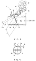
- the injector 10 is disposed on the downstream side observed from the throttle valve 8, which is provided with a through hole 12 opened at both surfaces of the throttle valve 8.
- the through hole 12 is disposed in a position at which the axis of the through hole 12 nearly intersects a central axis 10a of the injector 10 in the injecting direction thereof as viewed from the rear from the injector location side in relation to a rotational axis 8a of the throttle valve 8.
- the motorcycle according to the embodiment is equipped with a head pipe 14 which supports the front wheel capable of being steered, a main frame 16 extending rearward from the head pipe 14 and bent downward, and a down tube 18 extending downward from the head pipe 14 and connected to the bottom end of the main frame 16.
- the engine 2 is rested and fixed on the down tube 18.
- the motorcycle is also provided with a front cowl 20 which covers the front portion of the vehicle.
- the engine 2 is of a parallel four-cylinder, four-stroke-cycle engine, and it is constituted mainly by a crank case 2a rotatably supporting a crankshaft, a cylinder 2b fastened to the front top surface of the crank case 2a, a cylinder head 2c fixed to the top end of the cylinder 2b, and a head cover 2d.
- the front cowl 20 has an intake port 20a opened at the front portion thereof and a duct 20b formed integrally with the cowl 20 and extending from the intake port 20a in the longitudinal direction of the vehicle body.
- the duct 20b is connected to a front end of a hose 22 extending up to the rear top of the crank case 2a.
- the fuel injection system 4 is disposed in the vicinity of the side of the front section of the air cleaner 24.
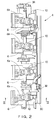
- the engine 2 has four cylinders each provided with the throttle body 6 and the injector 10.
- a delivery pipe 30 which supplies fuel to the respective injectors 10.
- a regulator 32 for adjusting the pressure of fuel to be supplied to the injectors 10 is provided at the left edge (lower side as viewed) of the delivery pipe 30.
- a throttle position sensor 34 is provided beside the throttle body 6 disposed at the rightmost end (upper side as viewed).
- An injector mounting section 6b which opens toward a rear upward direction, is formed near the front portion of the upper wall of each throttle body 6 as shown in Fig. 3.
- Each injector 10 is mounted on the mounting section 6b in such a manner that the distal end thereof is fitted to the mounting section 6b so as to incline downward in a forward direction.
- a suitable inside diameter D of the through hole 12 is considered to be 0.5 to 1.0 mm.
- the major diameter d of the valve refers to an outer diameter of the throttle valve 8 in the direction normal to the rotational axis 8a, and in this embodiment, it is the distance from the end of the top edge surface of the throttle valve 8 on the downstream side to the end of the bottom edge surface on the upstream side.
- the atomization of fuel can be promoted, thereby preventing fuel from flowing along the wall surface of the passage or from stagnating in a throttle body.
- the residual hydrocarbon in an exhaust gas can be reduced.
Landscapes
- Engineering & Computer Science (AREA)
- Chemical & Material Sciences (AREA)
- Combustion & Propulsion (AREA)
- Mechanical Engineering (AREA)
- General Engineering & Computer Science (AREA)
- Control Of Throttle Valves Provided In The Intake System Or In The Exhaust System (AREA)
- Fuel-Injection Apparatus (AREA)
Claims (5)
- Un système d'injection de carburant (4) pour un moteur à combustion interne (2) comprenant :caractérisé en ce que ladite soupape d'étranglement (8) est dotée d'un trou traversant (12) formé à titre de partie sur un côté de montage de l'injecteur par rapport à un axe de rotation (8a) de la soupape d'étranglement (8), de manière qu'un axe du trou traversant (12) coupe sensiblement l'axe central (10a) du nuage de carburant injecté depuis l'injecteur (10), lorsqu'on observe depuis le côté de montage de l'injecteur.un corps d'étranglement (6) à structure cylindrique, comportant un passage (6a) destiné à fournir un mélange air-carburant à une chambre de combustion d'un moteur (2);une soupape d'étranglement discoïde (8), montée dans le passage (6a) de manière à pouvoir tourner dans le but de réguler la quantité d'air s'écoulant à travers le passage (6a); etdes moyens d'injecteur (10) montés dans une paroi périphérique du passage (6a) et adaptés pour injecter les carburants dans une partie du passage (6a) du côté aval de la soupape d'étranglement (8) par rapport à un écoulement d'air se faisant dans le passage (6a), selon le degré d'ouverture de ladite soupape d'étranglement (8);
- Un système d'injection de carburant selon la revendication 1, dans lequel ladite soupape d'étranglement (8) est disposée dans le passage (6a) de façon inclinée à son état complètement fermé, de manière qu'une partie d'extrémité de la soupape d'étranglement (8) du côté du montage de l'injecteur soit positionnée sur un côté aval de son axe de rotation (8a) et qu'une autre partie d'extrémité de la soupape d'étranglement (8) soit positionnée d'un côté amont de l'axe de cotation (8a).
- Un système d'injection de carburant selon la revendication 2, dans lequel lesdites une et autre parties d'extrémité de la soupape d'étranglement (8) ont des faces d'extrémité découpées obliquement pour s'étendre suivant une surface de paroi intérieure du corps d'étranglement formant le passage (6a).
- Un système d'injection de carburant selon la revendication 1, dans lequel ledit trou traversant (12) est formé de manière à s'étendre perpendiculairement par rapport à l'épaisseur de la soupape d'étranglement (8).
- Un système d'injection de carburant selon la revendication 1, dans lequel d'autres moyens d'injecteur (38) sont montés sur la paroi périphérique du passage (6a) et adaptés pour injecter du carburant dans une partie du passage (6a) du côté amont de la soupape d'étranglement (8) par rapport à un écoulement d'air se faisant dans le passage (6a).
Applications Claiming Priority (2)
| Application Number | Priority Date | Filing Date | Title |
|---|---|---|---|
| JP7040822A JPH08232814A (ja) | 1995-02-28 | 1995-02-28 | 内燃機関の燃料噴射装置 |
| JP40822/95 | 1995-02-28 |
Publications (2)
| Publication Number | Publication Date |
|---|---|
| EP0732497A1 EP0732497A1 (fr) | 1996-09-18 |
| EP0732497B1 true EP0732497B1 (fr) | 1998-11-04 |
Family
ID=12591362
Family Applications (1)
| Application Number | Title | Priority Date | Filing Date |
|---|---|---|---|
| EP96102751A Expired - Lifetime EP0732497B1 (fr) | 1995-02-28 | 1996-02-23 | Système d'injection de carburant d'un moteur à combustion interne |
Country Status (4)
| Country | Link |
|---|---|
| US (1) | US5758623A (fr) |
| EP (1) | EP0732497B1 (fr) |
| JP (1) | JPH08232814A (fr) |
| DE (1) | DE69600895T2 (fr) |
Families Citing this family (14)
| Publication number | Priority date | Publication date | Assignee | Title |
|---|---|---|---|---|
| JP3886217B2 (ja) * | 1997-03-27 | 2007-02-28 | ヤマハ発動機株式会社 | 4サイクルエンジンの吸気装置 |
| EP1001160B1 (fr) * | 1998-11-16 | 2003-05-14 | Sanshin Kogyo Kabushiki Kaisha | Moteur à combustion |
| DE19861164A1 (de) * | 1998-12-21 | 2000-07-06 | Anton Kurpas | Einrichtung zur Überwachung und Steuerung einer Brennkraftmaschine |
| JP2000345865A (ja) * | 1999-06-07 | 2000-12-12 | Mitsubishi Electric Corp | 空気流量制御装置用スロットルバルブ |
| JP2004100587A (ja) * | 2002-09-10 | 2004-04-02 | Honda Motor Co Ltd | 内燃機関の燃料噴射装置 |
| JP4101662B2 (ja) * | 2003-01-10 | 2008-06-18 | 本田技研工業株式会社 | 小型車両のエンジン用燃料噴射装置の取付構造 |
| US7296560B2 (en) * | 2005-01-20 | 2007-11-20 | Kubota Corporation | Engine of spark-ignition type |
| JP2006283585A (ja) * | 2005-03-31 | 2006-10-19 | Yamaha Motor Co Ltd | スロットルボディ |
| JP4537933B2 (ja) * | 2005-10-18 | 2010-09-08 | 本田技研工業株式会社 | 吸気制御装置 |
| JP4717586B2 (ja) * | 2005-10-24 | 2011-07-06 | 川崎重工業株式会社 | 燃料噴射式エンジン、及びこれを備える自動二輪車 |
| JP4573771B2 (ja) * | 2005-12-21 | 2010-11-04 | 株式会社ケーヒン | 内燃機関における燃料供給装置 |
| JP4954613B2 (ja) * | 2006-05-26 | 2012-06-20 | 本田技研工業株式会社 | スクータ型車両の吸気装置 |
| TWI319462B (en) * | 2006-05-26 | 2010-01-11 | Honda Motor Co Ltd | Intake system for scooter vehicle |
| JP6489266B2 (ja) * | 2018-04-23 | 2019-03-27 | 株式会社デンソー | バルブユニット |
Family Cites Families (18)
| Publication number | Priority date | Publication date | Assignee | Title |
|---|---|---|---|---|
| GB900386A (en) * | 1958-09-08 | 1962-07-04 | Lexington Prod Ltd | Improvements in or relating to fuel injection for internal combustion engines |
| DE1808632B2 (de) * | 1968-11-13 | 1976-03-11 | Daimler-Benz Ag, 7000 Stuttgart | Einlasskanal einer rotationskolben- einspritzbrennkraftmaschine |
| US4158352A (en) * | 1977-09-30 | 1979-06-19 | The Bendix Corporation | Apparatus for providing additional air to aid starting of I.C. engines |
| JPS6053783B2 (ja) * | 1978-07-17 | 1985-11-27 | ヤマハ発動機株式会社 | 燃料噴射式内燃機関 |
| GB2027488A (en) * | 1978-08-07 | 1980-02-20 | Bendix Corp | Fuel atomization system |
| DE2929195A1 (de) * | 1979-07-19 | 1981-02-05 | Franz Prof Dipl Ing Pischinger | Fuellungsregelung mittels flachschieber |
| JPS56132457A (en) * | 1980-03-19 | 1981-10-16 | Hitachi Ltd | Fuel injector |
| JPS5928038A (ja) * | 1982-08-06 | 1984-02-14 | Yamaha Motor Co Ltd | 燃料噴射式多気筒エンジン |
| US4513720A (en) * | 1982-10-27 | 1985-04-30 | Toyota Jidosha Kabushiki Kaisha | Fuel injection device for motor vehicle |
| JPH0415937Y2 (fr) * | 1985-10-14 | 1992-04-09 | ||
| IT1188541B (it) * | 1986-02-04 | 1988-01-14 | Alfa Romeo Auto Spa | Dispositivo di alimentazione benzina per un motore a c.i. |
| US4768486A (en) * | 1986-12-05 | 1988-09-06 | Honda Giken Kogyo Kabushiki Kaisha | Fuel supply control system for internal combustion engine |
| JPH04193474A (ja) * | 1990-11-27 | 1992-07-13 | Toyo A Tec Kk | 研削盤の砥石修正方法および同装置 |
| JP3003339B2 (ja) * | 1991-12-06 | 2000-01-24 | トヨタ自動車株式会社 | 燃料噴射式内燃機関の吸気装置 |
| JPH0610715A (ja) * | 1992-06-24 | 1994-01-18 | Aisin Seiki Co Ltd | エンジンの吸気制御弁装置 |
| JP2762848B2 (ja) * | 1992-06-30 | 1998-06-04 | 日産自動車株式会社 | 内燃機関の燃料供給装置 |
| US5323753A (en) * | 1992-10-19 | 1994-06-28 | Ford Motor Company | Induction system for an internal combustion engine |
| JPH06173830A (ja) * | 1992-12-09 | 1994-06-21 | Sanshin Ind Co Ltd | 燃料噴射式内燃機関 |
-
1995
- 1995-02-28 JP JP7040822A patent/JPH08232814A/ja active Pending
-
1996
- 1996-02-21 US US08/604,247 patent/US5758623A/en not_active Expired - Fee Related
- 1996-02-23 EP EP96102751A patent/EP0732497B1/fr not_active Expired - Lifetime
- 1996-02-23 DE DE69600895T patent/DE69600895T2/de not_active Expired - Fee Related
Also Published As
| Publication number | Publication date |
|---|---|
| US5758623A (en) | 1998-06-02 |
| JPH08232814A (ja) | 1996-09-10 |
| DE69600895T2 (de) | 1999-04-01 |
| EP0732497A1 (fr) | 1996-09-18 |
| DE69600895D1 (de) | 1998-12-10 |
Similar Documents
| Publication | Publication Date | Title |
|---|---|---|
| EP0732497B1 (fr) | Système d'injection de carburant d'un moteur à combustion interne | |
| JPH0452391B2 (fr) | ||
| JP3690824B2 (ja) | 内燃機関の燃料噴射装置 | |
| KR100359702B1 (ko) | 백본형 자동이륜차의 연료분사 장치 | |
| JPH0413556B2 (fr) | ||
| EP0791743A4 (fr) | Dispositif de reglage de carburant evapore dans un moteur a combustion interne | |
| EP0548160A1 (fr) | Dispositif additionnel d'alimentation en air pour moteur a combustion | |
| JPS6215490Y2 (fr) | ||
| CN105339649B (zh) | 鞍乘型车辆的进气腔室 | |
| JPH09166064A (ja) | 内燃機関の吸気装置 | |
| JPH0882271A (ja) | 流体噴射ノズル及びそれを用いた電磁式燃料噴射弁 | |
| JP3724184B2 (ja) | 燃料噴射装置 | |
| JP2906895B2 (ja) | 内燃機関の燃料供給装置 | |
| EP1073841B1 (fr) | Grille de prise d'air pour injecteur de carburant a assistance pneumatique | |
| JPS5810154A (ja) | 燃料噴射式火花点火内燃機関のサ−ジタンク装置 | |
| US5909728A (en) | Air assist device of an engine | |
| JPS5918543B2 (ja) | 燃料噴射式多気筒内燃機関 | |
| US4341191A (en) | Fuel injection type carburetor | |
| JPH08312500A (ja) | 燃料噴射弁 | |
| JP2808920B2 (ja) | 吸気装置 | |
| JPH0312665B2 (fr) | ||
| JPH09166065A (ja) | 内燃機関の吸気装置 | |
| JPH09105361A (ja) | エンジンの吸気装置 | |
| KR950001985Y1 (ko) | 모세관을 설치한 공기보조분사 시스템 | |
| JPH07293393A (ja) | 燃料噴射装置 |
Legal Events
| Date | Code | Title | Description |
|---|---|---|---|
| PUAI | Public reference made under article 153(3) epc to a published international application that has entered the european phase |
Free format text: ORIGINAL CODE: 0009012 |
|
| 17P | Request for examination filed |
Effective date: 19960223 |
|
| AK | Designated contracting states |
Kind code of ref document: A1 Designated state(s): DE FR GB IT |
|
| 17Q | First examination report despatched |
Effective date: 19961126 |
|
| GRAG | Despatch of communication of intention to grant |
Free format text: ORIGINAL CODE: EPIDOS AGRA |
|
| GRAH | Despatch of communication of intention to grant a patent |
Free format text: ORIGINAL CODE: EPIDOS IGRA |
|
| GRAH | Despatch of communication of intention to grant a patent |
Free format text: ORIGINAL CODE: EPIDOS IGRA |
|
| GRAA | (expected) grant |
Free format text: ORIGINAL CODE: 0009210 |
|
| AK | Designated contracting states |
Kind code of ref document: B1 Designated state(s): DE FR GB IT |
|
| REF | Corresponds to: |
Ref document number: 69600895 Country of ref document: DE Date of ref document: 19981210 |
|
| ITF | It: translation for a ep patent filed | ||
| ET | Fr: translation filed | ||
| PLBE | No opposition filed within time limit |
Free format text: ORIGINAL CODE: 0009261 |
|
| STAA | Information on the status of an ep patent application or granted ep patent |
Free format text: STATUS: NO OPPOSITION FILED WITHIN TIME LIMIT |
|
| 26N | No opposition filed | ||
| REG | Reference to a national code |
Ref country code: GB Ref legal event code: IF02 |
|
| PGFP | Annual fee paid to national office [announced via postgrant information from national office to epo] |
Ref country code: DE Payment date: 20060216 Year of fee payment: 11 |
|
| PGFP | Annual fee paid to national office [announced via postgrant information from national office to epo] |
Ref country code: FR Payment date: 20060220 Year of fee payment: 11 |
|
| PGFP | Annual fee paid to national office [announced via postgrant information from national office to epo] |
Ref country code: GB Payment date: 20060222 Year of fee payment: 11 |
|
| PGFP | Annual fee paid to national office [announced via postgrant information from national office to epo] |
Ref country code: IT Payment date: 20060228 Year of fee payment: 11 |
|
| GBPC | Gb: european patent ceased through non-payment of renewal fee |
Effective date: 20070223 |
|
| REG | Reference to a national code |
Ref country code: FR Ref legal event code: ST Effective date: 20071030 |
|
| PG25 | Lapsed in a contracting state [announced via postgrant information from national office to epo] |
Ref country code: DE Free format text: LAPSE BECAUSE OF NON-PAYMENT OF DUE FEES Effective date: 20070901 |
|
| PG25 | Lapsed in a contracting state [announced via postgrant information from national office to epo] |
Ref country code: GB Free format text: LAPSE BECAUSE OF NON-PAYMENT OF DUE FEES Effective date: 20070223 Ref country code: FR Free format text: LAPSE BECAUSE OF NON-PAYMENT OF DUE FEES Effective date: 20070228 |
|
| PG25 | Lapsed in a contracting state [announced via postgrant information from national office to epo] |
Ref country code: IT Free format text: LAPSE BECAUSE OF NON-PAYMENT OF DUE FEES Effective date: 20070223 |