EP0733794B1 - Dispositif de diagnostic pour un système de commande des émissions de vapeur - Google Patents
Dispositif de diagnostic pour un système de commande des émissions de vapeur Download PDFInfo
- Publication number
- EP0733794B1 EP0733794B1 EP96104346A EP96104346A EP0733794B1 EP 0733794 B1 EP0733794 B1 EP 0733794B1 EP 96104346 A EP96104346 A EP 96104346A EP 96104346 A EP96104346 A EP 96104346A EP 0733794 B1 EP0733794 B1 EP 0733794B1
- Authority
- EP
- European Patent Office
- Prior art keywords
- canister
- pressure
- valve
- fuel
- engine
- Prior art date
- Legal status (The legal status is an assumption and is not a legal conclusion. Google has not performed a legal analysis and makes no representation as to the accuracy of the status listed.)
- Expired - Lifetime
Links
- 238000010926 purge Methods 0.000 claims description 144
- 239000000446 fuel Substances 0.000 claims description 92
- 239000002828 fuel tank Substances 0.000 claims description 49
- 238000002485 combustion reaction Methods 0.000 claims description 6
- 238000003745 diagnosis Methods 0.000 description 104
- 230000000052 comparative effect Effects 0.000 description 41
- 239000003463 adsorbent Substances 0.000 description 22
- 239000000203 mixture Substances 0.000 description 4
- 238000010276 construction Methods 0.000 description 3
- 238000005192 partition Methods 0.000 description 3
- 230000004044 response Effects 0.000 description 3
- 238000012360 testing method Methods 0.000 description 3
- 238000002347 injection Methods 0.000 description 2
- 239000007924 injection Substances 0.000 description 2
- 238000001179 sorption measurement Methods 0.000 description 2
- OKTJSMMVPCPJKN-UHFFFAOYSA-N Carbon Chemical compound [C] OKTJSMMVPCPJKN-UHFFFAOYSA-N 0.000 description 1
- 239000002250 absorbent Substances 0.000 description 1
- 230000002745 absorbent Effects 0.000 description 1
- 230000003213 activating effect Effects 0.000 description 1
- 230000002411 adverse Effects 0.000 description 1
- 229910052799 carbon Inorganic materials 0.000 description 1
- 239000000498 cooling water Substances 0.000 description 1
- 230000007423 decrease Effects 0.000 description 1
- 238000001704 evaporation Methods 0.000 description 1
- 230000008020 evaporation Effects 0.000 description 1
- 238000000034 method Methods 0.000 description 1
- 229920006395 saturated elastomer Polymers 0.000 description 1
Images




Classifications
-
- F—MECHANICAL ENGINEERING; LIGHTING; HEATING; WEAPONS; BLASTING
- F02—COMBUSTION ENGINES; HOT-GAS OR COMBUSTION-PRODUCT ENGINE PLANTS
- F02M—SUPPLYING COMBUSTION ENGINES IN GENERAL WITH COMBUSTIBLE MIXTURES OR CONSTITUENTS THEREOF
- F02M25/00—Engine-pertinent apparatus for adding non-fuel substances or small quantities of secondary fuel to combustion-air, main fuel or fuel-air mixture
- F02M25/08—Engine-pertinent apparatus for adding non-fuel substances or small quantities of secondary fuel to combustion-air, main fuel or fuel-air mixture adding fuel vapours drawn from engine fuel reservoir
- F02M25/0809—Judging failure of purge control system
Definitions
- an evaporative emission control system which is equipped with a canister containing an adsorbent for adsorbing the fuel vapor from a fuel tank is commonly used.
- air is passed through the canister, to release the adsorbed fuel from the adsorbent.
- a mixed gas of the air and released fuel is purged from the canister (in this specification, this mixture of air and the fuel vapor purged from the adsorbent is referred to as "purge gas”), is fed to an intake air passage of the engine and is burned in the engine.
- a purge control valve is disposed in a purge gas passage which connects a canister to an intake air passage of an engine. Just after the engine is started and when the temperature of the engine is below a given value, the device in the '264 publication opens the purge control valve to introduce a negative pressure of the intake air passage into the canister, and then, closes the purge control valve. If the pressure of the canister increases within a predetermined period, it is determined that the canister has a problem such as a leak.
- the purge control valve When the purge control valve is opened to introduce the negative pressure of the intake air passage into the canister and is closed to keep the negative pressure in the canister, outside air will enter the canister to increase the pressure thereof if the canister has a leak.
- the device in the '264 publication determines that the canister has failed if the pressure thereof increases after the purge control valve is closed. However, if the diagnosis is carried out when the temperature of the fuel is high, fuel vapor from the fuel tank will enter the canister after the purge control valve is closed. This causes the pressure of the canister to increase even if the canister has not failed. This results in an error in the diagnosis.
- the device in the '264 publication carries out the failure diagnosis only when the temperature of fuel is sufficiently low to make sure that no fuel vapor will be sent from the fuel tank to the canister after the purge control valve is closed.
- the diagnostic device in '264 publication carries out the failure diagnosis only when the engine is started with a low fuel temperature, in order to avoid an error in the diagnosis, the device does not carry out the diagnosis when the engine is hot started, i.e., when the engine is started with a high fuel temperature. Therefore, the frequency of failure diagnoses in the '264 publication becomes relatively low, thereby the chances to detect a failure in the evaporative emission control system becomes also low.
- the device in the '264 publication may cause an error in the diagnosis, even if the temperature of fuel is low just after the start of the engine. This is because a change in the pressure of the canister after the purge control valve is closed is irrelevant to a leak in the canister when the flow rate of the purge gas flowing from the canister to the intake air passage is excessively large or small. This problem will be explained later in detail.
- a similar diagnostic device like in the '264 publication is disclosed in US-A-5 355 863.
- a diagnostic device for an evaporative emission control system in which the device comprises a canister for adsorbing fuel vapor sent from a fuel tank for an internal combustion engine, a fuel vapor passage for connecting a space above a fuel level in the fuel tank to the canister, a purge gas passage for connecting the canister to an intake air passage of the engine, and a purge control valve for opening and closing the purge gas passage.
- the device further comprises a pressure detecting device for detecting the internal pressure of the canister and determining means for determining that the canister is normal if the difference between the internal pressure of the canister detected by the pressure detecting device and the atmospheric pressure is greater than a reference value, when the purge control valve is closed and the internal pressure is stable, wherein the determining means (20) operates to determine whether the canister (10) is normal only when one of the following conditions is satisfied: the engine (1) is not started; and the purge control valve (15) has never been opened after the start of the engine (1).
- the determination means determines that canister has no leak and is normal if the difference between the internal pressure of the canister and the atmospheric pressure after the purge control valve is closed is greater than the reference value.
- the internal pressure of the canister after the purge control valve is closed is maintained at a negative pressure (i.e., a pressure lower than the atmospheric pressure), or alternatively, the internal pressure in the canister is maintained at a positive pressure (i.e., a pressure higher than the atmospheric pressure) because of fuel vapor flowing into the canister from the fuel tank.
- a negative pressure i.e., a pressure lower than the atmospheric pressure
- the internal pressure in the canister is maintained at a positive pressure (i.e., a pressure higher than the atmospheric pressure) because of fuel vapor flowing into the canister from the fuel tank.
- the pressure of the canister becomes nearly equal to the atmospheric pressure when a certain period lapsed after the closure of the purge control valve. Therefore, if the pressure of the canister after the closure of the purge control valve is higher than
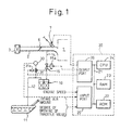
- Fig. 1 shows an internal combustion engine of an automobile to which the present invention is applied.
- reference numeral 1 designates an internal combustion engine for an automobile
- numeral 2 designates an intake air passage of the engine
- numeral 3 designates an air-cleaner disposed in the intake air passage 2.
- a throttle valve 6 which takes a degree of opening determined by the amount of depression of an accelerator pedal (not shown in the drawing) by the driver of the automobile, is disposed.
- Fuel in a fuel tank 11 is pressurized by a fuel pump (not shown) and is sent to a fuel injector 7 arranged in the intake air passage 2.
- the fuel injector 7 injects fuel into an intake port of each cylinder of the engine 1 in response to a signal from a control circuit 20.
- Numeral 20 in Fig. 1 denotes a control circuit of the engine 1.
- the control circuit 20 may, for example, consist of a microcomputer of a conventional type which comprises a ROM (read-only memory) 22, a RAM (random access memory) 23, a CPU (microprocessor) 24, an input port 25 and an output port 26 connected one another by a bi-directional bus 21.
- the control circuit 20 performs basic engine control such as fuel injection control and ignition timing control of the engine 1. Further, in this embodiment, the control circuit 20 performs failure diagnosis of the evaporative emission control system as explained later in detail.
- the output port 26 of the control circuit 20 is connected to the fuel injector 7 through a drive circuit (not shown), to control an opening period, i.e., the fuel injection amount of the fuel injector 7.
- the output port 26 is also connected to a purge control valve 15, to control the degree of opening thereof.
- the input port 25 receives an engine speed from an engine speed signal sensor disposed signal at a crankshaft of the engine 1.
- the input port 25 also receives, through A/D (analog-to-digital) converters (not shown), a signal indicating the amount of intake air from an air flow meter disposed in the intake air passage 2, a signal indicating the degree of opening of the throttle valve 6 from a throttle opening sensor disposed at the throttle valve 6, and a signal from a pressure sensor 30.
- A/D analog-to-digital
- Numeral 10 in Fig. 1 denotes a canister for adsorbing fuel vapor evaporated from the fuel in the fuel tank 11.
- the canister 10 is connected to a space above a fuel level in the fuel tank 11 through a fuel vapor passage 12, and to the intake air passage 2 downstream of the throttle valve 6 through a purge gas passage 14.
- Numeral 15 in Fig. 1 denotes a purge control valve 15 which controls the flow rate of the purge gas from the canister 10 into the intake air passage 2 through the purge gas passage 14.
- the purge control valve 15 has, for example, a solenoid actuator.
- the control circuit 20 changes the duty ratio (the ratio of the length of an ON period to the length of one ON-OFF cycle period) of a pulse voltage signal for driving the solenoid actuator, to thereby control the degree of opening of the valve 15.
- the valve 15 is not limited to the solenoid type.
- the valve 15 may be driven by a diaphragm type negative pressure actuator.
- the negative pressure applied to the negative pressure actuator is controlled by a negative pressure control valve which is driven by a pulse voltage signal from the control circuit 20.
- the duty ratio of the drive pulse of the negative pressure control valve may be changed to control the degree of opening of the valve 15.
- Fig. 2 illustrates the construction of the canister 10 in Fig. 1.
- the canister 10 comprises a housing 10a and a fuel vapor adsorbent 13, such as active carbon, filled in the housing 10a.
- a fuel vapor adsorbent 13 such as active carbon
- an internal pressure control valve 16 and an atmospheric valve 18 are provided to control the operation for adsorption of fuel vapor to the adsorbent 13 and releasing of the adsorbed fuel vapor from the adsorbent (i.e., purging of fuel vapor from the adsorbent 13).
- the operation for adsorption and purging of fuel vapor will be explained later.
- the internal pressure control valve 16 comprises a port 16a communicating with the inside of the housing 10a and a diaphragm 16b.
- the diaphragm 16b is urged by the spring 16c to the port 16a so that the port 16a is closed by the diaphragm 16b.
- a pressure chamber 16d is formed on the spring 16c side of the diaphragm and communicates with the atmosphere.
- another pressure chamber 16f which communicates with the fuel tank 11a via the fuel vapor passage 12 is formed on the side of the diaphragm 16b opposite to the pressure chamber 16d.
- the pressure chamber 16f communicates with the inside of the housing 10a via a pressure equalizing valve 17 having a check ball 17a and spring 17b.
- the atmospheric valve 18 has a construction similar to that of the internal pressure control valve 16 and comprises a port 18a communicating with the inside of the housing 10a, a diaphragm 18b and a spring 18c.
- a pressure chamber 18d formed on the spring 18c side of the diaphragm 18b is connected to the section 13a, which is formed on the internal pressure control valve 16 side in the housing 10a, through a pipe 18g.
- a pressure chamber 18f formed on the side of the diaphragm 18b opposite to the pressure chamber 18d is connected to the air-cleaner 3 via a pipe 18e.
- Fig. 2 when the fuel temperature rises with the internal purge control valve 15 being closed, the pressure in the fuel tank 11 increases due to evaporation of fuel inside the fuel tank 11. Since the fuel vapor space above the fuel level in the fuel tank 11 communicates with the pressure chamber 16f in the internal pressure control valve 16, the pressure in the pressure chamber 16f also increases due to pressure rise in the fuel tank 11. Further, an atmospheric pressure is introduced to the pressure chamber 16d which is on the side of the diaphragm 16b opposite to the pressure chamber 16f, through the port 16e.
- the purge control valve 15 is opened. This causes the section 13a in the housing 10a to communicate with the intake air passage 2 at the portion downstream of the throttle valve 6 through the purge gas passage 14. When this occurs, a negative pressure in the intake air passage 2 downstream of the throttle valve 6 is introduced to the housing 10a and lowers the pressure inside the housing 10a. Since the pressure chamber 18d in the atmospheric valve 18 is connected to the section 13a inside the housing 10a through the pipe 18g, the pressure in the pressure chamber 18d also becomes lower than the atmospheric pressure.
- the diaphragm 18b is pushed by the pressure in the pressure chamber 18f which is connected to the air-cleaner 3 by the pipe 18e to open the port 18a against the urging force of the spring 18c.
- clean air from the air-cleaner 3 flows into the section 13b in the housing 10a through the pipe 19e and the port 18a.
- This clean air flows through the sections 13b and 13a of the adsorbent 13, then, flows into the intake air passage 2 via the purge gas passage 14.
- the fuel vapor adsorbed by the adsorbent 13 is released (purged) from the adsorbent and, thereby, the adsorbent 13 is prevented from being saturated with fuel vapor.
- Fuel vapor released from the adsorbent 13 mixes with clean air from the air-cleaner 3, and forms a mixture of air and fuel vapor (i.e., purge gas). Since this purge gas is fed to the engine 1 and burned in the combustion chamber thereof, emission of the evaporated fuel from the fuel tank 11 is prevented.
- the spring 18c of the atmospheric valve 18 is set in such a manner that the atmospheric valve 18 opens when the pressure inside the canister 10 becomes lower than the atmospheric pressure by, for example, about 1.5 Kpa (150 mmaq) to introduce clean air from the air-cleaner 3 into the canister 10.
- the adsorbent 13 in the canister 10 adsorbs and releases fuel vapor in accordance with opening and closing of the purge control valve 15 to prevent emission of fuel vapor to atmosphere.
- emission of fuel vapor may occur.
- the housing 10a of the canister 10 has a leak, fuel in the fuel tank 11 and canister 10 may leak into the atmosphere.
- a pressure sensor 30 (Fig. 1) is provided in order to detect such a failure.
- the pressure sensor 30 generates a voltage signal corresponding to the difference between the pressure to be detected and the atmospheric pressure, and this analogue voltage signal is fed to the input port 25 of the control circuit 20 after it is converted to digital signal by an A/D converter (not shown).
- the pressure sensor 30 is connected to the fuel vapor passage 12 and the portion of the purge gas passage 14 between the canister 10 and the purge control valve 15 via a three-way switching valve 31 so that it can detect the pressure in the fuel vapor passage 12 (i.e., the pressure in the fuel tank 11) and the pressure in the purge gas passage 14 (i.e., the pressure in the canister housing 10a) selectively by switching the three-way switching valve 31.
- Numeral 31a in Fig. 1 shows an actuator of appropriate type, such as a solenoid actuator or a diaphragm type negative pressure actuator.
- the actuator 31a is connected to the output port 26 of the control circuit 20 via a drive circuit (not shown) and switches the three-way switching valve 31 in response to a driving signal from the control circuit 20.
- the diagnostic device diagnoses the canister 10 when the purge control valve 15 is closed and when the internal pressure of the canister 10 is stable.
- the fuel vapor flows from the fuel tank 11 into the canister 10 through the internal pressure control valve 16. If the canister 10 has a leak, the fuel vapor (or a remnant of air after the fuel vapor is adsorbed by the adsorbent 13) flows out from the canister 10 through the leak. As a result, the pressure of the canister 10 becomes equal to the atmospheric pressure.
- the pressure of the canister 10 stays always negative. If the temperature of the fuel is high and the pressure of the fuel tank 11 is higher than the opening pressure of the valve 16, fuel vapor flows from the fuel tank 11 into the canister 10 and, thereby the pressure of the canister 10 increases. Since the valve 16 is designed to open when the pressure of the fuel tank 11 is greater than the atmospheric pressure by, for example, 1 Kpa, the pressure of the canister 10 becomes higher than the atmospheric pressure in this case.
- Fig. 3 is a flowchart showing the failure diagnosis operation in this embodiment. This routine is executed by the control circuit 20 at predetermined intervals.
- step 301 it is determined whether the conditions to carry out a failure diagnosis are satisfied.
- the failue diagnosis is carried out when a certain time has lapsed after the purge control valve 15 is closed and the pressure of the canister 10 is stabilized.
- the conditions checked by step 301 are (1) the engine is not started, or (2) the valve 15 has never been opened after the start of the engine. When the engine is stopped, the valve 15 is closed. Before the start of the engine, therefore, it is considered that the valve 15 has been closed for relatively a long time. Accordingly, if the condition (1) is satisfied, it is considered that the pressure of the canister 10 is stable.
- the failure diagnosis may be carried out after the start of the engine only when the negative pressure of the intake air passage 2 after the start of the engine is smaller than a predetermined value, i.e., only when the absolute pressure of the intake air passage is higher than a predetermined value.
- step 303 reads the output of the pressure sensor 30.
- the pressure sensor 30 detects a gauge pressure, i.e., the difference between the atmospheric pressure and a pressure to be detected, and therefore, the detected pressure P of the pressure sensor 30 indicates the difference between the atmospheric pressure and the pressure of the canister 10.
- Step 305 determines whether
- step 307 sets a flag FX to 0, and the routine terminates this time. If
- an alarm (not shown) may be activated to inform the driver of the automobile that a failure has occurfed in the evaporative emission control system.
- another failure diagnosis which will be explained later, may be carried out to determine whether the canister 10 has really failed, to thereby improve the accuracy of the failure diagnosis.
- the reference value P 0 used in step 305 is determined according to the size of a leak of the canister 10 to be detected. If the size of the leak to be detected is large, P 0 may be set at a small value, and if a leak of a small size must be detected, P 0 must be set at a large value. In this embodiment, the diagnostic device is directed to detect a relatively large leak. Therefore, P 0 is set at a relatively small value. However, in this case, if P 0 is set at very small value, an error in the failure diagnosis may occur due to a tolerance of the accuracy of the pressure sensor 30. Taking this into consideration, P 0 is set at a larger value than the tolerance of the pressure sensor 30 (for example, 0.2 to 0.3 Kpa) in this embodiment.
- the failure diagnosis can be performed even when the temperature of fuel in the fuel tank 11 is high if the internal pressure of the canister 10 is stable. Therefore, since the diagnosis can be performed before every engine start, thereby the frequency of performing the diagnosis is largely increased.
- the conditions used at step 401 to determine whether the failure diagnosis can be carried out are, for example, (1) whether the temperature of cooling water of the engine is sufficiently high (for example, above 80°C), and (2) whether the concentration of fuel in the purge gas is not excessively high. Only when these conditions are both satisfied, is the failure diagnosis carried out.
- the condition (1) is used to carry out the failure diagnosis only when the operating conditions of the engine are stable. This is required because the amount of fuel supplied to the engine temporarily fluctuates when a purging operation is stopped to carry out the failure diagnosis.
- the condition (2) is required to prevent a large fluctuation in the amount of fuel supplied to the engine due to the termination of the purging operation, i.e., to prevent a large fluctuation in the operating air-fuel ratio of the engine.
- the flow rate of the purge gas may be directly detected by a flow meter disposed in the purge gas passage 14.
- the flow rate of the purge gas is indirectly detected based on the degree of opening of the purge control valve 15, i.e., the duty ratio of the pulse signal for driving the valve 15.
- the degree of opening of the valve 15 is large, the flow rate of the purge gas is large, and when it is small the flow rate is small. Accordingly, in this comparative example, the failure diagnosis is permitted only when the degree of opening of the valve 15, i.e., the duty ratio of the driving pulse is smaller than a reference value.
- the reference value used in step 403 to check the duty ratio of the driving pulse of the valve 15, i.e., the flow rate of the purge gas is determined based on conditions in which the pressure in the intake air passage 2 becomes the lowest (in other words, the maximum negative pressure), i.e., based on conditions in which the flow rate of the purge gas becomes maximum at a given degree of opening of the purge control valve 15. Accordingly, the reference value used in this comparative example is relatively small and corresponds to, for example, a duty ratio of about 50%. If the degree of opening of the valve 15 is less than the reference value (50%), the flow rate of air flowing through the atmospheric valve 18 into the canister 10 is less than a predetermined value irrespective of the negative pressure of the intake air passage 2.
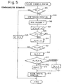
- Step 501 the failure diagnosis operation from steps 503 to 523 are performed only when the value of the flag KF is set to 1 in the routine of Fig. 4.
- Step 505 reads the output of the pressure sensor 30 through the AD converter.
- Step 507 increments a counter KT by one. If the flag KF is not 1 in step 501, the counter KT is cleared in step 525. Only after the flag KF is set to 1, is the counter KT incremented by one in step 507 whenever the routine is executed.
- the counter KT indicates a time after the flag KF is set to 1, i.e., a time after the failure diagnosis is started.
- step 511 stores the pressure of the canister 10 as P 1 .
- step 515 stores the pressure of the canister 10 as P 2 .
- Step 517 determines whether an increase (P 2 - P 1 ) in the pressure of the canister 10 between the time KT 1 and the time KT 2 is greater than a reference value P 10 . If (P 2 - P 1 ) ⁇ P 10 , the canister 10 is determined as being failed, and step 519 sets a failure flag FX to 1. If (P 2 - P 1 ) ⁇ P 10 , the canister 10 is determined as being normal, and step 521 sets the flag FX to 0.
- the reference value KT 1 is set to a value corresponding to a time period sufficient to stabilize an instantaneous fluctuation in the pressure of the canister 10 due to the closure of the valve 15 (for example, 0.5 seconds).
- the reference value KT 2 is set to a value corresponding a time period sufficient to detect a pressure increase if the canister 10 has a leak (for example, 1.5 seconds).
- a relatively large value is used as the reference value P 10 in this comparative example when the flow rate of the purge gas is large, i.e., when the increase in the pressure of the canister 10 due to a leak is large.
- a relatively small value is used as the reference value P 10 .
- the pressure of the canister 10 stays around the atmospheric pressure as indicated by the curve B. Therefore, it might be possible to determine the failure of the canister 10 by measuring the pressure of the canister 10 at a time point of, for example, Q in Fig. 7, i.e., a certain time after the closure of the purge control valve 15, and by determining that the canister is normal if the measured pressure is higher than the atmospheric pressure.
- the pressure of the canister 10 however, sometimes changes as indicated by a curve D in Fig. 7, depending on the flow rate of the purge gas. In this case, if the failure diagnosis is carried out only according to the pressure measured at the point Q, the canister 10 will be determined as being failed even if it is normal. Since pressure of the canister 10 that follows the curve D does not stay around the atmospheric pressure but continuously increases, this comparative example determines whether the canister 10 is normal according to not only the pressure measured at the point Q but also an increase in the pressure of the canister 10 within a predetermined period, to thereby avoid the error in the diagnosis mentioned above.
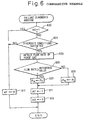
- step 801 carries out the same failure diagnosis as explained in Fig. 5. Then, step 803 determines whether the failure flag FX set in step 801 is 1, to see if the canister 10 has been determined as being failed.
- step 821 clears the counter TC, and the routine terminates with the purge control valve 15 being opened at step 523 of Fig. 5.
- a canister adsorbs fuel vapor sent from a fuel tank of an engine.
- the canister is connected to an intake air passage through a purge gas passage and a purge control valve.
- a control circuit employs a pressure sensor to detect the pressure of the canister when the purge control valve is closed and when the pressure of the canister is stabilized.
- the control circuit carries out a failure diagnosis based on this pressure. Namely, when the pressure of the canister after it is stabilized deviates from the atmospheric pressure by more than a predetermined reference value, the control circuit determines that the canister has failed, i.e., the canister has a leak. Since the diagnosis can be carried out before starting the engine, the diagnosis can be correctly carried out without affecting the operation of the engine.
Landscapes
- Engineering & Computer Science (AREA)
- Chemical & Material Sciences (AREA)
- Combustion & Propulsion (AREA)
- Mechanical Engineering (AREA)
- General Engineering & Computer Science (AREA)
- Supplying Secondary Fuel Or The Like To Fuel, Air Or Fuel-Air Mixtures (AREA)
Claims (1)
- Dispositif de diagnostic d'un système de commande d'émission des vapeurs, comprenant :caractérisé parun récipient (10) adsorbant les vapeurs de carburant envoyées depuis un réservoir de carburant (11) d'un moteur à combustion interne (1), un passage de vapeur de carburant (12) raccordant un espace au-dessus d'un niveau de carburant dans le réservoir de carburant (11) au récipient (10), un passage de gaz de purge (14) raccordant le récipient (10) à un passage d'air d'admission (2) du moteur ( 1), et une soupape de commande de purge (15) ouvrant et fermant le passage gaz de purge (14) ;un dispositif de détection de pression (30) détectant la pression interne du récipient (10),un moyen de détermination (20) déterminant que le récipient (10) est normal si la différence entre la pression interne du récipient (10) détecté par le dispositif de détection de pression (30) et la pression atmosphérique est supérieure à une valeur de référence (P 0), lorsque la soupape de commande de purge (15) est fermé et que la pression interne est stable,dans lequel le moyen de détermination (1) opère pour déterminer si le récipient (10) est normal que lorsqu'une des conditions suivantes est satisfaite :le moteur (1) n'est pas démarré ; etla soupape de commande de purge (15) n'a jamais été ouverte après le démarrage du moteur (1).
Priority Applications (1)
| Application Number | Priority Date | Filing Date | Title |
|---|---|---|---|
| EP00119659A EP1054151B1 (fr) | 1995-03-20 | 1996-03-19 | Un dispositif de diagnostic pour un système de commande des émissions de vapeur |
Applications Claiming Priority (3)
| Application Number | Priority Date | Filing Date | Title |
|---|---|---|---|
| JP06085895A JP3198865B2 (ja) | 1995-03-20 | 1995-03-20 | エバポパージシステムの故障診断装置 |
| JP60858/95 | 1995-03-20 | ||
| JP6085895 | 1995-03-20 |
Related Child Applications (2)
| Application Number | Title | Priority Date | Filing Date |
|---|---|---|---|
| EP00119659A Division EP1054151B1 (fr) | 1995-03-20 | 1996-03-19 | Un dispositif de diagnostic pour un système de commande des émissions de vapeur |
| EP00119659.1 Division-Into | 2000-09-08 |
Publications (3)
| Publication Number | Publication Date |
|---|---|
| EP0733794A2 EP0733794A2 (fr) | 1996-09-25 |
| EP0733794A3 EP0733794A3 (fr) | 1997-10-01 |
| EP0733794B1 true EP0733794B1 (fr) | 2002-02-27 |
Family
ID=13154508
Family Applications (2)
| Application Number | Title | Priority Date | Filing Date |
|---|---|---|---|
| EP96104346A Expired - Lifetime EP0733794B1 (fr) | 1995-03-20 | 1996-03-19 | Dispositif de diagnostic pour un système de commande des émissions de vapeur |
| EP00119659A Expired - Lifetime EP1054151B1 (fr) | 1995-03-20 | 1996-03-19 | Un dispositif de diagnostic pour un système de commande des émissions de vapeur |
Family Applications After (1)
| Application Number | Title | Priority Date | Filing Date |
|---|---|---|---|
| EP00119659A Expired - Lifetime EP1054151B1 (fr) | 1995-03-20 | 1996-03-19 | Un dispositif de diagnostic pour un système de commande des émissions de vapeur |
Country Status (4)
| Country | Link |
|---|---|
| US (1) | US5669362A (fr) |
| EP (2) | EP0733794B1 (fr) |
| JP (1) | JP3198865B2 (fr) |
| DE (2) | DE69619414T2 (fr) |
Families Citing this family (21)
| Publication number | Priority date | Publication date | Assignee | Title |
|---|---|---|---|---|
| US5996400A (en) * | 1996-03-29 | 1999-12-07 | Mazda Motor Corporation | Diagnostic system for detecting leakage of fuel vapor from purge system |
| US5816223A (en) * | 1997-12-29 | 1998-10-06 | Ford Global Technologies, Inc. | Evaporative emission control system for providing fuel to vapor to automotive engine |
| DE19818697A1 (de) * | 1998-04-25 | 1999-10-28 | Opel Adam Ag | Verfahren zur Bestimmung von Leckagen im Kraftstoffversorgungssystem eines Kraftfahrzeuges |
| US5878729A (en) * | 1998-05-06 | 1999-03-09 | General Motors Corporation | Air control valve assembly for fuel evaporative emission storage canister |
| JP3729683B2 (ja) * | 1998-12-04 | 2005-12-21 | トヨタ自動車株式会社 | エバポパージシステムの故障診断装置 |
| JP3561649B2 (ja) * | 1999-02-05 | 2004-09-02 | 本田技研工業株式会社 | 内燃機関の蒸発燃料処理装置 |
| JP3501020B2 (ja) * | 1999-04-01 | 2004-02-23 | トヨタ自動車株式会社 | 蒸発燃料パージシステムの故障診断装置 |
| JP3621297B2 (ja) * | 1999-06-30 | 2005-02-16 | 株式会社日立ユニシアオートモティブ | 蒸発燃料処理装置の故障診断装置 |
| JP3681595B2 (ja) * | 1999-12-20 | 2005-08-10 | 本田技研工業株式会社 | 蒸発燃料処理装置 |
| US6557401B2 (en) | 2000-04-11 | 2003-05-06 | Toyota Jidosha Kabushiki Kaisha | Method and apparatus for detecting abnormalities in fuel systems |
| JP3844706B2 (ja) * | 2001-07-30 | 2006-11-15 | 日産自動車株式会社 | 燃料蒸気ガス処理装置 |
| US8631783B2 (en) * | 2009-11-18 | 2014-01-21 | GM Global Technology Operations LLC | Method and apparatus for controlling engine torque during intrusive testing |
| KR101261945B1 (ko) * | 2010-11-12 | 2013-05-09 | 기아자동차주식회사 | 차량용 캐니스터 및 이를 구비한 연료 증발계 장치 |
| JP5725376B2 (ja) * | 2012-09-06 | 2015-05-27 | 株式会社デンソー | 電磁弁制御装置、および、電磁弁制御方法 |
| US9316558B2 (en) * | 2013-06-04 | 2016-04-19 | GM Global Technology Operations LLC | System and method to diagnose fuel system pressure sensor |
| US20150085894A1 (en) * | 2013-09-24 | 2015-03-26 | Ford Global Technologies, Llc. | Method for diagnosing fault within a fuel vapor system |
| US9797344B2 (en) | 2014-08-29 | 2017-10-24 | GM Global Technology Operations LLC | System and method for diagnosing a dual path purge system using a hydrocarbon sensor and for diagnosing a hydrocarbon sensor in a single path purge system or a dual path purge system |
| US9562499B2 (en) * | 2014-08-29 | 2017-02-07 | GM Global Technology Operations LLC | Purge valve detachment diagnostic systems and methods |
| JP7027942B2 (ja) * | 2018-02-22 | 2022-03-02 | トヨタ自動車株式会社 | 蒸発燃料処理装置 |
| CN113915031B (zh) * | 2021-10-18 | 2022-06-17 | 苏州恩都法汽车系统有限公司 | 油箱隔离阀控制系统 |
| WO2025006449A1 (fr) * | 2023-06-29 | 2025-01-02 | Phinia Jersey Holdings Llc | Ensemble filtre à air autonettoyant |
Family Cites Families (14)
| Publication number | Priority date | Publication date | Assignee | Title |
|---|---|---|---|---|
| JPH0623736Y2 (ja) * | 1988-08-10 | 1994-06-22 | トヨタ自動車株式会社 | 内燃機関のエバポパージ異常検出装置 |
| JP2748723B2 (ja) * | 1991-06-10 | 1998-05-13 | トヨタ自動車株式会社 | エバポパージシステムの故障診断装置 |
| US5299544A (en) * | 1991-06-17 | 1994-04-05 | Honda Giken Kogyo Kabushiki Kaisha | Evaporative fuel-purging control system for internal combustion engines |
| JPH0539754A (ja) * | 1991-07-31 | 1993-02-19 | Suzuki Motor Corp | エバポシステム |
| DE4132055A1 (de) * | 1991-09-26 | 1993-04-01 | Bosch Gmbh Robert | Verfahren und vorrichtung zum pruefen der funktionsfaehigkeit einer tankentlueftungsanlage |
| JPH0642414A (ja) * | 1992-07-23 | 1994-02-15 | Toyota Motor Corp | エバポパージシステムの故障診断装置 |
| US5295472A (en) * | 1992-01-06 | 1994-03-22 | Toyota Jidosha Kabushiki Kaisha | Apparatus for detecting malfunction in evaporated fuel purge system used in internal combustion engine |
| JP2688674B2 (ja) * | 1992-01-20 | 1997-12-10 | 本田技研工業株式会社 | 燃料タンク内圧センサの故障検出装置及び故障補償装置 |
| JP2746016B2 (ja) * | 1992-11-05 | 1998-04-28 | トヨタ自動車株式会社 | エバポパージシステムの故障診断装置 |
| JP2825399B2 (ja) * | 1992-08-21 | 1998-11-18 | 三菱電機株式会社 | 蒸発燃料制御装置 |
| DE4227698C2 (de) * | 1992-08-21 | 1996-08-01 | Daimler Benz Ag | Verfahren zur Ermittlung von Undichtheiten in einer Kraftfahrzeug-Tankentlüftungsanlage |
| JP2741702B2 (ja) * | 1992-12-02 | 1998-04-22 | 本田技研工業株式会社 | 内燃エンジンの蒸発燃料処理装置 |
| JP3630711B2 (ja) * | 1994-01-31 | 2005-03-23 | 富士重工業株式会社 | 車両用燃料タンクの内圧調整装置 |
| US5494021A (en) * | 1994-09-15 | 1996-02-27 | Nissan Motor Co., Ltd. | Evaporative purge monitoring method and system |
-
1995
- 1995-03-20 JP JP06085895A patent/JP3198865B2/ja not_active Expired - Lifetime
-
1996
- 1996-03-18 US US08/617,252 patent/US5669362A/en not_active Expired - Lifetime
- 1996-03-19 EP EP96104346A patent/EP0733794B1/fr not_active Expired - Lifetime
- 1996-03-19 DE DE69619414T patent/DE69619414T2/de not_active Expired - Lifetime
- 1996-03-19 EP EP00119659A patent/EP1054151B1/fr not_active Expired - Lifetime
- 1996-03-19 DE DE69624597T patent/DE69624597T2/de not_active Expired - Lifetime
Also Published As
| Publication number | Publication date |
|---|---|
| JP3198865B2 (ja) | 2001-08-13 |
| JPH08261073A (ja) | 1996-10-08 |
| EP1054151A3 (fr) | 2000-11-29 |
| DE69624597D1 (de) | 2002-12-05 |
| US5669362A (en) | 1997-09-23 |
| EP0733794A2 (fr) | 1996-09-25 |
| DE69619414D1 (de) | 2002-04-04 |
| EP1054151B1 (fr) | 2002-10-30 |
| DE69624597T2 (de) | 2003-03-27 |
| DE69619414T2 (de) | 2002-07-18 |
| EP1054151A2 (fr) | 2000-11-22 |
| EP0733794A3 (fr) | 1997-10-01 |
Similar Documents
| Publication | Publication Date | Title |
|---|---|---|
| EP0733794B1 (fr) | Dispositif de diagnostic pour un système de commande des émissions de vapeur | |
| EP0735264B1 (fr) | Appareil de diagnostic d'erreur pour système depurge de carburant évaporé | |
| US5245973A (en) | Failure detection device for evaporative fuel purge system | |
| JP3269751B2 (ja) | 内燃機関制御装置 | |
| US5767395A (en) | Function diagnosis apparatus for evaporative emission control system | |
| JP2007187011A (ja) | 蒸発燃料処理装置 | |
| JPH0642415A (ja) | 内燃エンジンの蒸発燃料処理装置 | |
| JP4598193B2 (ja) | 蒸発燃料処理装置 | |
| EP0733793B1 (fr) | Système de commande des émissions de vapeur pour un moteur à combustion interne | |
| JP3147001B2 (ja) | エバポパージシステムの故障診断装置 | |
| US5203870A (en) | Method and apparatus for detecting abnormal state of evaporative emission-control system | |
| JP3481681B2 (ja) | 燃料蒸発ガス処理装置の故障診断装置 | |
| JPH06235355A (ja) | 内燃機関の蒸発燃料蒸散防止装置の故障診断装置 | |
| JP3264176B2 (ja) | エバポシステムの診断方法 | |
| JPH0723706B2 (ja) | エンジンの蒸発燃料処理装置 | |
| JPH0681728A (ja) | エバポパージシステムの故障診断装置 | |
| JPH08326611A (ja) | 内燃機関の制御装置 | |
| JP2745984B2 (ja) | エバポパージシステムの故障診断装置 | |
| JPH06147031A (ja) | エバポパージシステムの故障診断装置 | |
| JPH07189831A (ja) | 燃料蒸発ガス抑止装置の診断装置 | |
| JPH0737778B2 (ja) | 空燃比制御系の故障診断装置 | |
| JPH06117332A (ja) | エバポパージシステムの故障診断装置 | |
| JPS63100253A (ja) | 空燃比制御システムの故障診断装置 | |
| JPH0642413A (ja) | エバポパージシステムの故障診断装置 | |
| JPH0658212A (ja) | エバポパージシステムの故障診断装置 |
Legal Events
| Date | Code | Title | Description |
|---|---|---|---|
| PUAI | Public reference made under article 153(3) epc to a published international application that has entered the european phase |
Free format text: ORIGINAL CODE: 0009012 |
|
| 17P | Request for examination filed |
Effective date: 19960319 |
|
| AK | Designated contracting states |
Kind code of ref document: A2 Designated state(s): DE FR GB |
|
| PUAL | Search report despatched |
Free format text: ORIGINAL CODE: 0009013 |
|
| AK | Designated contracting states |
Kind code of ref document: A3 Designated state(s): DE FR GB |
|
| 17Q | First examination report despatched |
Effective date: 20000508 |
|
| GRAG | Despatch of communication of intention to grant |
Free format text: ORIGINAL CODE: EPIDOS AGRA |
|
| GRAG | Despatch of communication of intention to grant |
Free format text: ORIGINAL CODE: EPIDOS AGRA |
|
| GRAH | Despatch of communication of intention to grant a patent |
Free format text: ORIGINAL CODE: EPIDOS IGRA |
|
| GRAH | Despatch of communication of intention to grant a patent |
Free format text: ORIGINAL CODE: EPIDOS IGRA |
|
| REG | Reference to a national code |
Ref country code: GB Ref legal event code: IF02 |
|
| GRAA | (expected) grant |
Free format text: ORIGINAL CODE: 0009210 |
|
| AK | Designated contracting states |
Kind code of ref document: B1 Designated state(s): DE FR GB |
|
| REF | Corresponds to: |
Ref document number: 69619414 Country of ref document: DE Date of ref document: 20020404 |
|
| PLBE | No opposition filed within time limit |
Free format text: ORIGINAL CODE: 0009261 |
|
| STAA | Information on the status of an ep patent application or granted ep patent |
Free format text: STATUS: NO OPPOSITION FILED WITHIN TIME LIMIT |
|
| 26N | No opposition filed |
Effective date: 20021128 |
|
| REG | Reference to a national code |
Ref country code: GB Ref legal event code: 746 Effective date: 20121221 |
|
| REG | Reference to a national code |
Ref country code: DE Ref legal event code: R084 Ref document number: 69619414 Country of ref document: DE Effective date: 20121219 |
|
| REG | Reference to a national code |
Ref country code: FR Ref legal event code: PLFP Year of fee payment: 20 |
|
| PGFP | Annual fee paid to national office [announced via postgrant information from national office to epo] |
Ref country code: DE Payment date: 20150310 Year of fee payment: 20 |
|
| PGFP | Annual fee paid to national office [announced via postgrant information from national office to epo] |
Ref country code: GB Payment date: 20150318 Year of fee payment: 20 Ref country code: FR Payment date: 20150309 Year of fee payment: 20 |
|
| REG | Reference to a national code |
Ref country code: DE Ref legal event code: R071 Ref document number: 69619414 Country of ref document: DE |
|
| REG | Reference to a national code |
Ref country code: GB Ref legal event code: PE20 Expiry date: 20160318 |
|
| PG25 | Lapsed in a contracting state [announced via postgrant information from national office to epo] |
Ref country code: GB Free format text: LAPSE BECAUSE OF EXPIRATION OF PROTECTION Effective date: 20160318 |