EP0733831A2 - Stufenloses Getriebe - Google Patents
Stufenloses Getriebe Download PDFInfo
- Publication number
- EP0733831A2 EP0733831A2 EP96104524A EP96104524A EP0733831A2 EP 0733831 A2 EP0733831 A2 EP 0733831A2 EP 96104524 A EP96104524 A EP 96104524A EP 96104524 A EP96104524 A EP 96104524A EP 0733831 A2 EP0733831 A2 EP 0733831A2
- Authority
- EP
- European Patent Office
- Prior art keywords
- hydraulic
- valve
- pulley
- port
- continuously variable
- Prior art date
- Legal status (The legal status is an assumption and is not a legal conclusion. Google has not performed a legal analysis and makes no representation as to the accuracy of the status listed.)
- Granted
Links
Images












Classifications
-
- F—MECHANICAL ENGINEERING; LIGHTING; HEATING; WEAPONS; BLASTING
- F16—ENGINEERING ELEMENTS AND UNITS; GENERAL MEASURES FOR PRODUCING AND MAINTAINING EFFECTIVE FUNCTIONING OF MACHINES OR INSTALLATIONS; THERMAL INSULATION IN GENERAL
- F16H—GEARING
- F16H37/00—Combinations of mechanical gearings, not provided for in groups F16H1/00 - F16H35/00
- F16H37/02—Combinations of mechanical gearings, not provided for in groups F16H1/00 - F16H35/00 comprising essentially only toothed or friction gearings
- F16H37/06—Combinations of mechanical gearings, not provided for in groups F16H1/00 - F16H35/00 comprising essentially only toothed or friction gearings with a plurality of driving or driven shafts; with arrangements for dividing torque between two or more intermediate shafts
- F16H37/08—Combinations of mechanical gearings, not provided for in groups F16H1/00 - F16H35/00 comprising essentially only toothed or friction gearings with a plurality of driving or driven shafts; with arrangements for dividing torque between two or more intermediate shafts with differential gearing
- F16H37/0833—Combinations of mechanical gearings, not provided for in groups F16H1/00 - F16H35/00 comprising essentially only toothed or friction gearings with a plurality of driving or driven shafts; with arrangements for dividing torque between two or more intermediate shafts with differential gearing with arrangements for dividing torque between two or more intermediate shafts, i.e. with two or more internal power paths
- F16H37/084—Combinations of mechanical gearings, not provided for in groups F16H1/00 - F16H35/00 comprising essentially only toothed or friction gearings with a plurality of driving or driven shafts; with arrangements for dividing torque between two or more intermediate shafts with differential gearing with arrangements for dividing torque between two or more intermediate shafts, i.e. with two or more internal power paths at least one power path being a continuously variable transmission, i.e. CVT
- F16H37/0846—CVT using endless flexible members
-
- F—MECHANICAL ENGINEERING; LIGHTING; HEATING; WEAPONS; BLASTING
- F16—ENGINEERING ELEMENTS AND UNITS; GENERAL MEASURES FOR PRODUCING AND MAINTAINING EFFECTIVE FUNCTIONING OF MACHINES OR INSTALLATIONS; THERMAL INSULATION IN GENERAL
- F16H—GEARING
- F16H61/00—Control functions within control units of change-speed- or reversing-gearings for conveying rotary motion ; Control of exclusively fluid gearing, friction gearing, gearings with endless flexible members or other particular types of gearing
- F16H61/66—Control functions within control units of change-speed- or reversing-gearings for conveying rotary motion ; Control of exclusively fluid gearing, friction gearing, gearings with endless flexible members or other particular types of gearing specially adapted for continuously variable gearings
- F16H61/662—Control functions within control units of change-speed- or reversing-gearings for conveying rotary motion ; Control of exclusively fluid gearing, friction gearing, gearings with endless flexible members or other particular types of gearing specially adapted for continuously variable gearings with endless flexible members
- F16H61/6625—Control functions within control units of change-speed- or reversing-gearings for conveying rotary motion ; Control of exclusively fluid gearing, friction gearing, gearings with endless flexible members or other particular types of gearing specially adapted for continuously variable gearings with endless flexible members controlling shifting exclusively as a function of torque
-
- F—MECHANICAL ENGINEERING; LIGHTING; HEATING; WEAPONS; BLASTING
- F16—ENGINEERING ELEMENTS AND UNITS; GENERAL MEASURES FOR PRODUCING AND MAINTAINING EFFECTIVE FUNCTIONING OF MACHINES OR INSTALLATIONS; THERMAL INSULATION IN GENERAL
- F16H—GEARING
- F16H61/00—Control functions within control units of change-speed- or reversing-gearings for conveying rotary motion ; Control of exclusively fluid gearing, friction gearing, gearings with endless flexible members or other particular types of gearing
- F16H61/66—Control functions within control units of change-speed- or reversing-gearings for conveying rotary motion ; Control of exclusively fluid gearing, friction gearing, gearings with endless flexible members or other particular types of gearing specially adapted for continuously variable gearings
- F16H61/662—Control functions within control units of change-speed- or reversing-gearings for conveying rotary motion ; Control of exclusively fluid gearing, friction gearing, gearings with endless flexible members or other particular types of gearing specially adapted for continuously variable gearings with endless flexible members
- F16H61/66254—Control functions within control units of change-speed- or reversing-gearings for conveying rotary motion ; Control of exclusively fluid gearing, friction gearing, gearings with endless flexible members or other particular types of gearing specially adapted for continuously variable gearings with endless flexible members controlling of shifting being influenced by a signal derived from the engine and the main coupling
- F16H61/66259—Control functions within control units of change-speed- or reversing-gearings for conveying rotary motion ; Control of exclusively fluid gearing, friction gearing, gearings with endless flexible members or other particular types of gearing specially adapted for continuously variable gearings with endless flexible members controlling of shifting being influenced by a signal derived from the engine and the main coupling using electrical or electronical sensing or control means
-
- F—MECHANICAL ENGINEERING; LIGHTING; HEATING; WEAPONS; BLASTING
- F16—ENGINEERING ELEMENTS AND UNITS; GENERAL MEASURES FOR PRODUCING AND MAINTAINING EFFECTIVE FUNCTIONING OF MACHINES OR INSTALLATIONS; THERMAL INSULATION IN GENERAL
- F16H—GEARING
- F16H37/00—Combinations of mechanical gearings, not provided for in groups F16H1/00 - F16H35/00
- F16H37/02—Combinations of mechanical gearings, not provided for in groups F16H1/00 - F16H35/00 comprising essentially only toothed or friction gearings
- F16H37/06—Combinations of mechanical gearings, not provided for in groups F16H1/00 - F16H35/00 comprising essentially only toothed or friction gearings with a plurality of driving or driven shafts; with arrangements for dividing torque between two or more intermediate shafts
- F16H37/08—Combinations of mechanical gearings, not provided for in groups F16H1/00 - F16H35/00 comprising essentially only toothed or friction gearings with a plurality of driving or driven shafts; with arrangements for dividing torque between two or more intermediate shafts with differential gearing
- F16H37/0833—Combinations of mechanical gearings, not provided for in groups F16H1/00 - F16H35/00 comprising essentially only toothed or friction gearings with a plurality of driving or driven shafts; with arrangements for dividing torque between two or more intermediate shafts with differential gearing with arrangements for dividing torque between two or more intermediate shafts, i.e. with two or more internal power paths
- F16H37/084—Combinations of mechanical gearings, not provided for in groups F16H1/00 - F16H35/00 comprising essentially only toothed or friction gearings with a plurality of driving or driven shafts; with arrangements for dividing torque between two or more intermediate shafts with differential gearing with arrangements for dividing torque between two or more intermediate shafts, i.e. with two or more internal power paths at least one power path being a continuously variable transmission, i.e. CVT
- F16H2037/088—Power-split transmissions with summing differentials, with the input of the CVT connected or connectable to the input shaft
-
- F—MECHANICAL ENGINEERING; LIGHTING; HEATING; WEAPONS; BLASTING
- F16—ENGINEERING ELEMENTS AND UNITS; GENERAL MEASURES FOR PRODUCING AND MAINTAINING EFFECTIVE FUNCTIONING OF MACHINES OR INSTALLATIONS; THERMAL INSULATION IN GENERAL
- F16H—GEARING
- F16H61/00—Control functions within control units of change-speed- or reversing-gearings for conveying rotary motion ; Control of exclusively fluid gearing, friction gearing, gearings with endless flexible members or other particular types of gearing
- F16H61/66—Control functions within control units of change-speed- or reversing-gearings for conveying rotary motion ; Control of exclusively fluid gearing, friction gearing, gearings with endless flexible members or other particular types of gearing specially adapted for continuously variable gearings
- F16H2061/6604—Special control features generally applicable to continuously variable gearings
- F16H2061/6614—Control of ratio during dual or multiple pass shifting for enlarged ratio coverage
Definitions
- the present invention relates to a continuously variable transmission using a belt type continuously variable transmission unit composed of a primary pulley and a secondary pulley composed of two sheaves and a belt trained around the primary and secondary pulleys, and more specifically, to control of the axial forces of the belt type continuously variable transmission unit when forward traveling and backward traveling are switched in a continuously variable transmission composed of the combination of the belt type continuously variable transmission unit and a planetary gear which is particularly suitable as a transmission in automobiles.
- an automatic continuously variable transmission having a belt type continuously variable transmission unit assembled therein has attracted attention as a transmission for automobiles to cope with the requirement for improving a fuel consumption ratio, a driving capability, and the like.
- a continuously variable transmission having a planetary gear train capable of changing a speed in the two stages of directly-coupled rotation and forward speed reducing rotation, a belt type continuously variable transmission unit and a planetary gear unit for synthesizing the rotation output from the above planetary gear train and the rotation output from the belt type continuously variable transmission unit and outputting the synthesized rotation for continuously changing a speed over a forward direction and a reverse direction by the combination of the two-stage speed change effected by the above planetary gear train and the continuously variable speed change effected by the belt type continuously variable transmission unit.
- the speed reducing forward rotation of the planetary gear train is executed. Then, the speed reducing forward rotation is coupled with the speed changing rotation of the belt type continuously variable transmission unit and taken out from the planetary gear unit as a forward continuously variable rotation.
- the select lever is set to a R position
- the directly-coupled rotation of the planetary gear train is executed. Then, the directly-coupled rotation is coupled with the rotation of the belt type continuously variable transmission unit likewise and taken out from the planetary gear unit as a reverse continuously variable rotation.
- the direction in which power is transmitted by the belt type continuously variable transmission unit that is, the driving/driven relationship between a primary pulley and a secondary pulley is switched in a forward traveling state (D position) and a reverse traveling state (R position) due to torque circulation.
- the belt type continuously variable transmission unit changes a pulley ratio to thereby change a speed by changing axial forces (belt holding pressures) acting on both driving and driven side pulleys.
- the ratio of axial forces acting on both the pulleys must be set to a predetermined value to transmit power by setting both the pulleys to a predetermined pulley ratio, the axial force of the driving side pulley must be made larger than that of the driven side pulley at the time.
- An object of the present invention is to provide a continuously variable transmission capable of solving the above problem by changing the axial forces acting on both the pulleys of a belt type continuously variable transmission unit.
- the present invention according to claim 1 made by taking the above circumstances into consideration is characterized in a continuously variable transmission (1) comprising an input shaft (3) associated with an engine output shaft (2), an output shaft (5) associated with wheels, a belt type continuously variable transmission unit (11) having a first pulley (7) associated with the input shaft, a second pulley (9), a belt (10) trained around both the pulleys and an axial force actuating means (32, 33) for applying axial forces to both the pulleys for changing the pulley ratio of the first and second pulleys, a planetary gear (19) having at least first, second and third rotary elements (19s, 19c, 19r) with the first rotary element associated with the input shaft (3), the second rotary element associated with the second pulley (9) and the third rotary element associated with the output shaft (5), respectively, and a selection means for selecting at least a forward traveling state and backward traveling state of a vehicle, wherein a torque transmitting direction is changed between the first and second pulleys (7, 9)
- the axial force actuating means has a first hydraulic servo (32) acting on the first pulley (7) and a second hydraulic servo (33) acting on the second pulley (9) and applies axial forces to the first and second pulleys by supplying hydraulic pressures to the first and second hydraulic servos from an oil pump (17), and the switching means is composed of a switching valve (59, 59') for switching the hydraulic pressure acting on the first hydraulic servo and the hydraulic pressure acting on the second hydraulic servo.
- the switching valve is a manual valve (59, 59') integrally associating with the selection means.
- each of the above first and second hydraulic servos (32), (33) has a plurality of hydraulic chambers (45), (57), (46), (49), and the above switching valve (59) selectively switches the above hydraulic chambers to which hydraulic pressures are supplied to thereby reverse the effective pressure receiving areas of the first and second hydraulic servos, as shown in, for example, FIG. 4 to FIG. 8 and FIG. 14.
- each of the first and second hydraulic servos (32), (33) has at least a first hydraulic chamber (45), (46) and a second hydraulic chamber (47, (49), respectively as well as the first hydraulic chambers (45), (46) of both the hydraulic servos have the same effective pressure-receiving areas
- the control means (54, 541) has a regulator valve (56) and a ratio control valve (57)
- the hydraulic pressure from the regulator valve is supplied to the first hydraulic chambers (45), (46) of the both hydraulic servos at all times as well as the hydraulic pressure from the ratio control valve (57) is supplied to the second hydraulic chamber (57 or 49) of any one of both the hydraulic servos
- the switching valve (59) reverses the communication of the ratio control valve (57) with any one of the second hydraulic chambers (49 or 47) to the other of them.
- the regulator valve (56) and the ratio control valve (57) are interposed between the oil pump (17) and the switching valve (59).
- control means (54', 54 2 ) has first and second regulator valves (56), (57) for adjusting the hydraulic pressure from the oil pump (17) to respective hydraulic pressures, any one of the first and second regulator valves is caused to communicate with any one of the first and second hydraulic servos and the other of the regulator valves is caused to communicate with the other of the hydraulic servos, respectively, and the switching valve (59') reverses the communication of the first and second regulator valves with the first and second hydraulic servos as shown in, for example.
- the first and second regulator valves (56), (57) are interposed between the oil pump (17) and the switching valve (59).
- a relief valve (58) which makes the hydraulic pressure of the hydraulic servo on which a high hydraulic pressure acts lower than the hydraulic pressure of the hydraulic servo on which a low hydraulic pressure acts when it is determined that the vehicle is in a coast state.
- the input shaft (3) is coupled with the first pulley (7) and the first rotary element, respectively so that the direction in the input shaft of the torque transmitted from the first pulley and the direction in the input shaft of the torque transmitted from the first rotary element are reversed each other, respectively, as shown in, for example, FIG. 1 and FIG 24 to FIG. 26.
- the engine output from the input shaft (3) is subjected to a proper speed changing operation effected by the belt type continuously variable transmission unit (11) and transmitted to the second rotary element of the planetary gear (19) as well as a constant rotation is transmitted to the first rotary element, then both the rotations are synthesized by the planetary gear (19) and taken out from the third rotary element by the output shaft (5).
- the axial force actuating means (32), (33) is controlled by the control means (54, 54', 54 1 , 54 2 )
- the axial force of the first or second pulley (7), (9) is changed, so that the pulley ratio of the belt type continuously variable transmission unit (11) is changed to a predetermined pulley ratio so as to properly change the speed thereof.
- the forward traveling state or the backward traveling state is selected by the selection means, the direction of torque output from the output shaft (5) is changed to a forward rotation of the reverse rotation as well as the torque transmitting direction of the belt type continuously variable transmission unit (11) is changed.
- the switching means switches the relative relationship in magnitude of the axial forces acting on both the pulleys so as to coincide with the relationship of the axial forces of both the pulleys of the belt type continuously variable transmission unit whose torque transmitting direction is reversed by the torque circulation, so that the forward traveling and backward traveling can be securely and promptly switched.
- the switching valve is composed of the manual valve, a driver can securely switch the forward traveling and backward traveling based on his intention.
- each of the first and second hydraulic servos has a plurality of hydraulic chambers, the forward traveling and backward traveling can be easily and securely switched by reversing the effective pressure-receiving areas of both the hydraulic servos by reversing the hydraulic pressures supplied to the hydraulic chambers without the need of controlling the regulation of the hydraulic pressures acting on both the hydraulic servos.
- the regulator valve and the ratio control valve when the regulator valve and the ratio control valve are disposed downstream of the switching valve, the number of valves must be increased or the function of a single valve must be increased.
- the regulator valve and the ratio control valve are interposed between the oil pump and the switching valve, the above increase is not needed and the arrangement can be simplified.
- the forward traveling and backward traveling can be securely and easily switched by reversing the axial forces of both the pulleys.
- the arrangement can be simplified without the need of an increase of the number of valves and an increase of the function of a single valve likewise claim 6.
- torque circulation is securely executed by the planetary gear.
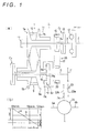
- a vehicle-mounted automatic continuously variable transmission 1 has a first shaft 3 aligned with an engine crank shaft 2, a second shaft 5 and a third shaft 6 (a, b) aligned with a front wheel shaft.
- a primary pulley 7 is supported by the input shaft 3
- a secondary pulley 9 is supported by the second shaft 5 and a belt 10 is trained around these two pulleys 7, 9 to thereby constitute a belt type continuously variable transmission unit 11.
- first shaft 3 is coupled with the engine crank shaft 2 through a damper 12 to thereby constitute an input shaft.
- the input side member 13 of a low clutch C L is fixed to the input shaft 3 as well as the output side member 15 of the low clutch C L is rotatably supported by the input shaft 3 and further a primary side sprocket 16 constituting the power transmission means is coupled with the output side member 15 integrally therewith.
- the fixed sheave 7a of the primary pulley 7 is fixed to the input shaft 3 as well as an oil pump 17 is coupled with the extreme end of the input shaft 3 and a movable sheave 7b is axially movably supported by the fixed sheave 7a.
- the secondary pulley 9 is rotatably supported by the second shaft 5 and has a fixed sheave 9a, a movable sheave 9b axially movably supported by the fixed sheave and a secondary shaft 9c integrally coupled with the fixed sheave. Further, a high clutch C H is interposed between the second shaft 5 and the secondary shaft 9c, a planetary gear 19 is disposed to the second shaft 5 as well as a secondary side sprocket 20 is rotatably supported by the output shaft 5.
- the output shaft 5 has an output gear 21 fixed at an end thereof to thereby constitute an output shaft.
- the planetary gear 19 is composed of a single pinion planetary gear having a sun gear 19s, a ring gear 19r and a carrier 19c rotatably supporting pinions 19p each meshed with both the sun gear and ring gear.
- the sun gear 19s is coupled with the secondary shaft 9c to thereby constitute a second rotary element
- the ring gear 19r is coupled with the output shaft 5 to thereby constitute a third rotary element
- the carrier 19c is coupled with the secondary side sprocket 20 to thereby constitute a first rotary element.
- a training member 22 such as a silent chain, roller chain, timing belt or the like is trained around the primary side and secondary side sprockets 16, 20.
- the gear 21 fixed to the output shaft 5 is meshed with the large gear 23a of a speed reduction gear unit 23 and the small gear 23b of the unit is meshed with the ring gear 24 of a differential gear unit 25 which outputs a differential rotation to right and left axle shafts 6a, 6b constituting the third shaft.
- the rotation of the primary pulley 7 is continuously varied by that the pulley ratio of the primary and secondary pulleys is properly adjusted by an axis force actuating means such as a hydraulic servo and the like to be described later and transmitted to the secondary pulley 9 and further the speed-changed rotation of the pulley 9 is transmitted to the sun gear 19s of the planetary gear 19.
- an axis force actuating means such as a hydraulic servo and the like to be described later
- the carrier 19c to which a constant speed rotation is transmitted through the power transmission unit 26 acts as a reaction element in the planetary gear 19 and a continuously variable rotation is transmitted from the belt type continuously variable transmission (hereinafter, referred to as CVT) unit 11 to the sun gear 19s, and the rotations of these carrier and sun gear are synthesized and transmitted to the output shaft 5 through the ring gear 19r.
- CVT continuously variable transmission
- the output shaft 5 is coupled with the ring gear 19r which is a rotary element other than a reaction support element, torque circulation is caused to the planetary gear 19 as well as the sun gear 19s and the carrier 19c are rotated in the same direction.
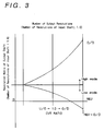
- the output shaft 5 is rotated in a forward (Lo) direction and a reverse (Rev) direction across a zero rotation. That is, when the output shaft 5 is rotated in the forward (advancing) direction based on the torque circulation, the belt type continuously variable transmission unit 11 transmits torque from the secondary pulley 9 to the primary pulley 7, whereas when the output shaft 5 is rotated in the backward (retracting) direction, the transmission unit 11 transmits torque from the primary pulley 7 to the secondary pulley 9.
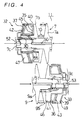
- the movable sheaves 7b, 9b are axially movably supported by the bosses 7c, 9c of the fixed sheaves 7a, 9a through ball splines 30, 31 and hydraulic servos 32, 33 are disposed on the back surfaces of these movable sheaves 9b, 9b and constitute the axial force actuating means for applying axial forces to the pulleys, respectively, as shown in FIG. 4.
- Both of the hydraulic servos 32, 33 have partition members 35, 36 fixed to the bosses 7c, 9c of the fixed sheaves, cylinder members 37, 39, drum members 40, 41 fixed to the back surfaces of the movable sheaves 7b, 9b and second piston members 42, 43.
- the partition members 35, 36 are engaged with the drum members 40, 41 in an oil tight state as well as the second piston members 42, 43 are engaged with the cylinder members 37, 39 and the partition members 35, 36 in an oil tight state to thereby constitute a double piston structure composed of first hydraulic chambers 45, 46 and second hydraulic chambers 47, 49, respectively.
- the first hydraulic chambers 45, 46 in the above hydraulic servos 32, 33 form piston surfaces on the back surfaces of the movable sheaves 7b, 9b, respectively and the piston surfaces have the same effective pressure-receiving areas on the primary side and the secondary side.
- oil passages 50, 51, 52, 53 are defined to the bosses 7c, 9c of the fixed sheaves 7c, 9c on the primary side and secondary side and communicate with the first hydraulic chambers 45, 46 and second hydraulic chambers 47, 49, respectively.
- a preloading spring 55 is contractedly disposed to the first hydraulic chamber 45 of the primary side hydraulic servo 32.
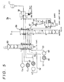
- the hydraulic control mechanism (means) 54 of this embodiment has a primary regulator valve 56, a ratio control valve 57, a down-shift relief valve 58, a manual valve (switching valve, selection means) 59 and a low/high control valve (low/high shifting means) 60.
- the hydraulic pressure from the oil pump 17 is properly regulated as well as switched and supplied to the first and second hydraulic chambers 45, 46, 47, 49 of the above hydraulic servos 32, 33, the low clutch (hydraulic servo) C L and high clutch (hydraulic servo) C H .
- a predetermined hydraulic pressure is supplied to the hydraulic chamber 45 of the primary side hydraulic servo 32 as well as a predetermined hydraulic pressure acts on both the first hydraulic chamber 46 and second hydraulic chamber 49 of the secondary side hydraulic servo 33 and further a hydraulic pressure acts on the low clutch C L to connect it. That is, in the low mode, the manual valve 59 is actuated to the position of the D range shown in FIG. 5 so as to cause a port d to communicate with a port e, a port f with a port g, a port h with a port i and a port k with a port l as well as a port j with a drain port Ex.
- the low/high control valve 60 is located at a low (L) position and switched and maintained to cause a port o to communicate with a port p, a port q with a port r, a port s with a port t, a port u with a port v and a port w with a port x as well as a port y with the drain port Ex.
- the hydraulic pressure from the output port c of the primary regulator valve 56 is supplied to the low clutch hydraulic servo C L through the ports d and e in the manual valve 59 located at the position of the D range (refer to FIG. 5) and further the ports o and p of the low/high control valve 60 and causes the clutch C L to be engaged.
- the above hydraulic pressure is supplied to the first hydraulic chamber 45 of the primary hydraulic servo 32 through the ports f and g of the manual valve and further the ports q and r of the low/high control valve 60.
- the down-shift relief valve 58 is located at a normal position where the port m communicates with the port n and the hydraulic pressure from the above output port c is supplied to the first hydraulic chamber 46 of the secondary hydraulic servo 33 through the ports m and n, the ports h and i of the manual valve 59 and the ports s and t of the low/high control valve 60.
- the hydraulic pressure from the above output port c is properly regulated by the ratio control valve 57 so that it becomes a hydraulic pressure corresponding to a target pulley ratio and the hydraulic pressure from the output port z is supplied to the second hydraulic chamber 49 of the hydraulic servo 33 through the ports k and l of the manual valve 59 and the ports w and x of the low/high control valve 60.
- the high clutch hydraulic servo C H is caused to communicate with the drain port Ex from the port y of the low/high control valve 60 and in a released state.
- the second hydraulic chamber 47 of the primary hydraulic servo 32 communicates with the drain port Ex through the ports u and v of the low/high control valve 60 and the port j of the manual valve 59.
- the low clutch C L is connected as well as the axial force caused by the secondary side hydraulic servo 33 in which a hydraulic pressure acts on both the first and second hydraulic chambers 46, 49 is made higher than the axial force caused by the primary side hydraulic servo 32 in which a hydraulic pressure acts on only the first hydraulic chamber 45 in the CVT unit 11.
- the opening/closing of the above ratio control valve 57 is properly adjusted in the state of the axial forces of both the pulleys 9, 7 corresponding to the torque transmitted from the secondary pulley 9 to the primary pulley 7.
- the hydraulic pressure of the second hydraulic chamber 49 of the secondary hydraulic servo 33 is regulated to thereby properly adjust the axial force caused by the hydraulic servo 33, so that a pulley ratio (torque ratio) is properly changed.
- a pulley ratio torque ratio
- the engine torque which is transmitted from the input shaft 3 to the carrier 19c of the planetary gear 19 through the low clutch C L and power transmission unit 26 is taken out from the output shaft 5 through the ring gear 19r while being regulated by the CVT unit 11 through the sun gear 19s based on the above predetermined pulley ratio.
- a predetermined hydraulic pressure is supplied to the first and second hydraulic chambers 45, 47 of the primary side hydraulic servo 32 as well as to the first hydraulic chamber 46 of the secondary side hydraulic servo 33 and further to the high clutch hydraulic servo C H as shown in FIG. 8.
- the port o communicates with the port y, the port q with the port t, the port s with the port r, the port x with the port v and the port w with the port u, respectively and the port p communicates with the drain port Ex as shown in FIG. 6.
- the hydraulic pressure output from the primary regulator valve 56 is supplied to the high clutch hydraulic servo C H through the ports d and e of the manual valve 59 and the ports o and y of the low/high control valve 60 to thereby cause the clutch C H to engage. Further, the above hydraulic pressure is supplied to the first hydraulic chamber 46 of the secondary hydraulic servo 33 through the ports f and g of the manual valve 59 and the ports q and t of the low/high control valve 60.
- the hydraulic pressure is supplied to the first hydraulic chamber 45 of the primary hydraulic servo 32 through the ports m and n of the down-shift relief valve 58, the ports h and i of the manual valve 59 and the ports s and r of the low/high control valve 60 and to the second hydraulic chamber 47 of the primary hydraulic servo 32 through the output port z of the ratio control valve 57 in which the hydraulic pressure is properly regulated, the ports k and l of the manual valve 59 and the ports w and u of the low/high control valve 60.
- the low clutch hydraulic servo C L is released by being caused to communicate with the drain port Ex from the port p of the low/high control valve 60 in this state.
- the second hydraulic chamber 49 of the secondary hydraulic servo 33 communicates with the drain port Ex through the ports x and v of the low/high control valve 60 and the port j of the manual valve 59.
- the high clutch C H is connected as well as the axial force caused by the primary side hydraulic servo 32 in which a hydraulic pressure is supplied to the first and second hydraulic chambers 45, 47 is made higher than the axial force caused by the secondary side hydraulic servo 33 in which a hydraulic pressure is supplied only to the first hydraulic chamber 46 in the CVT unit 11.
- above ratio control valve 57 is properly adjusted in the state of the axial force corresponding to the torque transmitted from the primary pulley 7 to the secondary pulley 9.
- the hydraulic pressure of the second hydraulic chamber 47 of the primary hydraulic servo 32 is regulated to thereby adjust the axial force caused by the primary hydraulic servo 32, so that a proper pulley ratio (torque ratio) can be obtained.
- the torque transmitted from an engine to the input shaft 3 is properly changed by the CVT unit 11 by being transmitted from the primary pulley 7 to the secondary pulley 9 and further taken out from the output shaft 5 through the high clutch C H .
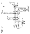
- a predetermined hydraulic pressure is supplied to the first and second hydraulic chambers 45, 57 of the primary side hydraulic servo 32 as well as to the first hydraulic chamber 46 of the secondary side hydraulic servo 33 and further to the low clutch hydraulic servo C L as shown in FIG. 8. That is, in the reverse range, the manual valve 59 is located at a reverse (R) range position and the low/high control valve 60 is located at the low position (L) as shown in FIG. 7. In this state, the port d communicates with the port e, the port f with the port i and the port k with the port j, respectively in the manual valve 59 and the port l communicates with the drain port Ex.
- the port o communicates with the port p, the port q with the port r, the port s with the port t, the port v with the port u and the port x with the port w, respectively in the low/high control valve 60 likewise the afore the low (L) mode and the port y communicates with the drain port Ex.
- the hydraulic pressure from the output port c of the primary regulator valve 56 is supplied to the low clutch hydraulic servo C L through the ports d and e of the manual valve 59 and the ports o and p of the low/high control valve 60 and further to the first hydraulic chamber 46 of the secondary hydraulic servo 33 through the ports f and i of the manual valve 59 and the ports s and t of the low/high control valve 60. Further, the above hydraulic pressure is supplied to the first hydraulic chamber 45 of the primary hydraulic servo 32 through the ports m and n of the down-shift relief valve 58, the ports h and g of the manual valve 59 and the ports q and r of the low/high control valve 60.
- the hydraulic pressure is properly regulated by the ratio control valve 57 and supplied from the output port z thereof to the second hydraulic chamber 47 of the primary hydraulic servo 32 through the ports k and j of the manual valve 59 and the ports v and u of the low/high control valve 60.
- the low clutch C L is connected as well as the axial force caused by the primary side hydraulic servo 32 in which a hydraulic pressure acts on the first and second hydraulic chambers 45, 47 is made higher than the axial force caused by the secondary side hydraulic servo 33 in which a hydraulic pressure acts only on the first hydraulic chamber 46 in the CVT unit 11.
- the state of an axial force corresponding to the torque transmitted from the primary pulley 7 to the secondary pulley 9 is achieved as well as the hydraulic pressure in the second hydraulic chamber 47 of the primary hydraulic servo 32 is regulated by the adjustment of the ratio control valve 57 to thereby adjust the axial force caused by the hydraulic servo 32, so that a proper pulley ratio can be obtained.
- both the low clutch C L and high clutch C H are released as well as a predetermined hydraulic pressure is supplied to the first hydraulic chambers 45, 46 of the primary side and secondary side hydraulic servos 32, 33 as shown in FIG. 8. That is, the port f communicates with the port g, the port h with the port i in the manual valve 59 and further the ports e, j, l communicate with the drain port Ex, respectively.
- the low/high control valve 60 is kept at the aforesaid low position L.
- the hydraulic pressure output from the primary regulator valve 56 is supplied to the first hydraulic chamber 45 of the primary hydraulic servo 32 through the ports f and g of the manual valve 59 and the ports q and r of the low/high control valve 60 as well as to the first hydraulic chamber 46 of the secondary hydraulic servo 33 through the ports m and n of the down-shift relief valve 58, the ports h and i of the manual valve 59 and the ports s and t of the low/high control valve 60.
- the hydraulic pressure of the high clutch hydraulic servo C H is released through the port y of the low/high control valve 60 and the drain port Ex
- the hydraulic pressure of the low clutch hydraulic servo C L is released through the ports p and o of the low/high control valve 60, the port e of the manual valve 59 and the drain port Ex
- the hydraulic pressure of the second hydraulic chamber 47 of the primary hydraulic servo 32 is released through the ports u and v of the low/high control valve 60, the port j of the manual valve 59 and the drain port Ex
- the hydraulic pressure of the second hydraulic chamber 49 of the second hydraulic servo 33 is released through the ports x and w of the low/high control valve 60, the port l of the manual valve 59 and the drain port Ex.
- a predetermined hydraulic pressure is supplied from the primary regulator valve 56 to the first hydraulic chambers 45, 46 of both the primary and secondary hydraulic servos 32, 33, respectively in the aforesaid respective positions D, N and R and the low (L) mode and high (H) mode, a predetermined axial force corresponding to the transmitted torque is secured so that a belt doe not slip.
- the regulated hydraulic pressure from the ratio control valve 57 is supplied to the second hydraulic chamber 47 or 49 of any one of the above hydraulic servos 32, 33, the ratio of the axial forces of both the pulleys 7, 9 is adjusted so that a speed changing operation is executed so as to obtain a predetermined pulley ratio.
- the down-shift relief valve 58 is switched to cause the port n to communicate with the drain port Ex.
- the hydraulic pressure supplied to the first hydraulic chamber 45 or 46 of both the hydraulic servos 32, 33 as described above is discharged through predetermined ports, the port n of the relief valve 58 and the drain port Ex and the hydraulic pressure in the hydraulic servo on which a high hydraulic pressure acts is made lower than the hydraulic pressure of the hydraulic servo on which a low hydraulic pressure acts.
- FIG. 9 Although primary and secondary side hydraulic servos 32, 33 of this embodiment shown in FIG. 9 have first and second hydraulic chambers 73 1 , 75 1 , 73 2 , 75 2 , respectively likewise those shown in FIG. 4, holes 70, 70 are defined to the partition members 35, 36 so as to simply increase pressure receiving areas.
- this embodiment constitutes a hydraulic actuator composed of substantially each one of hydraulic chambers 73, 75 which are supplied with hydraulic pressures from oil passages 71, 72, respectively and the hydraulic chambers 73, 75 of both the hydraulic servos 32, 33 have the same pressure-receiving areas.
- a preloading spring 55 is contractedly disposed to the first hydraulic chamber 75 1 of the secondary side hydraulic servo 33. As shown in FIG. 10 to FIG. 12.
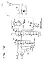
- control mechanism 54' has a primary regulator valve 56, a ratio control valve 57 constituting a secondary regulator valve and a down-shift relief valve 58 which are continuously disposed in series from an oil pump 17 and further a manual valve 59' and a low/high control valve 60' each having an oil passage structure different from that of the above embodiment.
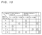
- the control mechanism 54' operates as shown in the operation table of FIG. 13
- a relatively low line pressure (P L - L) is supplied to the hydraulic chamber 73 of the primary hydraulic servo 32 from the ratio control valve 57, a relatively high line pressure (P L - H) is supplied to the hydraulic chamber 75 of the secondary hydraulic servo 33 from the primary regulator valve 56 and a line pressure is supplied to a low clutch hydraulic servo C L , as shown in FIG. 13.
- a port d communicates with a port e, a port f with a port i and a port h with a port g
- a port o communicates with a port p, a port q with a port t and a port s with a port r as well as a port y communicates with a drain port Ex, as shown in FIG. 10.
- the relatively high line pressure (P L - H) regulated by the primary regulator valve 56 is supplied to the low clutch hydraulic servo C L through the ports d and e of the manual valve 59' and the ports o and p of the low/high control valve 60' and further to the secondary hydraulic servo 33 through the ports m and n of the down-shift relief valve 58, the ports f and i of the manual valve '59 and the ports s and r of the low/high control valve 60'.
- the pressure output from the primary regulator valve 56 is further properly regulated by the ratio control valve (secondary regulator valve) 57 and the resulting regulated relatively low line pressure (P L - L) is supplied from the output port z thereof to the primary hydraulic servo 32 through the ports h and g of the manual valve 59' and the ports q and t of the low/high control valve 60'.
- the hydraulic pressure of a high clutch hydraulic servo C H is released through the port y and drain port Ex.
- a low clutch C L is connected as well as the axial force of a secondary pulley 9 caused by the secondary hydraulic servo 33 on which the relatively high line pressure P L - H acts is made higher than the axial force of a primary pulley 7 caused by the primary hydraulic servo 32 on which the relatively low line pressure P L - L acts in a CVT unit 11.
- This state corresponds to the low (L) mode in the D range where torque is transmitted from the secondary pulley 9 to the primary pulley 7 as well as since the axial force of the primary pulley 7 is adjusted by the proper pressure regulation effected by the ratio control valve 57 so that a pulley ratio (torque ratio) is properly changed.
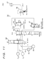
- the relatively high line pressure P L - H is supplied to the primary hydraulic servo 32 as well as the relatively low line pressure P L - L is supplied to the secondary hydraulic servo 33 and the line pressure is supplied to the high clutch hydraulic servo C H as shown in FIG. 13. That is, although the manual valve 59' is maintained at the D range position likewise the above case, since the low/high control valve 60' is switched to a high (H) position, the port o communicates with the port y and the port q with the port r and the port s with the port t, respectively, and further the port p communicates with the drain port Ex, as shown in FIG. 11.
- the relatively high regulated pressure (line pressure) P L - H from the primary regulator valve 56 is supplied to the high clutch hydraulic servo C H through the ports d and e of the manual valve 59' and the ports o and y of the low/high control valve 60' and further to the primary hydraulic servo 32 through the ports m and n of the down-shift relief valve 58, the ports f and i of the manual valve 59' and the ports s and t of the low/high control valve 60'.
- the relatively low regulated pressure (line pressure) P L - L obtained by further regulating the pressure output from the primary regulator valve 56 is supplied from the output port z thereof to the secondary hydraulic servo 33 through the ports h and g of the manual valve 59' and the ports q and r of the low/high control valve 60'.
- the hydraulic pressure of the low clutch hydraulic servo C L is released through the port p and drain port Ex.
- the high clutch C H is connected as well as the axial force of the primary pulley 7 caused by the primary hydraulic servo 32 on which the relatively high line pressure P L - H acts is made higher than the axial force of the secondary pulley 9 caused by the secondary hydraulic servo 33 on which the relatively low line pressure P L - L acts in the CVT unit 11.
- This state corresponds to the high (L) mode where torque is transmitted from the primary pulley 7 to the secondary pulley 9 as well as since the axial force of the secondary pulley 9 is adjusted by the proper pressure regulation effected by the ratio control valve 57 so that the pulley ratio (torque ratio) is properly changed.
- the relatively high line pressure P L - H acts on the primary hydraulic servo 32 and the relatively low line pressure P L - L acts on the secondary hydraulic servo 33 as well as the line pressure acts on the low clutch hydraulic servo C L as shown in FIG. 13. That is, the manual valve 59 is switched to a reverse (R) range position, the port d communicates with the port e, the port f with the port g and the port h with the port i and further the low/high control valve 60' is maintained at the aforesaid low (L) position, as shown in FIG. 12.
- the relatively high regulated pressure (line pressure) P L - H from the primary regulator valve 56 is supplied to the low clutch hydraulic servo C L through the ports d and e of the manual valve 59' and the ports o and p of the low/high control valve 60' as well as to the primary hydraulic servo 32 through the ports m and n of the down-shift relief valve 58, the ports f and g of the manual valve 59' and the ports q and t of the low/high control valve 60'.
- the relatively low regulated pressure (line pressure) P L - L from the ratio control valve 57 is supplied to the secondary hydraulic servo 33 through the port h and i of the manual valve 59' and the ports s and r of the low/high control valve 60'.
- the hydraulic pressure of the high clutch hydraulic servo C H is discharged from the port y to the drain port Ex.
- the low clutch C L is connected as well as the relatively high hydraulic pressure P L - H based on the primary regulator valve 56 acts on the primary hydraulic servo 32 and the relatively low hydraulic pressure P L - L based on the ratio control valve 57 acts on the secondary hydraulic servo 33 in the CVT unit 11.
- the axial force of the primary pulley 7 is made higher than that of the secondary pulley 9 in correspondence with the torque transmission as well as the axial force of the secondary pulley 9 is adjusted by the pressure regulation effected by the ratio control valve 57 so that the pulley ratio is properly changed.
- the relatively low hydraulic pressure P L - L acts on the primary hydraulic servo 32 as well as the relatively low hydraulic pressure P L - L acts on the secondary hydraulic servo 33 as shown in FIG. 13. That is, since the manual valve 59' is switched to the neutral or parking position, the port e communicates with the drain port Ex as well as the port h communicates with the ports g and i and the low/high control valve 60' is maintained at the aforesaid low (L) position.
- the hydraulic pressure from the output port z of the ratio control valve 57 is supplied from the port h of the manual valve 59' to the primary hydraulic servo 32 through the port g and the ports q and t of the low/high control valve '60 as well as to the secondary hydraulic servo 33 through the port i and the ports s and r of the low/high control valve 60'.
- the hydraulic pressure of the high clutch hydraulic servo C H is discharged from the port y of the low/high control valve 60' to the drain port Ex and the hydraulic pressure of the low clutch hydraulic servo C L is discharged through the ports p and o of the low/high control valve 60', the port e of the manual valve 59' and the drain port Ex in this state.
- both the low and high clutches C L , C H are shut off as well as the same hydraulic pressure acts on the primary hydraulic servo 32 and secondary hydraulic servo 33 having the same pressure-receiving areas from the ratio control valve 57 so that approximately the same axial forces act on both the primary and secondary pulleys 7, 9.
- the down-shift relief valve 58 is switched to cause the port n to communicate with the drain port Ex, thus the hydraulic pressure of the hydraulic servo on which a high hydraulic pressure acts is made lower than the hydraulic pressure of the hydraulic servo on which a low hydraulic pressure acts.
- the control mechanism 541 is applied to a so-called double chamber type control mechanism having the primary and secondary hydraulic servos 32, 33 shown in FIG 4, that is, the first and second hydraulic chambers 45, 46, 47, 49.
- a primary regulator valve 56, a ratio control valve 57, a down-shift relief valve 58 and a manual valve 59 are used which are similar to those of the embodiments shown in FIG. 5 to FIG. 7, a low/high control valve 601 is composed of a simple 2-position-switching solenoid valve with 4 ports.
- a pilot oil passage 77a is branched from an oil passage 77 from the port y of the low/high control valve 601 to a high clutch servo C H and there is provided a switching valve 79 which is switched by a pilot pressure.
- a port o communicates with a port p and a port y with a drain port Ex.
- the switching valve 79 is located at the illustrated position in the state that the oil passage 77 communicates with the drain port Ex, a port q with a port r, a port s with a port t, a port u with a port v and a port w with a port x.
- the manual valve 59 is arranged in the D range position such that the ratio pressure from the ratio control valve 57 is introduced to an oil passage (2) and an oil passage (1) communicates with the drain port Ex.
- the clutch pressure P C from the manual valve 59 is supplied to a low clutch hydraulic servo C L through the ports o and p of the low/high control valve 601 and the first and second line pressures P L 1, P L 2 from the manual valve are supplied to the first hydraulic chamber 45 of the primary hydraulic servo 32 and the first hydraulic chamber 46 of the secondary hydraulic servo 33 through the ports q, r, s, t of the switching valve 79.
- the ratio pressure from the manual valve is supplied to the second hydraulic chamber 49 of the secondary hydraulic servo 33 through the oil passage (2) and the ports w and x of the switching valve 79 and the hydraulic pressure of the second hydraulic chamber 47 of the primary hydraulic servo 32 communicates with the drain port Ex of the manual valve through the ports u and v and the oil passage (1).
- the low clutch C L is connected as well as the axial force of the secondary pulley 9 is made higher than that of the primary pulley 7 by the ratio pressure acting on the second hydraulic chamber 49 of the secondary hydraulic servo 33 in accordance with the direction in which torque is transmitted in the CVT unit 11 likewise the above-mentioned.
- the port o communicates with the port y as well as the port p with the drain port Ex. Since the switching valve 79 is switched by the pilot pressure from the oil passage 77a in the state that the clutch pressure P C is supplied to the oil passage 77 through the ports o and y, the port q communicates with the port t, the port s with the port r, the port x with the port v and the port w with the port u.
- the clutch pressure P C is supplied to the high clutch hydraulic servo C H through the ports o and y of the low/high control valve 60 1 and the line pressures P L 1 and P L 2 are supplied to the first hydraulic chamber 46 of the secondary hydraulic servo 33 through the ports q and t of the switching valve 79 as well as to the first hydraulic chamber 45 of the primary hydraulic servo 32 through the ports s and r.
- the ratio pressure from the manual valve 59 is supplied to the second hydraulic chamber 47 of the primary hydraulic servo 32 through the oil passage (2) and the ports w and u and the hydraulic pressure of the second hydraulic chamber 49 of the secondary hydraulic servo 33 is discharged from the drain port of the manual valve 59 through the ports x and v and oil passage (1).
- the high clutch C H is connected as well as the axial force of the primary pulley 7 caused by the primary hydraulic servo 32 in which the ratio pressure acts on the second hydraulic chamber 47 is made higher than that of the secondary pulley 9 in accordance with the direction in which torque is transmitted in the CVT unit 11.
- the manual valve 59 is switched and the low/high control valve 60 1 is maintained at the low (L) position as shown in FIG. 7. Therefore, the switching valve 79 is maintained at a lower position in the drawing in this state likewise the above-mentioned. Further, the ratio pressure is supplied to the oil passage (1) by switching the switching valve 79 as well as the oil passage (2) communicates with the drain port Ex.
- the clutch pressure P C is supplied to the low clutch hydraulic servo C L through the ports o and p and the first and second line pressures are supplied to the first hydraulic chamber 5 of the primary hydraulic servo through the ports q and r as well as to the first hydraulic chamber 46 of the secondary hydraulic servo through the ports s and t.
- the ratio pressure through the manual valve 59 is supplied to the second hydraulic chamber 47 of the primary hydraulic servo through the oil passage (1) and the ports v and u and the hydraulic pressure of the second hydraulic chamber of the secondary hydraulic servo is discharged from the drain port Ex of the manual valve 59 through the ports x and w and the oil passage (2).
- the low clutch C L is connected as well as the axial force of the primary pulley 7 caused by the primary hydraulic servo 32 in which the ratio pressure acts on the second hydraulic chamber 47 is made higher than that of the secondary pulley 9 in accordance with the direction in which torque is transmitted in the CVT unit 11.
- the control mechanism 542 acts on a so-called double regulator type control mechanism having the primary and secondary hydraulic servos 32, 33 shown in FIG 9, that is, each one of a hydraulic chambers 73 and 75 having the same pressure-receiving areas for supplying different hydraulic pressures, respectively.
- a primary regulator valve 56, a ratio control valve (secondary regulator valve) 57, a down-shift relief valve 58 and a manual valve 59' are used which are similar to those of the embodiments shown in FIG. 10 to FIG.
- a low/high control valve 60 1 is composed of a simple 2-position-switching solenoid valve with 4 ports as well as a switching valve 80 is provided which can switch a hydraulic pressure from the port y of the valve 60 1 to the high clutch hydraulic servo C H as a pilot pressure.
- the clutch pressure P C from the manual valve 59' is supplied to the low clutch hydraulic servo C L through the ports o and p of the low/high control valve 60 1 , the relatively low line pressure P L - L from the oil passage (3) is supplied to the primary hydraulic servo 32 through the ports q and t of the switching valve 80 and the relatively high line pressure P L - H from the oil passage (4) is supplied to the hydraulic servo 33 through the ports s and r.
- the port o communicates with the port y as well as the port p with the drain port Ex. Since the switching valve 80 is switched by the pilot pressure from the oil passage 77a in the state that the clutch pressure P L is supplied to the oil passage 77 through the ports o and y, the port q communicates with the port r and the port s with the port t.
- the clutch pressure P C is supplied to the high clutch hydraulic servo C H
- the relatively low line pressure P L - L from the oil passage (3) is supplied to the secondary hydraulic servo 33 through the ports q and r of the switching valve 80
- the relatively high line pressure P L - H from the oil passage (4) is supplied to the primary hydraulic servo 32 through the ports s and t.
- the high clutch C H is connected as well as the axial force of the primary pulley 7 caused by the hydraulic servo 32 on which a somewhat high line pressure acts is made higher than that of the secondary pulley 9 in accordance with the direction in which torque is transmitted in the CVT unit 11.
- the switching valve 80 is maintained at a lower position of the drawing in this state likewise the above-mentioned.
- the switching of the manual valve 59' causes the relatively high line pressure P L - H from the primary regulator valve 56 to be introduced to the oil passage (3) and the relatively low pressure line pressure P L - L to be introduced to the oil passage (4) from the ratio control valve 57. Further, the relatively low line pressure P L - L from the ratio control valve 57 is introduced to the oil passage (4).
- the clutch pressure C L is supplied to the low clutch hydraulic servo C L through the ports o and p, the somewhat high line pressure P L - H from the oil passage (3) is supplied to the primary hydraulic servo 32 through the ports q and t and the somewhat low line pressure P L - L from the oil passage (4) is supplied to the secondary hydraulic servo 33 through the ports s and r.
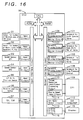
- FIG. 16 is a block diagram of an electronic control unit (EUC) 90, wherein numeral 91 denotes a sensor disposed to the continuously variable transmission 1 for detecting the r.p.m. of the input shaft 2 thereof, numeral 92 denotes a sensor for detecting the r.p.m. of the secondary pulley 9 of the CVT unit 11, numeral 93 denotes a vehicle speed sensor for detecting the r.p.m. of the output shaft 5 of the continuously variable transmission and numeral 94 denotes a similar vehicle speed sensor also used for a signal of a speed meter as well as used as a backup device when the vehicle speed sensor 93 fails.
- EUC electronice control unit
- Numeral 95 denotes a sensor for detecting where of the respective shift positions P, R, N, D the shift lever or the manual valve of the continuously variable transmission is located
- numeral 96 denotes a sensor composed of a potentiometer disposed in the engine for detecting a throttle opening
- numeral 97 denotes a sensor disposed in the throttle opening sensor 96 for detecting whether an accelerator is in an entirely closed state or not.
- the signals from the above respective sensors are fetched by a CPU, a ROM or a RAM through an input processing circuit and an input interface circuit, respectively.
- Numeral 101 denotes a solenoid for the low/high control valve 60 for switching to the low (L) mode and the high (H) mode and the solenoid executes ON/OFF operation.
- Numeral 102 denotes a solenoid used for the down-shift relief valve 58 for draining a high voltage side circuit and composed of a duty or linear solenoid.
- Numeral 103 denotes a solenoid used for the ratio control valve 57 for regulating a speed changing hydraulic pressure and composed of a duty or linear solenoid.
- Numeral 105 denotes a solenoid used for the primary regulator valve 56 for controlling a line pressure and composed of a linear solenoid.
- the above respective solenoids are driven through a solenoid drive circuit 106 for generating a predetermined voltage or output based on the signals from an output interface circuit, respectively and the operations of the respective solenoids are checked by a monitor circuit 107 to determine their failure as well as they determine their failure by themselves.
- Numeral 109 denotes an electronic control unit for controlling the engine and numeral 110 denotes a circuit for issuing a signal for temporarily reducing torque generated by the engine by delaying an ignition timing angle, shutting-off fuel supply etc. to ease shock caused in speed change.
- Numeral 111 denotes a processing circuit for inputting engine r.p.m.
- Numeral 112 denotes a checker composed of an indicator lamp and the like for outputting the result of self-diagnosis when the electronic control unit 90 fails and numeral 113 denotes a circuit for outputting the result of the self-diagnosis in the above failure.
- Numeral 115 denotes a display unit such as low (L) mode and high (H) mode display lamps and the like for displaying the state of the continuously variable transmission and numeral 116 denotes a drive circuit for driving the display unit 115.
- FIG. 17 is a general flowchart of the continuously variable transmission, wherein all the steps are initialized at the beginning of calculation at step S1.
- r.p.m. is calculated based on the signals from the above r.p.m. sensors 91, 92 and 93.
- the signal from a neutral start switch is processed and a shifted position is read at step S3 and a throttle opening is calculated at step S4.
- step S6 whether the manual valve is located in the reverse (R) range or not is determined based on the above step S3 at step S5, and when the determination is YES, an R range control to be described later will be executed (step S6).
- step S7 whether the D range is selected or not is determined (step S7), and when the D range is selected, it is determined whether or not a current vehicle speed V is equal to or less than a predetermined vehicle speed V1 (for example, 5 Km/h) (step S8).
- a current vehicle speed V is equal to or less than the vehicle speed
- start control is executed (step S9), whereas it is greater than the predetermined vehicle speed
- line pressure control is executed to set a line pressure depending upon whether the low (L) mode is selected or the high (H) mode is selected, the throttle opening and the pulley ratio (step S10).
- a target engine r.p.m. is read and determined from the map of a preset optimum fuel consumption curve based on the throttle opening at step S11.
- step S12 which of down-shift and up-shift must be selected or otherwise the current state must be maintained is determined by comparing the current engine r.p.m. with the above target engine r.p.m. (step S12) and the down-shift control (step S13) or the up-shift control (step S14) to be described later will be executed respectively.
- FIG. 18 is a flowchart showing a subroutine of the reverse (R) range control, wherein whether a vehicle travels forward or not is determined first from the pulley ratio and vehicle speed at step S15.
- a predetermined vehicle speed V2 for example, 5 Km/h
- control for prohibiting reverse operation is executed by, for example, the release of both the low clutch C L and low clutch C L , or the like (step S17), whereas when the vehicle speed is smaller than the predetermined vehicle speed, neutral (N) control is executed (step S18).
- the axial forces of the primary pulley 7 and secondary pulley 9 are controlled to be substantially equalized. Otherwise, at least the difference between the axial force of the primary pulley and the axial force of the secondary pulley is set to a value smaller than the difference of the axial forces of both the pulleys which is determined by the input torque of the CVT and the pulley ratio at the time when output torque is in a positive direction within the range in which the relative relationship in magnitude of the axial forces is not reversed or to a value smaller than the difference of the axial forces of the primary and secondary pulleys which is determined by the input torque of the CVT unit and the pulley ratio at the time when the output torque is in a negative direction within the range in which the relative relationship in magnitude of the axial forces is not reversed.
- the CVT unit 11 is converged by itself so that the output from the output shaft 5 is made to zero regardless of the r.p.m. of the output shaft and stably maintained at the neutral position where the r.p.m. of the output shaft 5 is made to zero.
- the aforesaid neutral control is described in the specification and drawings of Japanese Patent Application Laid-Open No. 7-66234 in detail and the content thereof is applicable to this embodiment as it is.
- the current vehicle speed V is compared with the predetermined vehicle speed V1 (for example, 5 Km/h) (step S19) and when the current vehicle speed V is smaller than the predetermined vehicle speed V1, start control is executed (step S20), whereas when the current vehicle speed V is greater than the predetermined vehicle speed V1, line pressure control is executed to set a line pressure based on the throttle opening and pulley ratio (step S21). Further, a target engine r.p.m. is determined by reading the map likewise the above-mentioned (refer to step S10) at step S22.
- V1 for example, 5 Km/h
- step S23 any of up-shift, down-shift and the maintenance of the current state is determined likewise the above step S12 (step S23) and the down-shift control (step S24) or the up-shift control (step S25) to be described later will be executed, respectively.
- the CVT unit 11 is located at the O/D end and the speed increasing rotation transmitted from the CVT unit to the sun gear 19s is synthesized with the constant rotation transmitted from the power transmission unit 26 to the carrier 19c by the planetary gear 19 and a reverse rotation is taken out from the output shaft 5 integrally arranged with the ring gear 19r in the above reverse (R) control.
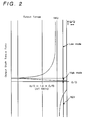
- the torque output from the CVT unit 11 is reversed across the neutral position (output from the output shaft 5 is zero) based on the torque circulation and power is transmitted from the primary pulley 7 to the secondary pulley 9 in the CVT unit 11 as shown in FIG. 2.
- the manual valves 59, 59' are located at the reverse (R) position as shown in FIG. 7, FIG.
- FIG. 8 FIG. 12, FIG. 13, FIG. 14, FIG. 15 and the hydraulic pressure of the hydraulic servo 32 is set higher than that of the hydraulic servo 33 when positive torque is transmitted (transmitted to the engine and wheels). Consequently, the axial force Fpr of the primary pulley 7 is made higher than the axial force Fsr of the secondary pulley 9 as shown in FIG. 23 so that the relationship of axial forces in coincidence with the aforesaid torque transmission direction is established. In this state, the axial forces Fpr and Fsr of both the pulleys 7, 9 are properly changed so as to properly change a speed by the proper control of the ratio control valve 57.
- FIG. 19 is a flowchart showing up-shift control in the D range shown at step S14, wherein it is determined whether a speed is to be changed from the low (L) mode to the high (H) mode to be described later at step S26. Note, R range control is not executed at step S26. Further, the difference between a current engine r.p.m. and a target engine r.p.m. and the acceleration of the difference are calculated (step S27) and a speed changing speed is calculated based on the calculation (step S28), whereby the application control of the ratio control valve 57 is executed (step S29).
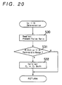
- FIG. 20 is a subroutine showing the determination of Lo ⁇ Hi at the above step S26.
- a pulley ratio is calculated based on the signals from the r.p.m. sensors 91, 92 of the primary pulley 7 and secondary pulley 9. Then, it is determined whether the pulley ratio is within the range in which a speed change from the low mode to the high mode is permitted (step S31) and when the pulley ratio is within the range, the low/high control valve 60 is switched to thereby change the engagement with the low clutch C L to the engagement with the high clutch C H (step S32).
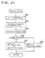
- FIG. 21 is a flowchart showing down-shift control shown at step S13, wherein it is determined at step S33 whether a speed change from the high (H) mode to the low (L) mode to be described later is to be executed or not (this is not executed in the R range control). Further, the difference between a current engine r.p.m. and a target engine r.p.m. and the acceleration of the difference are calculated (step S34) and a speed changing speed is calculated based on the calculation (step S35). Further, whether down-shift is power-off down-shift or not is determined based on the signals from the throttle opening sensor 96 and idle switch 97 (step S36).
- step S37 when a coast state is achieved by power-off, that is, by releasing depression of an accelerator pedal, or the like, the ratio control valve 57 is controlled as well as the down-shift relief valve 58 is controlled (step S37), whereas when down-shift is executed in a power-on state, that is, in an accelerated state in which the accelerator pedal is abruptly depressed, the ratio control valve 57 is controlled (step S38).
- the coast state is in a negative torque state in which torque is transmitted from the wheels to the engine as shown at step S37.
- the relative relationship in magnitude between the axial force Fp' (Fpr') of the primary pulley 7 and the axial force Fs' (Fsr') of the secondary pulley 9 is reversed from the axial forces Fp, Fs (Fpr, Fsr) in a positive torque (engine wheels) state shown by the solid lines of FIG. 23, as shown by the dash lines of the drawing.
- the down-shift relief valve 58 is drained in the double chamber type control mechanism 54 shown in FIG.
- step S38 down shift control executed at step S38 when power is turned on will be described. Since the ratio control valve 57 is controlled in a pressure reducing direction in the double chamber type control mechanism 54 shown in FIG. 5, the hydraulic pressure of the secondary hydraulic servo 33 is made relatively smaller than that of the primary hydraulic servo 32, whereas since the ratio control valve 57 is controlled in a pressure increasing direction in the double regulator type control mechanism 54' shown in FIG. 10, the hydraulic pressure of the secondary hydraulic servo 33 is made relatively smaller than that of the primary hydraulic servo 32.
- FIG. 22 shows a subroutine for determining Hi ⁇ Lo at the above step S33.
- the low/high control valve 60 is switched so as to change the engagement from the high clutch C H to the low clutch C L (step S42).
- the speed is changed between the low (L) mode and high (H) mode by the change of engagement of the low clutch C L and high clutch C H executed at the above steps S32 and S42.
- the low mode a positive rotation is taken out from the output shaft 5 by the aforesaid synthesization of both the rotations of the power transmission unit 26 and CVT unit 11 executed by the planetary gear 19.
- power is transmitted from the secondary pulley 9 to the primary pulley 7 by the torque circulation in the CVT unit 11.
- the high mode since the rotation output from the CVT unit 11 is transmitted to the output shaft 5 as it is, power is transmitted from the primary pulley 7 to the secondary pulley 9 in the CVT unit 11.
- the hydraulic pressures of the primary hydraulic servo 32 and secondary hydraulic servo 33 are switched by switching the low/high control valves 60, 60' and 60 1 as shown in FIG. 6, FIG. 11, FIG. 14 and FIG. 15.
- the axial force FS of the secondary pulley 9 is made higher than the axial force FP of the primary pulley 7 in the low mode and the axial force of the primary pulley is made higher than that of the secondary pulley in the high mode in order to coincide with the above direction of power transmission.
- the above description relates to the transmission of positive torque and this is reversed in the transmission of negative torque by the down-shift relief valve as described above.
- FIG. 24 shows an embodiment using a dual pinion planetary gear 19.
- the ring gear 19r of the planetary gear can be coupled with the input shaft 3 through gears 130, 131 and the low clutch C L (first rotary element), the sun gear 19s thereof can be coupled with the secondary pulley 9 through gears 132, 133 (second rotary element), the carrier 19c thereof can be coupled with the output shaft 5 (third rotary element) and the ring gear 19r can be coupled with the sun gear 19s through the high clutch C H . Then, the ring gear 19r and sun gear 19s are rotated in the same direction.
- the third rotary element may be composed of the sun gear in place of the carrier and the first and second rotary elements may be composed of the carrier, the sun gear and the ring gear which do not serve as the third rotary element, respectively.
- the engine torque from the input shaft 3 is transmitted to the ring gear 19r of the planetary gear 19 through the low clutch C L and gears 131, 130 as well as to the sun gear 19s through the CVT unit 11 and gears 133, 132 in the low mode (Lo) as shown in the graph showing a speed of FIG. 24(b).
- torque circulation is caused by the planetary gear 19 likewise the above embodiment and an output is applied from the carrier 19c to the output shaft 5 in an increasing/decreasing direction opposite to that of the CVT unit 11 with the secondary pulley 9 serving as a driving side and the primary pulley 7 serving as a driven side in the CVT unit 11.
- the rotation of the carrier 19c is a reversed, that is, made to a reverse (Rev) rotation as well as the direction in which torque is transmitted from the CVT unit 11 is reversed.
- the high mode (Hi) the engine torque from the output shaft 5 is transmitted to a shaft 135 through the CVT unit 11 and gears 133, 135 as well as the planetary gear 19 is integrally rotated by the connection of the high clutch C H in the high mode, thus the speed changing torque of the above shaft 135 is transmitted to the output shaft 5 as it is in the CVT unit.
- the sun gear 19s of a single pinion planetary gear 19 is coupled with the input shaft 3 through the chain 22 and the low clutch C L (first rotary element), the ring gear 19r thereof is coupled with the secondary pulley 9 through the gears 132, 133 (second rotary element) and the carrier 19c thereof is coupled with the differential gear unit 25 through the output shaft 5 and the gear 21 and gear 24 (third rotary element). Then, the sun gear 19s and the carrier 19c are rotated in a reverse direction.
- the first rotary element may be composed of the ring gear and the second rotary element may be composed of the sun gear.
- the engine rotation from the input shaft 3 is transmitted to the sun gear 19s of the planetary gear 19 through the low clutch C L and chain 22 as well as to the ring gear through the CVT unit 11 and gears 133, 132 and both the rotations are synthesized and taken out from the output shaft 5 through the carrier 19c as shown in the graph showing a speed of FIG. 25(b).
- torque circulation is caused likewise the above-mentioned as well as the rotation is output from the output shaft 5 with the positive to reverse change of its rotational direction.
- a dual pinion planetary gear 19 is used by modifying the embodiment shown in FIG. 25. That is, the sun gear 19s of the dual pinion planetary gear 19 is coupled with the input shaft 3 through the chain 22 and low clutch C L (first rotary element), the carrier 19c thereof is coupled with the secondary pulley 9 through the gears 132, 133 (second rotary element), the ring gear 19r thereof is coupled with the differential gear unit 25 through the output shaft 5 and gears 21, 24 (third rotary element). Then, the sun gear 19s and carrier 19c are rotated in a reverse direction.
- the first rotary element may be composed of the carrier and the second rotary element may be composed of the sun gear.
- the engine rotation from the input shaft 3 is transmitted to the sun gear 19s of the dual planetary gear 19 through the low clutch C L and chain 22 as well as to the carrier 19c through the CVT unit 11 and gears 133, 132, then both the rotations are synthesized and taken out from the output shaft 5 through the carrier 19c as shown in the graph showing a speed of FIG. 26(b).
- torque circulation is caused likewise the above-mentioned as well as the rotation is output from the output shaft 5 with the positive to reverse change of its rotational direction.
Landscapes
- Engineering & Computer Science (AREA)
- General Engineering & Computer Science (AREA)
- Mechanical Engineering (AREA)
- Control Of Transmission Device (AREA)
- Transmission Devices (AREA)
Applications Claiming Priority (9)
| Application Number | Priority Date | Filing Date | Title |
|---|---|---|---|
| JP66234/95 | 1995-03-24 | ||
| JP06623495A JP3612773B2 (ja) | 1995-03-24 | 1995-03-24 | 無段変速機 |
| JP6623495 | 1995-03-24 | ||
| JP12870295 | 1995-05-26 | ||
| JP12870195A JP3498423B2 (ja) | 1995-05-26 | 1995-05-26 | 無段変速機 |
| JP128701/95 | 1995-05-26 | ||
| JP128702/95 | 1995-05-26 | ||
| JP12870195 | 1995-05-26 | ||
| JP12870295A JP3613641B2 (ja) | 1995-05-26 | 1995-05-26 | 無段変速機 |
Publications (3)
| Publication Number | Publication Date |
|---|---|
| EP0733831A2 true EP0733831A2 (de) | 1996-09-25 |
| EP0733831A3 EP0733831A3 (de) | 1997-12-10 |
| EP0733831B1 EP0733831B1 (de) | 2002-01-09 |
Family
ID=27299058
Family Applications (2)
| Application Number | Title | Priority Date | Filing Date |
|---|---|---|---|
| EP96104524A Expired - Lifetime EP0733831B1 (de) | 1995-03-24 | 1996-03-21 | Stufenloses Getriebe |
| EP96104523A Expired - Lifetime EP0733830B1 (de) | 1995-03-24 | 1996-03-21 | Stufenloses Getriebe |
Family Applications After (1)
| Application Number | Title | Priority Date | Filing Date |
|---|---|---|---|
| EP96104523A Expired - Lifetime EP0733830B1 (de) | 1995-03-24 | 1996-03-21 | Stufenloses Getriebe |
Country Status (3)
| Country | Link |
|---|---|
| US (2) | US5690576A (de) |
| EP (2) | EP0733831B1 (de) |
| DE (2) | DE69618367T2 (de) |
Cited By (1)
| Publication number | Priority date | Publication date | Assignee | Title |
|---|---|---|---|---|
| US10672207B2 (en) | 2017-01-20 | 2020-06-02 | Polaris Industries Inc. | Diagnostic systems and methods of a continuously variable transmission |
Families Citing this family (53)
| Publication number | Priority date | Publication date | Assignee | Title |
|---|---|---|---|---|
| DE69626762D1 (de) * | 1995-12-15 | 2003-04-24 | Aisin Aw Co | Stufenloses Getriebe |
| JPH09177928A (ja) * | 1995-12-26 | 1997-07-11 | Aisin Aw Co Ltd | 無段変速機 |
| DE19654695B4 (de) * | 1995-12-30 | 2012-01-19 | Hyundai Motor Co. | Stufenloses Getriebe |
| NL1002245C2 (nl) * | 1996-02-05 | 1997-08-07 | Doornes Transmissie Bv | Continu variabele transmissie. |
| US6146308A (en) * | 1996-10-03 | 2000-11-14 | Aisin Aw Co., Ltd. | Creep torque control of infinitely variable transmission |
| JP3475678B2 (ja) * | 1996-10-09 | 2003-12-08 | アイシン・エィ・ダブリュ株式会社 | 無段変速機 |
| US5803859A (en) * | 1997-05-23 | 1998-09-08 | General Motors Corporation | Powertrain with planetary gearing and a continuously variable ratio unit |
| US5803858A (en) * | 1997-05-23 | 1998-09-08 | General Motors Corporation | Powertrain transmission with torque converter planetary gearing and a continuously variable transmission unit |
| DE19728611A1 (de) * | 1997-07-04 | 1999-02-04 | Zahnradfabrik Friedrichshafen | Stufenloses Getriebe |
| JP3796916B2 (ja) * | 1997-08-25 | 2006-07-12 | マツダ株式会社 | トロイダル式無段変速機の制御装置 |
| DE19943332A1 (de) * | 1999-09-10 | 2001-03-15 | Zahnradfabrik Friedrichshafen | Verfahren zur Regelung der Fahrzeugbeschleunigung für ein Kraftfahrzeug mit einem stufenlosen Automatgetriebe |
| IL141094A0 (en) | 2001-01-25 | 2002-02-10 | Ran Siman Tov | Continuous variable transmission |
| DE10302992A1 (de) * | 2002-02-07 | 2003-10-16 | Luk Lamellen & Kupplungsbau | Verfahren zum Regeln der Übersetzung eines leistungsverzweigten automatischen Getriebes sowie leistungsverzweigtes automatisches Getriebe |
| CN1578890B (zh) * | 2002-09-30 | 2010-05-26 | 乌尔里克·罗斯 | 传动机构 |
| US6986725B2 (en) * | 2002-11-01 | 2006-01-17 | Eaton Corporation | Continuously variable stepped transmission |
| GB0300419D0 (en) * | 2003-01-09 | 2003-02-05 | Torotrak Dev Ltd | Continuously variable transmission and method of controlling regime change therein |
| WO2004068003A1 (ja) * | 2003-01-29 | 2004-08-12 | Honda Motor Co., Ltd. | 無段変速機の故障判定装置および発進クラッチの故障判定装置 |
| GB0501763D0 (en) * | 2005-01-28 | 2005-03-02 | Torotrak Dev Ltd | Powertrain control method and system |
| US7473202B2 (en) * | 2005-04-15 | 2009-01-06 | Eaton Corporation | Continuously variable dual mode transmission |
| JP2006329338A (ja) * | 2005-05-26 | 2006-12-07 | Nissan Motor Co Ltd | 分流式無段変速機 |
| CA2976893C (en) | 2005-12-09 | 2019-03-12 | Fallbrook Intellectual Property Company Llc | Continuously variable transmission |
| EP1811202A1 (de) | 2005-12-30 | 2007-07-25 | Fallbrook Technologies, Inc. | Stufenloses Getriebe |
| US7882762B2 (en) * | 2006-01-30 | 2011-02-08 | Fallbrook Technologies Inc. | System for manipulating a continuously variable transmission |
| EP2002154B1 (de) * | 2006-03-14 | 2013-10-02 | Fallbrook Intellectual Property Company LLC | Rollenschieber für moped |
| WO2007106874A2 (en) * | 2006-03-14 | 2007-09-20 | Autocraft Industries, Inc. | Improved wheelchair |
| US20100174456A1 (en) * | 2006-08-23 | 2010-07-08 | S.O.E. Technologies Inc. | Mechanical cvt drive train and control method for earth working vehicle |
| US7824308B2 (en) * | 2007-09-06 | 2010-11-02 | Eaton Corporation | Methods for shifting a vehicle transmission |
| US7789795B2 (en) * | 2007-10-17 | 2010-09-07 | Eaton Corporation | Method for controlling a vehicle powertrain having step ratio gearing and a continuously variable transmission to achieve optimum engine fuel economy |
| US8996263B2 (en) | 2007-11-16 | 2015-03-31 | Fallbrook Intellectual Property Company Llc | Controller for variable transmission |
| RU2474500C2 (ru) * | 2008-04-14 | 2013-02-10 | Хонда Мотор Ко., Лтд. | Привод для гибридного транспортного средства |
| KR101178501B1 (ko) | 2009-04-20 | 2012-09-03 | 최태수 | 무단 변속기의 전후진 변속시스템 |
| US8574110B2 (en) * | 2010-08-02 | 2013-11-05 | Ford Global Technologies, Llc | Transmission producing stepless variable speed ratios |
| EP2853776B1 (de) * | 2012-05-23 | 2019-10-09 | Toyota Jidosha Kabushiki Kaisha | Getriebevorrichtung für ein fahrzeug |
| US9371896B2 (en) * | 2012-05-23 | 2016-06-21 | Toyota Jidosha Kabushiki Kaisha | Power transmission unit for vehicle |
| DE112014005592A5 (de) * | 2013-12-09 | 2016-11-03 | Schaeffler Technologies AG & Co. KG | CVT-Antriebsstrang |
| WO2015151061A2 (en) * | 2014-04-03 | 2015-10-08 | Toyota Jidosha Kabushiki Kaisha | Control system for vehicle |
| US9377084B2 (en) * | 2014-07-31 | 2016-06-28 | GM Global Technology Operations LLC | Automated manual transmission with dynamic torque transfer device |
| US9546719B2 (en) * | 2014-11-05 | 2017-01-17 | GM Global Technology Operations LLC | Multi-mode transmission for vehicle powertrain system |
| WO2016172013A1 (en) * | 2015-02-14 | 2016-10-27 | Armin Tay | Maximum axial position changing rpm methods |
| JP2017031897A (ja) * | 2015-08-03 | 2017-02-09 | 株式会社クボタ | 作業車 |
| CN105090552B (zh) * | 2015-09-21 | 2018-01-09 | 常州伟泰科技股份有限公司 | 一种流体分度输送机构 |
| US10047861B2 (en) | 2016-01-15 | 2018-08-14 | Fallbrook Intellectual Property Company Llc | Systems and methods for controlling rollback in continuously variable transmissions |
| US9970521B1 (en) | 2016-02-26 | 2018-05-15 | Rodney J. Cook and successors in trust | Infinitely variable transmission |
| US10023266B2 (en) | 2016-05-11 | 2018-07-17 | Fallbrook Intellectual Property Company Llc | Systems and methods for automatic configuration and automatic calibration of continuously variable transmissions and bicycles having continuously variable transmissions |
| WO2018169521A1 (en) * | 2017-03-14 | 2018-09-20 | Albert Six | Two way transmission |
| US11215268B2 (en) | 2018-11-06 | 2022-01-04 | Fallbrook Intellectual Property Company Llc | Continuously variable transmissions, synchronous shifting, twin countershafts and methods for control of same |
| WO2020172428A1 (en) * | 2019-02-20 | 2020-08-27 | Team Industries, Inc. | Drivetrain layout with cvt |
| US11174922B2 (en) | 2019-02-26 | 2021-11-16 | Fallbrook Intellectual Property Company Llc | Reversible variable drives and systems and methods for control in forward and reverse directions |
| US11499608B2 (en) * | 2019-06-21 | 2022-11-15 | Team Industries, Inc. | Integrated launch clutch and drive sheave for steel belt continuously variable transmission |
| US11543006B2 (en) | 2019-06-21 | 2023-01-03 | Team Industries, Inc. | Variable torque limiting clutch for a steel belt continuously variable transmission |
| US12110951B2 (en) | 2021-07-12 | 2024-10-08 | Team Industries, Inc. | Double clutch reverse and active torque management system |
| JP2024051435A (ja) * | 2022-09-30 | 2024-04-11 | 株式会社Subaru | 無段変速機 |
| US12467533B2 (en) | 2023-10-18 | 2025-11-11 | Team Industries, Inc. | High-low shifting active torque management continuously variable transmission system |
Family Cites Families (22)
| Publication number | Priority date | Publication date | Assignee | Title |
|---|---|---|---|---|
| FR1440883A (fr) * | 1964-05-02 | 1966-06-03 | Zahnradfabrik Friedrichshafen | Système de transmission |
| GB1128694A (en) * | 1966-04-06 | 1968-10-02 | Deere & Co | Combined variable-speed and planetary drive |
| US3385132A (en) * | 1966-05-23 | 1968-05-28 | Deere & Co | Transmission control |
| US3375734A (en) * | 1966-07-18 | 1968-04-02 | Deere & Co | Transmission and control therefor |
| EP0003408B2 (de) * | 1978-01-21 | 1985-04-03 | P.I.V. Antrieb Werner Reimers GmbH & Co KG | Stufenlos regelbares Getriebe |
| GB1603853A (en) * | 1978-05-08 | 1981-12-02 | British Leyland Cars Ltd | Variableratio transmissions |
| JPS5649456A (en) * | 1979-09-28 | 1981-05-06 | Toyota Motor Corp | Stepless speed change machine |
| JPS5652653A (en) * | 1979-10-05 | 1981-05-11 | Toyota Motor Corp | Stepless transmission |
| JPS56110954A (en) * | 1980-02-06 | 1981-09-02 | Minolta Camera Co Ltd | Formation of electrostatic latent image |
| US4402237A (en) * | 1981-06-29 | 1983-09-06 | General Motors Corporation | Variable ratio power transmission mechanisms |
| FR2522100B1 (fr) * | 1982-02-22 | 1987-04-24 | Valeo | Transmission entre une prise de mouvement et un arbre recepteur, notamment pour vehicule automobile |
| JPS59110954A (ja) * | 1982-12-13 | 1984-06-27 | Toyota Motor Corp | 無段変速装置 |
| JPS61218860A (ja) * | 1985-03-22 | 1986-09-29 | Aisin Warner Ltd | Vベルト式無段変速機 |
| US4644820A (en) * | 1986-02-03 | 1987-02-24 | General Motors Corporation | Geared-neutral continuously variable transmission |
| DE3885540T2 (de) * | 1987-08-21 | 1994-03-17 | Toyota Motor Co Ltd | Hydraulische Steuereinrichtung für ein stufenloses Riemenscheibengetriebe für Fahrzeuge. |
| US5005442A (en) * | 1987-12-11 | 1991-04-09 | Aisin Aw Co., Ltd. | Control system for stepless belt transmissions |
| DE3917466C1 (de) * | 1989-05-30 | 1990-09-20 | P.I.V. Antrieb Werner Reimers Gmbh & Co Kg, 6380 Bad Homburg, De | |
| US4990127A (en) * | 1989-10-17 | 1991-02-05 | Borg-Warner Automotive, Inc. | Dual range infinitely variable transmission |
| US5031481A (en) * | 1989-12-08 | 1991-07-16 | Borg-Warner Automotive, Inc. | Electro-hydraulic control system for a dual-pass continuously variable transmission |
| JP2626256B2 (ja) * | 1990-12-28 | 1997-07-02 | トヨタ自動車株式会社 | 車両用ベルト式無段変速機の油圧制御装置 |
| JP3401292B2 (ja) * | 1993-05-19 | 2003-04-28 | ジヤトコ株式会社 | 車両用無段変速装置 |
| IN189939B (de) * | 1993-12-20 | 2003-05-17 | Torotrak Dev Ltd |
-
1996
- 1996-03-21 DE DE69618367T patent/DE69618367T2/de not_active Expired - Fee Related
- 1996-03-21 EP EP96104524A patent/EP0733831B1/de not_active Expired - Lifetime
- 1996-03-21 EP EP96104523A patent/EP0733830B1/de not_active Expired - Lifetime
- 1996-03-21 DE DE69618693T patent/DE69618693T2/de not_active Expired - Fee Related
- 1996-03-22 US US08/620,226 patent/US5690576A/en not_active Expired - Fee Related
- 1996-03-22 US US08/620,190 patent/US5669846A/en not_active Expired - Fee Related
Cited By (3)
| Publication number | Priority date | Publication date | Assignee | Title |
|---|---|---|---|---|
| US10672207B2 (en) | 2017-01-20 | 2020-06-02 | Polaris Industries Inc. | Diagnostic systems and methods of a continuously variable transmission |
| US11430272B2 (en) | 2017-01-20 | 2022-08-30 | Polaris Industries Inc. | Diagnostic systems and methods of a continuously variable transmission |
| US12118835B2 (en) | 2017-01-20 | 2024-10-15 | Polaris Industries Inc. | Diagnostic systems and methods of a continuously variable transmission |
Also Published As
| Publication number | Publication date |
|---|---|
| EP0733830A2 (de) | 1996-09-25 |
| EP0733830B1 (de) | 2002-01-23 |
| EP0733830A3 (de) | 1997-12-10 |
| DE69618693D1 (de) | 2002-03-14 |
| EP0733831B1 (de) | 2002-01-09 |
| DE69618367D1 (de) | 2002-02-14 |
| DE69618367T2 (de) | 2002-11-14 |
| EP0733831A3 (de) | 1997-12-10 |
| US5690576A (en) | 1997-11-25 |
| DE69618693T2 (de) | 2002-05-29 |
| US5669846A (en) | 1997-09-23 |
Similar Documents
| Publication | Publication Date | Title |
|---|---|---|
| EP0733831B1 (de) | Stufenloses Getriebe | |
| US6659901B2 (en) | Infinite speed ratio continuously variable transmission | |
| US6835147B2 (en) | Hydraulic pressure controller for automatic transmission | |
| US5833571A (en) | Continuously variable transmission | |
| EP0733829B1 (de) | Stufenloses Getriebe | |
| JPH05126239A (ja) | 車両用無段変速機の変速制御装置 | |
| US5207617A (en) | Hydraulic control apparatus for continuously variable power transmitting system including reversing gear device and auxiliary transmission | |
| GB2076483A (en) | Control system for a continuously variable transmission for vehicles | |
| EP0724096B1 (de) | Riemenscheiben-Axialdrucksteuergerät für stufenloses Umschlingungsgetriebe | |
| US5836845A (en) | Hydraulic pressure control apparatus for an automatic transmission | |
| KR20010019805A (ko) | 자동차용 무단 변속기의 유압 제어 시스템 | |
| JP3424423B2 (ja) | 無段自動変速機の変速制御装置 | |
| JPH08178055A (ja) | 無段自動変速機の制御装置 | |
| JP3613641B2 (ja) | 無段変速機 | |
| JP3498423B2 (ja) | 無段変速機 | |
| JPH03204474A (ja) | 車両用自動変速機の油圧制御装置 | |
| GB2076482A (en) | Hydraulic regulator for a V-belt type continuously variable transmission for vehicles | |
| JP3424505B2 (ja) | 無段変速機の変速制御装置 | |
| JPS61105361A (ja) | 車両用無段変速装置 | |
| JP2878476B2 (ja) | 自動変速機の変速制御装置 | |
| JPH09166215A (ja) | 無段変速機 | |
| JPH08178000A (ja) | 無段自動変速機の制御装置 | |
| JPS61105349A (ja) | 無段変速機の変速制御装置 | |
| JPH0510428A (ja) | 車両用無段変速機の制御装置 | |
| JP3283321B2 (ja) | 自動変速機の変速制御装置 |
Legal Events
| Date | Code | Title | Description |
|---|---|---|---|
| PUAI | Public reference made under article 153(3) epc to a published international application that has entered the european phase |
Free format text: ORIGINAL CODE: 0009012 |
|
| AK | Designated contracting states |
Kind code of ref document: A2 Designated state(s): DE GB IT |
|
| RIN1 | Information on inventor provided before grant (corrected) |
Inventor name: HATTORI, MASASHI Inventor name: INUZUKA, TAKESHI Inventor name: TSUKAMOTO, KAZUMASA Inventor name: SAKAKIBARA, SHIRO Inventor name: MIYAGAWA, SHOICHI Inventor name: TANIGUCHI, TAKAO Inventor name: MOROTO, SHUZO |
|
| 17P | Request for examination filed |
Effective date: 19961119 |
|
| PUAL | Search report despatched |
Free format text: ORIGINAL CODE: 0009013 |
|
| AK | Designated contracting states |
Kind code of ref document: A3 Designated state(s): DE GB IT |
|
| RHK1 | Main classification (correction) |
Ipc: F16H 61/00 |
|
| 17Q | First examination report despatched |
Effective date: 19990902 |
|
| GRAG | Despatch of communication of intention to grant |
Free format text: ORIGINAL CODE: EPIDOS AGRA |
|
| GRAG | Despatch of communication of intention to grant |
Free format text: ORIGINAL CODE: EPIDOS AGRA |
|
| GRAG | Despatch of communication of intention to grant |
Free format text: ORIGINAL CODE: EPIDOS AGRA |
|
| GRAH | Despatch of communication of intention to grant a patent |
Free format text: ORIGINAL CODE: EPIDOS IGRA |
|
| GRAH | Despatch of communication of intention to grant a patent |
Free format text: ORIGINAL CODE: EPIDOS IGRA |
|
| GRAA | (expected) grant |
Free format text: ORIGINAL CODE: 0009210 |
|
| REG | Reference to a national code |
Ref country code: GB Ref legal event code: IF02 |
|
| AK | Designated contracting states |
Kind code of ref document: B1 Designated state(s): DE GB IT |
|
| REF | Corresponds to: |
Ref document number: 69618367 Country of ref document: DE Date of ref document: 20020214 |
|
| PLBE | No opposition filed within time limit |
Free format text: ORIGINAL CODE: 0009261 |
|
| STAA | Information on the status of an ep patent application or granted ep patent |
Free format text: STATUS: NO OPPOSITION FILED WITHIN TIME LIMIT |
|
| 26N | No opposition filed | ||
| PGFP | Annual fee paid to national office [announced via postgrant information from national office to epo] |
Ref country code: IT Payment date: 20080327 Year of fee payment: 13 Ref country code: GB Payment date: 20080326 Year of fee payment: 13 |
|
| PGFP | Annual fee paid to national office [announced via postgrant information from national office to epo] |
Ref country code: DE Payment date: 20080313 Year of fee payment: 13 |
|
| GBPC | Gb: european patent ceased through non-payment of renewal fee |
Effective date: 20090321 |
|
| PG25 | Lapsed in a contracting state [announced via postgrant information from national office to epo] |
Ref country code: DE Free format text: LAPSE BECAUSE OF NON-PAYMENT OF DUE FEES Effective date: 20091001 |
|
| PG25 | Lapsed in a contracting state [announced via postgrant information from national office to epo] |
Ref country code: GB Free format text: LAPSE BECAUSE OF NON-PAYMENT OF DUE FEES Effective date: 20090321 |
|
| PG25 | Lapsed in a contracting state [announced via postgrant information from national office to epo] |
Ref country code: IT Free format text: LAPSE BECAUSE OF NON-PAYMENT OF DUE FEES Effective date: 20090321 |