EP0733876B1 - Sicherheitsbehälter für selbstangetriebene Flugkörper - Google Patents
Sicherheitsbehälter für selbstangetriebene Flugkörper Download PDFInfo
- Publication number
- EP0733876B1 EP0733876B1 EP96460013A EP96460013A EP0733876B1 EP 0733876 B1 EP0733876 B1 EP 0733876B1 EP 96460013 A EP96460013 A EP 96460013A EP 96460013 A EP96460013 A EP 96460013A EP 0733876 B1 EP0733876 B1 EP 0733876B1
- Authority
- EP
- European Patent Office
- Prior art keywords
- missile
- container
- casing
- fact
- skin
- Prior art date
- Legal status (The legal status is an assumption and is not a legal conclusion. Google has not performed a legal analysis and makes no representation as to the accuracy of the status listed.)
- Expired - Lifetime
Links
Images


Classifications
-
- F—MECHANICAL ENGINEERING; LIGHTING; HEATING; WEAPONS; BLASTING
- F41—WEAPONS
- F41F—APPARATUS FOR LAUNCHING PROJECTILES OR MISSILES FROM BARRELS, e.g. CANNONS; LAUNCHERS FOR ROCKETS OR TORPEDOES; HARPOON GUNS
- F41F3/00—Rocket or torpedo launchers
- F41F3/04—Rocket or torpedo launchers for rockets
- F41F3/073—Silos for rockets, e.g. mounting or sealing rockets therein
-
- F—MECHANICAL ENGINEERING; LIGHTING; HEATING; WEAPONS; BLASTING
- F42—AMMUNITION; BLASTING
- F42B—EXPLOSIVE CHARGES, e.g. FOR BLASTING, FIREWORKS, AMMUNITION
- F42B39/00—Packaging or storage of ammunition or explosive charges; Safety features thereof; Cartridge belts or bags
- F42B39/14—Explosion or fire protection arrangements on packages or ammunition
-
- F—MECHANICAL ENGINEERING; LIGHTING; HEATING; WEAPONS; BLASTING
- F42—AMMUNITION; BLASTING
- F42B—EXPLOSIVE CHARGES, e.g. FOR BLASTING, FIREWORKS, AMMUNITION
- F42B39/00—Packaging or storage of ammunition or explosive charges; Safety features thereof; Cartridge belts or bags
- F42B39/20—Packages or ammunition having valves for pressure-equalising; Packages or ammunition having plugs for pressure release, e.g. meltable ; Blow-out panels; Venting arrangements
-
- F—MECHANICAL ENGINEERING; LIGHTING; HEATING; WEAPONS; BLASTING
- F42—AMMUNITION; BLASTING
- F42B—EXPLOSIVE CHARGES, e.g. FOR BLASTING, FIREWORKS, AMMUNITION
- F42B39/00—Packaging or storage of ammunition or explosive charges; Safety features thereof; Cartridge belts or bags
- F42B39/24—Shock-absorbing arrangements in packages, e.g. for shock waves
Definitions
- the present invention relates to a container for self-propelled ammunition including missile type.
- the invention was carried out with the aim of overcoming this lack, that is to say to secure a container for ammunition and more particularly for missile, and it therefore relates to a missile container which, all by presenting all the qualities of the containers known, and while remaining within weight limits and acceptable dimensions, provides a security by preventing or at least limiting ammunition reactions inside when assaulted, as well as the effects on the neighborhood of an accidental initiation of this ammunition.
- the main purpose of the invention is to secure such a container against the aggressions.
- They can be external: impact of fragments from the outside; local gas jet in combustion coming to attack the container on one of its walls; fire located outside the container; free fall ; particle fields or field magnetic. Securing also concerns internal attacks generated by the missile itself in limiting the thrust when the propellant and limiting, in case of detonation of the military charge, the external effects and especially the risk of detonation by influence of charges soldiers stored in secure containers neighbors.
- the container preferably has a thermal shielding on its two side walls. he it is advantageously a layer of material ablative, reported, for example by gluing, on the outer skin of the envelope.
- ballistic armor consists of elements separated from the outer layer of the envelope by an air knife, to prevent transmission direct shocks to the envelope and limit heat transfer phenomena.
- the establishment an intumescent paint finish allows increase the resistance of the container to attack thermal.
- a secure missile container consists of a waterproof envelope formed of an elongated parallelepipedic body 2, closed at the rear by a removable panel 4, and at the front by a door 3 intended for loading and unloading the missile.
- the body 2 of container is fitted with laying pads 5 ensuring interface with the ground or other container when stacking, as well as palletizing tunnels 6.
- the reference 7 designates front belts and rear wearing accessories necessary for handling and stowage.
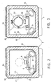
- the container body 2 is made in one sandwich, Figs. 2, 3, having an inner skin 20 in stainless steel, balsa 21 core and skin external 22 of composite material such as composite glass-resin (CVR).
- the thickness of the inner skin 20 stainless steel can be of the order of 2 mm. She performs sealing, mechanical strength, electromagnetic protection and fixing elements including a chassis which will be mentioned in the after.
- the thickness of the balsa core 21 can be close to the 50 mm. It acts as a thermal insulator and gives the sandwich inertia allowing it to resist mechanical stress due to pressure or the thrust of a propellant jet.
- the skin outer 22 may have a thickness of the order of 5 mm. It protects balsa climatically and serves interface for mounting the aforementioned equipment on the outside of the container body 2. All of these thicknesses are given by way of example but are not in no way limiting.
- the inner skin 20 is locally reinforced with another layer of steel highly resistant 23, Fig. 4, layer 23 constituting a splinter guard.
- the container body 2 On its upper side, as can be seen better at Figs. 2 and 3, the container body 2 is provided with a ballistic armor 24 made of metal or composite material, intended to ensure the impact resistance of fragments. Made up of flat elements fixed on profiles, the shield 24 is separated from the outer skin 22 by a enclosed air space, to prevent transmission direct shocks and limit the phenomena of Thermal transfer.
- a ballistic armor 24 made of metal or composite material, intended to ensure the impact resistance of fragments.
- the shield 24 Made up of flat elements fixed on profiles, the shield 24 is separated from the outer skin 22 by a enclosed air space, to prevent transmission direct shocks and limit the phenomena of Thermal transfer.
- the lateral faces of the body. of container 2 are as for them coated with a thermal shielding 25 intended to ensure the resistance to the secondary jet of a propellant.
- the thermal shielding 25 is an ablative coating such as phenolic carbon, phenolic glass or charged silicone, fixed for example by bonding to the outer skin 22. In practice, it may have a thickness of the order of 5 mm.
- Door 3 is made of a sandwich of the same nature as that constituting the container body 2. It is a door with multipoint closure controlled by a removable central handle 35.
- door 3 has a groove peripheral 31 into which a seal is inserted seal 32.
- the seal 32 cooperates with a joint plane 26 mounted at the end of the walls of the body of container 2.
- a second thermal protection seal, not shown, is mounted externally to the climate seal 32.
- the door presents externally a central hollow or bowl region 33 at the bottom of which are installed the closure as well as various components such as a pressure gauge, valve, humidity indicator, shock indicators, etc.
- the handle 35 of the system door closure can be pressed against the bottom of the bowl 33, in the storage position, as shown in solid lines in FIG. 4 and in lines interrupted in FIG. 5.
- the cover 34 is made in a sandwich of the same kind as that constituting the door and the container body.
- panel 4 closing the rear of the container, Fig. 1.
- panel 4 internally has a peripheral groove 41 containing a climate seal 42, while a seal thermal, not shown, is mounted externally by compared to climate seal 42.
- the rear panel 4 is attached to the container body by a system of attachment ensuring its embrittlement in the event of ignition accidental missile propellant.
- this fastening system can consist of a plurality of thermally protected screws.
- the container is equipped to receive a set formed of a missile and its cradle. It is at this effect provided internally with a frame 8 mounted on metal cable shock absorbers 81, themselves mounted on supports 82 fixed to the internal skin in steel 20.
- the chassis 8 essentially comprises two metal rails 80, Figs. 2 and 3, providing support and guiding the cradle of the missile.
- the cradle 9 includes a central beam 90 on which are mounted a collar before 91 and a collar rear 92, Fig. 1, the collars 91 and 92 being more joined together above by a bar 93.
- the material of timing ensuring the interface between the missile and the front collar can provide thermal protection complementary by wrapping the military charge.
- the cradle 9 is provided an anti-thrust device for the ignition case accidental missile propellant: beam 90 of cradle is extended beyond the rear collar 92 to carry a stop plate 94 appearing at the Fig. 1.
- a folding bar 95 ensures the connection upper between the rear collar 92 and the plate 94.
- a system of polarization prohibiting the installation of the cradle 9 in loading position on chassis 8 if the bar link 95 was not previously locked.
- the resumption of the forces generated by the thrust of the engine of the missile is obtained by the mechanical connection of the bars 93 and 95 with the hanging fittings of the missile under aircraft.
Landscapes
- Engineering & Computer Science (AREA)
- General Engineering & Computer Science (AREA)
- Aiming, Guidance, Guns With A Light Source, Armor, Camouflage, And Targets (AREA)
- Pressure Vessels And Lids Thereof (AREA)
- Laminated Bodies (AREA)
- Burglar Alarm Systems (AREA)
- Packages (AREA)
Claims (8)
- Behälter für selbstangetriebene Munition, insbesondere Flugkörper, der eine quaderförmige, dichte Hülle umfasst, innerhalb derer ein Rahmen auf Dämpfungsvorrichtungen montiert ist, um eine Einheit aus einem Flugkörper und seinem Träger aufzunehmen, dadurch gekennzeichnet, dass:die Wände der Hülle aus einer Sandwich-Anordnung mit einer Innenhaut (20) aus Stahl, einem Kern (21) aus Leichtholz wie Balsa und einer Außenhaut (22) aus Verbundmaterial wie einem Glas-Harz-Verbundmaterial bestehen;die Hülle an ihrer oberen Wand eine ballistische Abschirmung (24) aufweist;die Hülle eine versprödete Wand (4) für den Austritt der Gase im Falle einer ungewollten Zündung des Triebwerks des Flugkörpers aufweist;die Hülle innen einen Splitterschutz aufweist, der aus einer Verstärkung (23) der stählernen Innenhaut (20) im Bereich der Ladung des Flugkörpers besteht;der Träger (9) des Flugkörpers mit einer Schubverhinderungsvorrichtung ausgestattet ist.
- Behälter für Flugkörper nach Anspruch 1, dadurch gekennzeichnet, dass er ferner an seinen Seitenwänden eine thermische Abschirmung (25) umfasst.
- Behälter für Flugkörper nach Anspruch 2, dadurch gekennzeichnet, dass die thermische Abschirmung aus einem ablativen Material besteht.
- Behälter für Flugkörper nach einem der. vorstehenden Ansprüche, dadurch gekennzeichnet, dass er vollkommen bedeckt ist mit einer Intumeszenz-Farbe als letztem Anstrich.
- Behälter für Flugkörper nach einem der Ansprüche 1 bis 4, dadurch gekennzeichnet, dass die ballistische Abschirmung (24) aus Elementen besteht, die von der Außenschicht der Hülle durch eine Luftschicht getrennt sind, um die direkte Übertragung von Stößen auf die Hülle zu verhindern und Wärmeübertragungsphänomene zu begrenzen.
- Behälter für Flugkörper nach einem der Ansprüche 1 bis 5, dadurch gekennzeichnet, dass die Hülle vorne durch eine Tür (3) mit Vielstellenschloss verschlossen ist, das durch einen zentralen, abnehmbaren Griff gesteuert wird.
- Behälter für Flugkörper nach Anspruch 6, dadurch gekennzeichnet, dass die Tür (3) außen einen hohlen Mittelbereich (33) aufweist, in dessen Boden das Schließsystem sowie diverse Einrichtungen wie Manometer, Ventil, Feuchtigkeitsanzeiger, Stoßanzeiger, etc. eingebaut sind, wobei der Schutz dieser Einrichtungen durch einen Deckel (34) gewährleistet ist, der diesen hohlen Mittelbereich (33) verschließt.
- Behälter für Flugkörper nach einem der Ansprüche 1 bis 7, dadurch gekennzeichnet, dass die versprödete Wand der Hülle eine Platte (4) ist,-die den hinteren, zur Tür (3) entgegengesetzten Teil verschließt.
Applications Claiming Priority (2)
| Application Number | Priority Date | Filing Date | Title |
|---|---|---|---|
| FR9503522 | 1995-03-20 | ||
| FR9503522A FR2732106B1 (fr) | 1995-03-20 | 1995-03-20 | Conteneur securise pour munition autopropulsee notamment pour missile |
Publications (3)
| Publication Number | Publication Date |
|---|---|
| EP0733876A1 EP0733876A1 (de) | 1996-09-25 |
| EP0733876B1 true EP0733876B1 (de) | 2002-08-14 |
| EP0733876B8 EP0733876B8 (de) | 2003-01-02 |
Family
ID=9477420
Family Applications (1)
| Application Number | Title | Priority Date | Filing Date |
|---|---|---|---|
| EP96460013A Expired - Lifetime EP0733876B8 (de) | 1995-03-20 | 1996-03-19 | Sicherheitsbehälter für selbstangetriebene Flugkörper |
Country Status (4)
| Country | Link |
|---|---|
| EP (1) | EP0733876B8 (de) |
| AT (1) | ATE222348T1 (de) |
| DE (1) | DE69622901T2 (de) |
| FR (1) | FR2732106B1 (de) |
Families Citing this family (5)
| Publication number | Priority date | Publication date | Assignee | Title |
|---|---|---|---|---|
| NL1009979C2 (nl) * | 1998-09-01 | 2000-03-02 | Fokker Special Products | Lanceerbuis uit composietmateriaal. |
| KR102222030B1 (ko) * | 2019-09-19 | 2021-03-02 | 주식회사 한화 | 이동식 유도탄 검사 장치 |
| CN110921108B (zh) * | 2019-12-25 | 2024-10-11 | 常州中航泰克船舶装备有限公司 | 一种长圆柱或长条类物品专用贮运箱 |
| CN111595199B (zh) * | 2020-05-14 | 2022-12-23 | 湖北三江航天万峰科技发展有限公司 | 一种发射箱加热控制装置 |
| CN116697833B (zh) * | 2023-07-28 | 2023-12-29 | 北京爱思达航天科技有限公司 | 一种复合材料包装箱及其制备方法 |
Family Cites Families (7)
| Publication number | Priority date | Publication date | Assignee | Title |
|---|---|---|---|---|
| US3368452A (en) * | 1965-04-19 | 1968-02-13 | Martin Marietta Corp | Shock isolation system |
| US3823903A (en) * | 1972-03-03 | 1974-07-16 | Menasco Mfg Co | Dual length pendulum shock absorbing system |
| US4055247A (en) * | 1976-10-22 | 1977-10-25 | The United States Of America As Represented By The United States Energy Research And Development Administration | Explosion containment device |
| DE3711059C1 (de) * | 1987-04-02 | 1988-10-13 | Krupp Mak Maschb Gmbh | Ausbildung von Ablauf-,Ausstossrohren oder Behaeltnissen in U-Booten |
| FR2619088B1 (fr) * | 1987-08-04 | 1989-11-24 | Mediterranee Const Ind | Systeme de suspension d'elements cylindriques dans des conteneurs notamment systemes de suspension de missiles pour sous-marin lance-missiles |
| FR2656085B1 (fr) * | 1987-10-13 | 1994-03-25 | Thomson Brandt Armements | Munition explosive protegee contre l'elevation de temperature. |
| DE4129384A1 (de) * | 1991-09-04 | 1993-03-11 | Deutsche Aerospace | Transportbehaelter |
-
1995
- 1995-03-20 FR FR9503522A patent/FR2732106B1/fr not_active Expired - Lifetime
-
1996
- 1996-03-19 EP EP96460013A patent/EP0733876B8/de not_active Expired - Lifetime
- 1996-03-19 DE DE69622901T patent/DE69622901T2/de not_active Expired - Lifetime
- 1996-03-19 AT AT96460013T patent/ATE222348T1/de not_active IP Right Cessation
Also Published As
| Publication number | Publication date |
|---|---|
| DE69622901T2 (de) | 2003-04-10 |
| DE69622901D1 (de) | 2002-09-19 |
| FR2732106A1 (fr) | 1996-09-27 |
| ATE222348T1 (de) | 2002-08-15 |
| EP0733876B8 (de) | 2003-01-02 |
| EP0733876A1 (de) | 1996-09-25 |
| FR2732106B1 (fr) | 1997-05-30 |
Similar Documents
| Publication | Publication Date | Title |
|---|---|---|
| US7908959B2 (en) | System and method for protecting vehicle occupants | |
| EP0005111B1 (de) | In Gewicht vermindertes Panzerfahrzeug | |
| US20050188825A1 (en) | Explosive effect mitigated containers | |
| FR2741708A1 (fr) | Ensemble de blindage | |
| US8783157B2 (en) | System and method for protecting vehicle occupants | |
| US8418597B2 (en) | System and method for protecting vehicle occupants | |
| CA2426351C (fr) | Systeme d'obturation pour un orifice d'un conduit, en particulier pour un orifice d'une voie d'introduction d'air dans la chambre de combustion d'un statoreacteur | |
| EP0733876A1 (de) | Sicherheitsbehälter für selbstangetriebene Flugkörper | |
| US7422102B1 (en) | Container for ammunition | |
| FR2563901A1 (fr) | Panneau d'ecoutille pour vehicule de combat | |
| US4432269A (en) | Weapon system | |
| US5022307A (en) | Light weight attenuator of blast and shock from detonating munitions | |
| US5611424A (en) | Container fuse for enhanced survivability | |
| FR2692973A1 (fr) | Elément d'obturation pour tube de lancement de munition et tube de lancement le comportant. | |
| US4885994A (en) | Armor penetration resistance enhancement | |
| RU2175457C2 (ru) | Контейнер для перевозки опасных и ценных грузов | |
| EP0988239B1 (de) | Kastenförmiger behälter zum transport von zerbrechlichen und/oder wertvollen gegenständen | |
| FR2723192A1 (fr) | Element de blindage pour vehicules | |
| KR20170038204A (ko) | 추진장약 포장용기 | |
| EP0633447A1 (de) | Tarnungsvorrichtung | |
| EP1637830B1 (de) | Vorrichtung zur Abkapselung einer Vielzahl von explosiven Gegenständen | |
| GB2108055A (en) | De-icing of doors | |
| EP0481851B1 (de) | Schliess- und Schutzvorrichtung für ein Gasauslasssystem eines senkrechten Abschussmoduls | |
| FR2863350A1 (fr) | Blindage de protection d'un milieu interieur et vehicule ainsi blinde | |
| FR2853053A1 (fr) | Blindage actif |
Legal Events
| Date | Code | Title | Description |
|---|---|---|---|
| PUAI | Public reference made under article 153(3) epc to a published international application that has entered the european phase |
Free format text: ORIGINAL CODE: 0009012 |
|
| AK | Designated contracting states |
Kind code of ref document: A1 Designated state(s): AT BE CH DE DK ES FI GB IT LI NL SE |
|
| 17P | Request for examination filed |
Effective date: 19970124 |
|
| GRAG | Despatch of communication of intention to grant |
Free format text: ORIGINAL CODE: EPIDOS AGRA |
|
| 17Q | First examination report despatched |
Effective date: 20010726 |
|
| RBV | Designated contracting states (corrected) |
Designated state(s): AT BE CH DE DK ES FI GB IT LI NL SE |
|
| GRAG | Despatch of communication of intention to grant |
Free format text: ORIGINAL CODE: EPIDOS AGRA |
|
| GRAH | Despatch of communication of intention to grant a patent |
Free format text: ORIGINAL CODE: EPIDOS IGRA |
|
| GRAH | Despatch of communication of intention to grant a patent |
Free format text: ORIGINAL CODE: EPIDOS IGRA |
|
| GRAA | (expected) grant |
Free format text: ORIGINAL CODE: 0009210 |
|
| AK | Designated contracting states |
Kind code of ref document: B1 Designated state(s): AT BE CH DE DK ES FI GB IT LI NL SE |
|
| PG25 | Lapsed in a contracting state [announced via postgrant information from national office to epo] |
Ref country code: NL Free format text: LAPSE BECAUSE OF FAILURE TO SUBMIT A TRANSLATION OF THE DESCRIPTION OR TO PAY THE FEE WITHIN THE PRESCRIBED TIME-LIMIT Effective date: 20020814 Ref country code: FI Free format text: LAPSE BECAUSE OF FAILURE TO SUBMIT A TRANSLATION OF THE DESCRIPTION OR TO PAY THE FEE WITHIN THE PRESCRIBED TIME-LIMIT Effective date: 20020814 Ref country code: AT Free format text: LAPSE BECAUSE OF FAILURE TO SUBMIT A TRANSLATION OF THE DESCRIPTION OR TO PAY THE FEE WITHIN THE PRESCRIBED TIME-LIMIT Effective date: 20020814 |
|
| REF | Corresponds to: |
Ref document number: 222348 Country of ref document: AT Date of ref document: 20020815 Kind code of ref document: T |
|
| REG | Reference to a national code |
Ref country code: GB Ref legal event code: FG4D Free format text: NOT ENGLISH |
|
| REG | Reference to a national code |
Ref country code: CH Ref legal event code: EP |
|
| GBT | Gb: translation of ep patent filed (gb section 77(6)(a)/1977) |
Effective date: 20020814 |
|
| REF | Corresponds to: |
Ref document number: 69622901 Country of ref document: DE Date of ref document: 20020919 |
|
| RAP2 | Party data changed (patent owner data changed or rights of a patent transferred) |
Owner name: DAHER LHOTELLIER CSI Owner name: ETAT FRANCAIS REPRESENTE PAR LE DELEGUE GENERAL PO |
|
| REG | Reference to a national code |
Ref country code: GB Ref legal event code: 732E |
|
| PG25 | Lapsed in a contracting state [announced via postgrant information from national office to epo] |
Ref country code: SE Free format text: LAPSE BECAUSE OF FAILURE TO SUBMIT A TRANSLATION OF THE DESCRIPTION OR TO PAY THE FEE WITHIN THE PRESCRIBED TIME-LIMIT Effective date: 20021114 Ref country code: DK Free format text: LAPSE BECAUSE OF FAILURE TO SUBMIT A TRANSLATION OF THE DESCRIPTION OR TO PAY THE FEE WITHIN THE PRESCRIBED TIME-LIMIT Effective date: 20021114 |
|
| NLT2 | Nl: modifications (of names), taken from the european patent patent bulletin |
Owner name: ETAT FRANCAIS EN DAHER LHOTELLIER CSI |
|
| NLV1 | Nl: lapsed or annulled due to failure to fulfill the requirements of art. 29p and 29m of the patents act | ||
| PG25 | Lapsed in a contracting state [announced via postgrant information from national office to epo] |
Ref country code: ES Free format text: LAPSE BECAUSE OF FAILURE TO SUBMIT A TRANSLATION OF THE DESCRIPTION OR TO PAY THE FEE WITHIN THE PRESCRIBED TIME-LIMIT Effective date: 20030228 |
|
| PG25 | Lapsed in a contracting state [announced via postgrant information from national office to epo] |
Ref country code: LI Free format text: LAPSE BECAUSE OF NON-PAYMENT OF DUE FEES Effective date: 20030331 Ref country code: CH Free format text: LAPSE BECAUSE OF NON-PAYMENT OF DUE FEES Effective date: 20030331 Ref country code: BE Free format text: LAPSE BECAUSE OF NON-PAYMENT OF DUE FEES Effective date: 20030331 |
|
| PLBE | No opposition filed within time limit |
Free format text: ORIGINAL CODE: 0009261 |
|
| STAA | Information on the status of an ep patent application or granted ep patent |
Free format text: STATUS: NO OPPOSITION FILED WITHIN TIME LIMIT |
|
| 26N | No opposition filed |
Effective date: 20030515 |
|
| BERE | Be: lapsed |
Owner name: S.A. *LHOTELLIER MONTRICHARD Effective date: 20030331 Owner name: ETAT FRANCAIS REPRESENTE PAR LE DELEGUE GENERAL PO Effective date: 20030331 |
|
| REG | Reference to a national code |
Ref country code: CH Ref legal event code: PL |
|
| REG | Reference to a national code |
Ref country code: GB Ref legal event code: 732E |
|
| PGFP | Annual fee paid to national office [announced via postgrant information from national office to epo] |
Ref country code: IT Payment date: 20140318 Year of fee payment: 19 |
|
| PGFP | Annual fee paid to national office [announced via postgrant information from national office to epo] |
Ref country code: GB Payment date: 20140319 Year of fee payment: 19 |
|
| PGFP | Annual fee paid to national office [announced via postgrant information from national office to epo] |
Ref country code: DE Payment date: 20140417 Year of fee payment: 19 |
|
| REG | Reference to a national code |
Ref country code: DE Ref legal event code: R119 Ref document number: 69622901 Country of ref document: DE |
|
| GBPC | Gb: european patent ceased through non-payment of renewal fee |
Effective date: 20150319 |
|
| PG25 | Lapsed in a contracting state [announced via postgrant information from national office to epo] |
Ref country code: IT Free format text: LAPSE BECAUSE OF NON-PAYMENT OF DUE FEES Effective date: 20150319 |
|
| PG25 | Lapsed in a contracting state [announced via postgrant information from national office to epo] |
Ref country code: GB Free format text: LAPSE BECAUSE OF NON-PAYMENT OF DUE FEES Effective date: 20150319 Ref country code: DE Free format text: LAPSE BECAUSE OF NON-PAYMENT OF DUE FEES Effective date: 20151001 |