EP0734951A2 - Vorrichtung und Verfahren zum Vakuumsiegeln von Beuteln - Google Patents
Vorrichtung und Verfahren zum Vakuumsiegeln von Beuteln Download PDFInfo
- Publication number
- EP0734951A2 EP0734951A2 EP96103240A EP96103240A EP0734951A2 EP 0734951 A2 EP0734951 A2 EP 0734951A2 EP 96103240 A EP96103240 A EP 96103240A EP 96103240 A EP96103240 A EP 96103240A EP 0734951 A2 EP0734951 A2 EP 0734951A2
- Authority
- EP
- European Patent Office
- Prior art keywords
- pouch
- snorkel
- guide member
- heat
- sealing
- Prior art date
- Legal status (The legal status is an assumption and is not a legal conclusion. Google has not performed a legal analysis and makes no representation as to the accuracy of the status listed.)
- Granted
Links
- 238000007789 sealing Methods 0.000 title claims abstract description 116
- 238000000034 method Methods 0.000 title claims abstract description 36
- 239000000523 sample Substances 0.000 claims abstract description 62
- 238000010438 heat treatment Methods 0.000 claims description 18
- 238000004806 packaging method and process Methods 0.000 claims description 13
- 238000001816 cooling Methods 0.000 claims description 8
- 229910003460 diamond Inorganic materials 0.000 claims 1
- 239000010432 diamond Substances 0.000 claims 1
- 239000000463 material Substances 0.000 description 12
- 230000008878 coupling Effects 0.000 description 5
- 238000010168 coupling process Methods 0.000 description 5
- 238000005859 coupling reaction Methods 0.000 description 5
- XAGFODPZIPBFFR-UHFFFAOYSA-N aluminium Chemical compound [Al] XAGFODPZIPBFFR-UHFFFAOYSA-N 0.000 description 3
- 229910052782 aluminium Inorganic materials 0.000 description 3
- 230000001419 dependent effect Effects 0.000 description 3
- 239000000047 product Substances 0.000 description 3
- 239000012858 resilient material Substances 0.000 description 3
- PXHVJJICTQNCMI-UHFFFAOYSA-N Nickel Chemical compound [Ni] PXHVJJICTQNCMI-UHFFFAOYSA-N 0.000 description 2
- 230000033228 biological regulation Effects 0.000 description 2
- 229920001971 elastomer Polymers 0.000 description 2
- 229920001821 foam rubber Polymers 0.000 description 2
- 230000001737 promoting effect Effects 0.000 description 2
- VYZAMTAEIAYCRO-UHFFFAOYSA-N Chromium Chemical compound [Cr] VYZAMTAEIAYCRO-UHFFFAOYSA-N 0.000 description 1
- 229920004943 Delrin® Polymers 0.000 description 1
- 229910000831 Steel Inorganic materials 0.000 description 1
- 238000003491 array Methods 0.000 description 1
- 239000006227 byproduct Substances 0.000 description 1
- 229910052804 chromium Inorganic materials 0.000 description 1
- 239000011651 chromium Substances 0.000 description 1
- 230000001934 delay Effects 0.000 description 1
- 230000017525 heat dissipation Effects 0.000 description 1
- 239000011810 insulating material Substances 0.000 description 1
- 229910001120 nichrome Inorganic materials 0.000 description 1
- 229910052759 nickel Inorganic materials 0.000 description 1
- 230000002093 peripheral effect Effects 0.000 description 1
- 229920002635 polyurethane Polymers 0.000 description 1
- 239000004814 polyurethane Substances 0.000 description 1
- 238000002360 preparation method Methods 0.000 description 1
- 238000003825 pressing Methods 0.000 description 1
- 238000004886 process control Methods 0.000 description 1
- 230000035945 sensitivity Effects 0.000 description 1
- 239000007787 solid Substances 0.000 description 1
- 229910001220 stainless steel Inorganic materials 0.000 description 1
- 239000010935 stainless steel Substances 0.000 description 1
- 239000010959 steel Substances 0.000 description 1
- XLYOFNOQVPJJNP-UHFFFAOYSA-N water Substances O XLYOFNOQVPJJNP-UHFFFAOYSA-N 0.000 description 1
Images


Classifications
-
- B—PERFORMING OPERATIONS; TRANSPORTING
- B65—CONVEYING; PACKING; STORING; HANDLING THIN OR FILAMENTARY MATERIAL
- B65B—MACHINES, APPARATUS OR DEVICES FOR, OR METHODS OF, PACKAGING ARTICLES OR MATERIALS; UNPACKING
- B65B31/00—Packaging articles or materials under special atmospheric or gaseous conditions; Adding propellants to aerosol containers
- B65B31/04—Evacuating, pressurising or gasifying filled containers or wrappers by means of nozzles through which air or other gas, e.g. an inert gas, is withdrawn or supplied
- B65B31/06—Evacuating, pressurising or gasifying filled containers or wrappers by means of nozzles through which air or other gas, e.g. an inert gas, is withdrawn or supplied the nozzle being arranged for insertion into, and withdrawal from, the mouth of a filled container and operating in conjunction with means for sealing the container mouth
Definitions
- the invention relates to an apparatus for packaging objects. More particularly, the invention relates to an apparatus and method for vacuum sealing objects in various size pouches.
- a variety of apparatus and methods are known for wrapping or pouching objects in containers, particularly objects made from flexible materials. Such known apparatus and methods are limited in their abilities to adjust readily for changes in the size of the objects, the size or format of the container, or both. Many such known apparatus and methods are also limited in their abilities to wrap or pouch objects which require more gentle handling due to their ease of damage or their unstable structure. For example, stacks of slippery sheets of x-ray film or photographic paper must be handled carefully due to the sensitivity of the film to scratches, pressure marks, and the like. In addition, stacks of sheets of such objects having slippery surface properties are easily shifted out of their desired right-rectangular stack configuration, thereby producing an irregularly shaped, skewed stack which is difficult to handle and package.
- the objects are vacuum sealed in the pouch so that the objects will not slide from their stack configuration.
- the amount of vacuum affects the packaging quality, as does the heat seal required to maintain the vacuum within the sealed pouch.
- the vacuum and seal must be sufficient to secure the objects within the pouch, yet allow a user to tear the pouch open to access the objects.
- FIG 1 shows a pouch and an object of some typical types.
- Pouch 10 can be formed from a pair of preferably congruent opposed side walls 12,14 joined together by a peripheral seal 16, such as a continuous heat seal, but unjoined on one side, thereby forming an opening or mouth 18.
- the joined sides may include flaps, rip strips, or other features desired for a particular application.
- a typical object to be packaged would be a single object or an essentially right rectangular stack 20 of sheet material.
- the top and bottom sheet of stack 20 may be covered by dunnage cards 22,24 to protect the object during handling.
- pouch 10 can be evacuated of air which causes side walls 12,14 to conform generally to the shape of the object.
- Mouth 18 can be closed by a seal 26, to produce a packaged object of the general configuration shown in FIG 2.
- FIG 3 discloses pouch 10 positioned for evacuating and sealing.
- a pouch evacuation apparatus 28 is provided which comprises a pneumatic actuator 30.
- the actuator rod of actuator 30 extends toward the rear of the apparatus and fixedly supports a transverse support block 32 for a pair of evacuator probes or tubes 34, only one of which appears in FIG 3.
- Probes 34 are positioned essentially on the centerline of the open mouth of pouch 10, and are connected to a suitable vacuum source.
- Above and below probes 34 are mounted upper and lower pouch closing and sealing jaws 36 which comprise upper and lower pairs of pneumatic actuators 38 having actuator rods 40 which support transversely extending mounting bars 42.
- Attached to bars 42 are pairs of aligned, oppositely facing and transversely extending heat sealing bars or jaws 44.
- Actuator rods 46 of upper and lower pairs of pneumatic actuators 48 support aligned, oppositely facing and transversely extending pouch closing bars or clamping jaws 50, each having a layer 52 of foam rubber or similar resilient material on its surface facing probes 34.
- Actuator 30 extends probes 34 through the mouth of pouch 10 into fairly close proximity to the enclosed object.
- Actuators 48 are then actuated to extend clamping jaws 50 into contact with the side walls of pouch 10, thus compressing layers 52 to provide a mechanical seal between the side walls and around the extended probes 34.
- Vacuum is then applied to probes 34 for a time sufficient to evacuate the pouch, after which probes 34 are withdrawn behind sealing edges 44, but with the vacuum still being drawn. Actuators 38 are then actuated to press sealing jaws 44 into contact with pouch 10 to form seal 26 and complete the package. Vacuum is then stopped and actuators 38, 48 are deactuated to release the package.
- An object of the invention is to provide a packaging apparatus whose vacuum levels can be precisely controlled, provides consistent vacuum levels in the packaged object, and achieves high levels of vacuum during the vacuum sealing process.
- a further object of the invention is to provide a apparatus which forms a mechanical seal during the evacuation process.
- Another object of the invention is to provide an apparatus which does not clog during the vacuum sealing process.
- Yet another object of the invention is to provide a method for selectively controlling the heat sealing process.
- an apparatus for packaging an object in a pouch, the pouch having an opposed pair of side walls joined to form an open mouth.
- a frame with a support surface supports the pouch and a snorkel assembly.
- the snorkel assembly includes a snorkel guide member telescopically surrounding a probe.
- the probe moves axially relative to the snorkel guide member and has an end adapted to be inserted into the pouch through the open mouth.
- Means are provided to move probe between an extended within the pouch and a withdrawn position.
- the probe includes an axial channel through which air can flow. When vacuum is applied to the axial channel, air can be removed from the pouch.
- a clamp assembly is transversely mounted relative to the snorkel assembly, and includes a pair of clamping jaws which move relative to each other between an open and closed position.
- a seal assembly is transversely mounted relative to the snorkel assembly and is positioned between the object in the pouch and the clamp assembly.
- the seal assembly has a pair of sealing jaws which move between an open and closed position. In the closed position, the sealing jaws engage the pouch therebetween to form a seal in the open mouth.
- the apparatus comprises a frame with a support surface supporting the pouch and a snorkel assembly.
- the snorkel assembly includes a snorkel guide member telescopically surrounding a probe.
- the probe moves axially relative to the snorkel guide member and has an end adapted to be inserted into the pouch through the open mouth.
- Means are provided to move probe between an extended within the pouch and a withdrawn position.
- the probe includes an axial channel through which air can flow. When vacuum is applied to the axial channel, air can be removed from the pouch.
- a clamp assembly is transversely mounted relative to the snorkel assembly, and includes a pair of clamping jaws which move relative to each other between an open and closed position.
- the clamping jaws each include a clamping notch, where the clamping notches define an aperture geometrically similar to an external configuration of the snorkel guide member.
- the clamping notches engage and clamp the pouch around the snorkel guide member when the clamping jaws are in their closed position.
- a seal assembly is transversely mounted relative to the snorkel assembly and is positioned between the object in the pouch and the clamp assembly.
- the seal assembly has a pair of sealing jaws which move between an open and closed position. In the closed position, the sealing jaws engage the pouch therebetween to form a seal in the open mouth.
- a method for packaging an object in a pouch comprising the steps of: providing a snorkel assembly having a snorkel guide member telescopically surrounding a probe, the probe including an end and an axial channel through which air can flow, the probe being axially movable relative to the snorkel guide member; extending the end of the probe from the snorkel guide member; inserting the end of the probe into the pouch through the open mouth; clamping the pouch around the snorkel guide member; applying a vacuum to the axial channel to remove air from the pouch; withdrawing the end of the probe into the snorkel guide member; engaging the open mouth of the pouch between a first and second sealing jaw; disengaging the vacuum to the axial channel; applying heat to the first and second sealing jaws to heat seal the open mouth of the pouch; disengaging the first and second sealing jaws; and unclamping the pouch from around the snorkel guide member.
- a method for selectively applying heat to a sealing jaw to heat seal an open mouth of a pouch includes the steps of: selecting a total heat cycle time during which heat can be applied by the sealing jaw to the pouch; selecting a cycle time increment which is less than the total heat cycle time; selecting a minimum time increment during which heat can be applied to the sealing jaw, the minimum time increment being less than the cycle time increment; selecting a maximum time increment during which heat can be applied to the sealing jaw, the maximum time increment being greater than or equal to the minimum time increment, and being less than the cycle time increment; selecting a desired temperature at which to heat the sealing jaw to form the heat seal; and selecting a baseline temperature by which to regulate the application of heat to the sealing jaw, the baseline temperature being less than the desired temperature.
- a heating-on time is calculated by sensing an actual temperature of the sealing jaw, determining a difference between the desired temperature and the actual temperature, setting the heating-on time to the maximum time increment if the difference is greater than or equal to the baseline temperature, setting the heating-on time to a value less than the maximum time increment and greater than zero if the difference is less than the baseline temperature, and greater than zero, and setting the heating-on time to zero if the difference is less than or equal to zero.
- the sealing jaw is heated for the heating-on time, and then the sealing jaw is cooled by turned off the heat for the remainder of the cycle time increment. The steps of calculating, heating, and cooling are repeated for each cycle time increment until the total heat cycle time is reached.
- an apparatus for selectively applying heat to a sealing jaw to heat seal an open mouth of a pouch includes means for selecting a cycle time increment during which heat can be applied to the sealing jaw; means for selecting a minimum time increment during which heat can be applied to the sealing jaw, the minimum time increment being less than the cycle time increment; means for selecting a maximum time increment during which heat can be applied to the sealing jaw, the maximum time increment being greater than or equal to the minimum time increment, and being less than the cycle time increment; means for selecting a desired temperature at which to heat the sealing jaw to form the heat seal; and means for selecting a baseline temperature by which to regulate the application of heat to the sealing jaw, the baseline temperature being less than the desired temperature.
- the apparatus further includes means for sensing an actual temperature of the sealing jaw; means for calculating a heating-on time for each cycle time increment based on a difference between the desired temperature and the actual temperature; means for applying heat to the sealing jaw for the heating-on time; and means for turning off heat to the sealing jaw for the remainder of the cycle time increment.
- An advantage of the apparatus of the invention is that it is flexible enough to handle changes in object size, the size or format of the container, or both; allows control of the vacuum during the sealing process; provides consistent vacuum levels in the packaged objects; provides a mechanical seal during evacuation of the pouch; generates a heat seal; achieves a high level of vacuum; provides a non-clogging evacuation system; allows for system set-up by product; and allows for benchmarking (for example, quality checks) of the system.
- FIG. 1 shows a perspective view of an object and pouch of a type known in the art, but useful in the apparatus of the invention.
- FIG. 2 shows a perspective view of a completed package of a type closed and sealed by the apparatus of the invention.
- FIG. 3 shows a section view of a prior art apparatus for closing and sealing a pouch of the type illustrated in FIG. 1 and FIG. 2.
- FIG. 4 shows a top view of the apparatus of the invention.
- FIG. 5 shows a side view of the snorkel assembly of the invention.
- FIG. 6 shows an enlarged end view of the snorkel assembly, as seen from the right in FIG. 5.
- FIG. 7(a) shows a first embodiment of a section view through the apparatus of the invention, taken along line 7-7 of FIG. 4.
- FIG. 7(b) shows a second embodiment of a section view through the apparatus of the invention, taken along line 7-7 of FIG. 4.
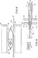
- FIG. 8 shows a section view through the apparatus of the invention, taken along line 8-8 of FIG. 4.
- FIG. 9 shows a section view through the apparatus of the invention, taken along line 9-9 of FIG. 4.
- FIG. 10 shows the embodiment of the clamping jaws of FIG 7(b) in their closed position.
- FIG. 11 shows a side elevation of the snorkel assembly, and the mounting fixture.
- FIG. 12 shows a flowchart of steps of a method of the invention.
- FIG. 13 shows a flowchart of the steps of heating and cooling the sealing jaws identified in FIG. 12.
- FIG. 14 shows a continuation of the flowchart of FIG. 13.
- FIG. 15 shows a plot of time versus temperature profile for heating the sealing jaws of the invention.
- FIG. 16 shows a plot of time versus heating profile for heating the sealing jaws of the invention, corresponding with FIG. 15.
- pouches for use in the invention may be made from any suitable material but preferably the material is gas impervious and can be heat sealed. Such pouches can be stacked flat and are readily picked up and moved by conventional means such as suction cup arrays.
- Stack 20 may be, for example, x-ray film sheets or photographic paper.
- Mouth 18 may be held open by conventional means, such as a suction cup array, and the object can be positioned inside pouch 10 through mouth 18.
- FIG 4 shows the apparatus of the invention which comprises a frame 54 having a support surface 56, a seal assembly 58 including upper and lower sealing jaws 44, a clamp assembly 60 including upper and lower clamping jaws 50, pouch evacuation assembly 28 including a snorkel assembly 62,.a mounting fixture 64 for mounting snorkel assembly 62 to frame 54, a snorkel extension means 65, and a vacuum source in association with snorkel assembly 62.
- a mounting fixture 64 for mounting snorkel assembly 62 to frame 54
- a snorkel extension means 65 and a vacuum source in association with snorkel assembly 62.
- Support surface 56 supports pouch 10.
- a source or hopper (not shown) of pouches may be attached or associated with support surface 56.
- Pouches 10 can be removed from the source and oriented on support surface 56 by any suitable means, such as manually or with a programmable robot.
- Support surface 56 may include a guide fixture (not shown) to orient pouch 10 for sealing.
- Support surface 56 may further include removal means (not shown) for removing filled, evacuated, and sealed packages.
- snorkel assembly 62 includes a snorkel support member 66, an elongated snorkel guide member 68 having an end 69, and an elongated, generally tubular probe 70 having an end 72.
- Snorkel guide member 68 telescopically surrounds probe 70. That is, a first channel 74 extends axially through snorkel guide member 68 and snorkel support member 66.
- Probe 70 is configured to be closely fit (that is, minimal clearance) within first channel 74, thereby minimizing leakage between probe 70 and first channel 74.
- Probe 70 is movable axially within channel 74 so that probe end 72 can be extended outward of snorkel guide member end 69 by snorkel extension means 65, for example, pneumatic actuator 30.
- probe 70 is a telescoping inner-snorkel which can be extended or retracted (that is, withdrawn) from snorkel guide member 68.
- a second channel 76 extends axially through probe 70 through which air can flow, allowing for the evacuation of pouch 10.
- snorkel support member 66 telescopically surrounds snorkel guide member 68. That is, snorkel guide member would be movable axially within snorkel support member 66, for example, by pneumatic actuator 30, and probe 70 would be movable axially within snorkel guide member 68.
- seal assembly 58 is positioned transversely to support surface 56, so as to be positioned between stack 20 and clamping assembly 60.
- Sealing jaws 44 each having a sealing edge 82, move relative to each other between an open position and a closed position. In the open position, sealing edges 82 are spaced apart from each other to allow pouch 10 and probe 70 to be positioned therebetween. In the closed position, sealing edges 82 are pressed into contact with pouch 10 to provide a mechanical seal between sealing edges 82 and pouch 10, such that heat can be applied to heat seal the unjoined end of pouch 10.
- Conventional actuation means such as pneumatic actuators 38, can be used to move sealing jaws 44 between their open and closed positions.
- the closed position can be accomplished by moving one sealing jaw while holding the other sealing jaw stationary or by moving both sealing jaws 44.
- Sealing jaws 44 can be of any size, however, the length of sealing edges 82 must be at least the length of the unjoined side of pouch 10 in order to seal the length.
- sealing jaws 44 can comprise a heat conducting element (for example, NICHROME, trademark of the Driver-Harris Company, including nickel and chromium), an insulating material, a support material (for example, aluminum), a heat sensor (for example, thermocouple(s) 86), and a compliant member (for example, rubber) providing compliance to form a seal.
- clamp assembly 60 is positioned transversely to support surface 56 such that seal assembly 58 is positioned between stack 20 and clamp assembly 60.
- clamp assembly 60 comprises two clamping jaws 50, each with a clamping edge 90.
- Clamping jaws 50 move relative to each other between an open position and a closed position. In the open position, clamping edges 90 are spaced apart from each other such that snorkel guide member 68 and pouch 10 can be positioned therebetween. In the closed position, clamping edges 90 are pressed together to engage and clamp pouch 10 around snorkel guide member 68, to provide a mechanical seal between clamping edges 90, snorkel guide member 68, and pouch 10.
- Conventional actuation means such as pneumatic actuators 38, can be used to move clamping jaws 50 between their open and closed positions.
- the closed position can be accomplished by moving one clamping jaw while holding the other clamping jaw stationary or by moving both clamping jaws 50.
- Clamping jaws 50 can be of any size, however, the length of clamping edges 90 must be at least the length of the unjoined side of pouch 10 in order to clamp its length.
- Clamping jaws 50 engage and clamp snorkel guide member 68 around pouch 10 to form a mechanical seal between clamping edges 50, clamping edges 90 and pouch 10, between pouch 10 and snorkel guide member 68, and between sides 12,14 of pouch 10.
- Clamping jaws 50 can have various configurations to form such a mechanical seal, thereby promoting precision evacuation.
- clamping edges 90 each include a linear edge.
- clamping edges 90 each include a clamping notch 94 defining an aperture 98 which can, for example, be configured geometrically similar to the external configuration of snorkel guide member 68.
- Snorkel guide member 68 would then be positioned within aperture 98 (and accordingly, clamping notches 94) when clamping jaws 50 are in their closed position.
- FIG 10 illustrates clamping jaws 50 in their closed position, so that clamping notches 94 engage snorkel guide member 68 and pouch 10.
- a high clamping force ensures a mechanical hermetic seal, thereby promoting precise control during the vacuum process.
- Snorkel guide member 68 can be of various external configurations (that is, shapes), for example, semi-circular, oval, oblong, or diamond-shaped.
- FIG 6 illustrates one embodiment of the diamond-shaped configuration of snorkel guide member 68 wherein the diamond-shaped cross-section is defined by internal angles of 60 degrees and 120 degrees.
- probe 70, and channels 74,76 can have various configurations, though a circular cross-section is illustrated.
- Snorkel guide member 68 and probe 70 can be made of conventional materials, such as DELRIN, aluminum, or stainless steel.
- Clamping jaws 50 can be made of any conventional material, such as aluminum or steel.
- Clamping edges 90 can likewise be made of the same material as clamping jaws 50, or each clamping edge can have layer 52 of foam rubber or similar resilient material.
- only one edge of clamping edges 90 can include layer 52, for example, of 30-70 durometer polyurethane (preferably 40 durometer), as illustrated in FIG 7(b), while the other edge is of a harder material.
- a suitable clamping force is in the range of 100-200 psi.
- Mounting fixture 64 comprises a flexible coupling 100, such as a rubber coupling, mounting bracket 102 for attachment to frame 54, and a probe holder 104. While mounting fixture 64 need not include flexible coupling 100, some flexibility in the mounting is preferable to provide compliance in the system, for example, when engaging and clamping pouch 10 around snorkel guide member 68 between clamping notches 94; flexible coupling 100 provides such flexibility.
- Other mounting means for mounting snorkel assembly 62 will be known to those skilled in the art.
- a tube 106 Attached to snorkel assembly 62 is a tube 106, or other means though which air may flow.
- a vacuum source or generator 108 in association with tube 106 provides vacuum to evacuate air from pouch 10.
- a vacuum sensor 110 senses the level of vacuum in tube 106, and accordingly, pouch 10.
- a Programmable Logic Controller (PLC) 112 directs the level of vacuum sensed by vacuum sensor 110 to vacuum generator 108 by means of a transducer or converter 113, which converts the voltage signal to a vacuum level.
- PLC Programmable Logic Controller
- Snorkel assembly 62 is preferably positioned parallel to support surface 56 and essentially on the centerline of the open mouth of pouch 10.
- Probe 70 can be either extended or retracted from snorkel guide member 68.
- snorkel guide member 68 is movable relative to snorkel support member 66, snorkel guide member 68 can be extended or retracted from snorkel support member 66.
- probe 70 is in its extended position (114).
- Pouch 10 is positioned on support surface 56 with mouth 18 facing snorkel assembly 62, and overhanging frame 54(116).
- Snorkel guide member 68 and probe 70 are inserted into mouth 18 of pouch 10. While the placement of pouch 10 is dependent on the application, pouch 10 is placed such that it will be engaged by both seal assembly 58 and clamp assembly 60.
- the placement of snorkel assembly 62 relative to pouch 10 is dependent on the application. That is, the placement of snorkel assembly 62 depends on the size of pouch 10 and the placement of stack 20 within pouch 10. For example, as shown in FIG 4, stack 20 is positioned on the right side of pouch 10. Accordingly, snorkel assembly 62 is positioned to the left side of pouch 10. However, snorkel assembly could have been positioned above stack 20.
- Snorkel assembly 62 is inserted inside pouch 10 such that clamping notches 94 will close over snorkel guide member 68 and pouch 10, and not close over snorkel support member 66 or probe 70.
- Sealing edges 82 should not intersect snorkel support member 66 or snorkel guide member 68 when in their closed position. Nor should sealing edges 82 intersect probe 70 in its extended or retracted position when in sealing edges 82 are in their closed position. Probe 70 should extend within a few millimeters of stack 20. Preferably, the distance from probe end 72 to stack 20 is approximately equal to one-half the thickness of stack 20 (that is the object being packaged). Such a positioning ensures that probe 70 does not clog (that is, not blocked by stack 20 or pouch 10; the pouch does not collapse around probe 70) during evacuation.
- the element parameters are initialized (118). These element parameters can be initialized manually, or a central instrument, such as PLC 112, can provide an on-line total process control system. Such an instrument could include a user interacting with a menu 119 (as illustrated in FIG 11) to select stored, pre-set parameters for particular object/pouch configurations, thereby allowing a user to recall settings with one selection. This allows for instantaneous set-up of established variables and repeatable results independent of human error, and allows a means to diagnose the process and establish product quality benchmarks.
- Clamp jaws 50 are oriented to their closed position such that clamping notches 94 engage and clamp pouch 10 around snorkel guide member 68 (120).
- the vacuum is initiated (122) and maintained (124) until a determination is made that the desired vacuum level is reached (126).
- Probe 70 is retracted while still maintaining vacuum (128).
- Sealing jaws 44 are oriented to their closed position, thereby engaging and pressing pouch 10 (130).
- the vacuum can be turned off (132). (Alternatively, vacuum can be maintained until the heat seal is formed.)
- With sealing jaws 44 closed heat is applied to sealing jaws 44 to form a heat seal of pouch 10 (134). When the desired seal is obtained, the heat is stopped, and sealing jaws 44 cool (or chill) while still in their closed position (136).
- Sealing jaws 44 are then oriented to their open position (138), and clamping jaws 50 open to release pouch 10 (140). The sealed pouch can then be removed by conventional means (142). Probe 70 is then preferably extended in preparation of another packaging operation (144). If another packaging operation is to occur (146), the steps are repeated from step 116, although, depending on the application the parameters (step 118) may not need to be reinitialized. If another packaging operation will not occur, the process is stopped (148).
- the parameters to be initialized (118), for example, which could be set using menu 119, include:
- menu 119 Other parameters typically set for each apparatus (and therefore, need not be set for each individual packaging operation), for example by menu 119, include:
- PLC 112 directs the level of vacuum sensed by vacuum sensor 110 to vacuum generator 108 by means of converter 113.
- the signal from PLC 112 is between 0-10 volts DC, and is converted to 0-30 inches Hg by converter 113.
- the signal from vacuum sensor 110 is 0-5 volts DC.
- PLC 112 delays sensing the vacuum level until VACUUM DELAY TIME has been reached. (This delay time ensures that any spikes or changes in the vacuum level, caused by the start-up of the vacuum, have occurred, so that the vacuum reading is valid.)
- VACUUM DELAY TIME Once VACUUM DELAY TIME is reached, PLC 112 directs vacuum sensor 110 to sense the vacuum level once for each CYCLE TIME INCREMENT.
- PLC 112 When VACUUM LEVEL is reached, PLC 112 then signals for the next step to proceed. PLC 112 signals an error situation, if VACUUM LEVEL is not reached. Once sealing jaws 44 are closed, PLC 112 signals the vacuum to stop (132). By such an arrangement, a closed-loop vacuum level control system is provided. Note that for a very low level vacuum control, for example, for removing excess air, a time controlled function could be used.
- the arrangement of the invention provides a closed-loop temperature control system for impulse sealing. Temperature control is provided through PLC 112.
- the actual temperature (T A ) of the sealing jaws is sensed by thermocouple 86 (although multiple thermocouples may be provided), and compared to REGULATION TEMPERATURE.
- the relay allows low voltage high current (AC) to the respective heat conducting element.
- This pulse width modulation is accomplished by breaking each CYCLE TIME INCREMENT into periods of time when the heat is on (HEATING-ON TIME or HON), and periods of time when the heat is off (HEATING-OFF TIME or HOFF), based on DIFF. That is, the smaller the value of DIFF, the lower the value of HON (that is, the less time that the heat will be applied to the sealing jaws).
- the process of heating (134) and cooling (136) the sealing jaws is shown in FIGS 13 and 14.
- T A of sealing jaws 44 is determined (152), for example, using thermocouple 86.
- the difference DIFF between T D and T A is determined (154).
- the value of DIFF is queried to determine if the value of DIFF is greater than T R (156). If so, HON is set to MAX, and HOFF is set to CTI-MAX (158). If not, the value of DIFF is queried to determine if the value of DIFF is between T R and 0 (160). If so, a value Z is calculated (162).
- HON is set to MIN, and HOFF is set to CTI-MIN (166). If Z is greater than MIN (168), HON is set to Z, and HOFF is set to CTI-Z (168). If DIFF is not between T R and O (that is, DIFF is less than zero), then HON is set to 0.0, and HOFF is set to CTI (170). At which, the sealing jaws are activated with heat (174) for the time NON, and then the heat is turned off for the time HOFF. Steps 152 to 174 are repeated (176) until TOTAL HEATING TIME is reached (178), at which, no heat is applied to the sealing jaws (180).
- COOL TIME the COOL timer begins, and the configuration is maintained (that is, the sealing jaws and clamping jaws remain in their closed position) for the time equal to COOL TIME (182).
- COOL TIME the time equal to COOL TIME (182).
- PLC 112 signals the sealing jaws to open (138). PLC 112 will indicate an error situation if the process is not completed as described.
- FIGS 15 and 16 and Table I provide an example of the process outlined in FIGS 13 and 14, where the time increments are rounded to one-hundredth (that is, 0.01) of a second.
- FIG. 15 shows a plot of time versus temperature profile for heating the sealing jaws
- FIG. 16 shows a corresponding plot of time versus heating profile for heating the sealing jaws.
- the temperature T A of FIG 15 is approximately 110 degrees, and accordingly, DIFF is calculated to be 10. Since 10 (that is, the value of DIFF) is less than 60 (that is, the value of T R ) and DIFF is greater than zero, the value of Z is calculated as 0.013. Since this value of Z is less than MIN, HON is set to 0.02, and HOFF is calculated as 0.08. As shown in FIG 16, heat is applied to the sealing jaws for 0.02 seconds, and then turned off for 0.08 seconds. TABLE I TIME T A DIFF Z Is Z ⁇ MIN?
- the above described method provides a heating control scheme suitable for a variety of pouch materials. It is suitable for temperature sensitive products (where overshoot of the desired temperature could cause product burning), and processes wherein cycle time is critical. As presented, the heat control scheme is dependent on the parameter settings which the user inputs into menu 119.
- heat control schemes exist, for example, a time-on, time-off scheme is possible where a specified heat level is applied for a pre-set period of time. With such control schemes, heat may build up or accumulate over time, particularly in high-speed applications.
Landscapes
- Chemical & Material Sciences (AREA)
- Dispersion Chemistry (AREA)
- Engineering & Computer Science (AREA)
- Mechanical Engineering (AREA)
- Package Closures (AREA)
- Container Filling Or Packaging Operations (AREA)
- Vacuum Packaging (AREA)
Applications Claiming Priority (4)
| Application Number | Priority Date | Filing Date | Title |
|---|---|---|---|
| US414462 | 1982-09-02 | ||
| US08/414,462 US5551213A (en) | 1995-03-31 | 1995-03-31 | Apparatus and method for vacuum sealing pouches |
| US414479 | 1995-03-31 | ||
| US08/414,479 US5561964A (en) | 1995-03-31 | 1995-03-31 | Apparatus and method for heat sealing pouches |
Publications (3)
| Publication Number | Publication Date |
|---|---|
| EP0734951A2 true EP0734951A2 (de) | 1996-10-02 |
| EP0734951A3 EP0734951A3 (de) | 1997-01-02 |
| EP0734951B1 EP0734951B1 (de) | 2002-02-06 |
Family
ID=27022567
Family Applications (1)
| Application Number | Title | Priority Date | Filing Date |
|---|---|---|---|
| EP19960103240 Expired - Lifetime EP0734951B1 (de) | 1995-03-31 | 1996-03-02 | Vorrichtung zum Vakuumsiegeln von Beuteln |
Country Status (3)
| Country | Link |
|---|---|
| EP (1) | EP0734951B1 (de) |
| JP (1) | JPH08310512A (de) |
| DE (1) | DE69619008D1 (de) |
Cited By (10)
| Publication number | Priority date | Publication date | Assignee | Title |
|---|---|---|---|---|
| EP0761544A1 (de) * | 1995-09-05 | 1997-03-12 | Goglio Luigi Milano S.P.A. | Vorrichtung und Verfahren zum Evakuieren von Beuteln |
| GB2375518A (en) * | 2001-04-17 | 2002-11-20 | Transave Ltd | Vacuum packaging |
| WO2007131683A3 (de) * | 2006-05-13 | 2008-03-13 | Alois Schaedler | Vorrichtung zur be- und/oder entgasung von behältern |
| US8099930B2 (en) * | 2008-02-25 | 2012-01-24 | Multivac Sepp Haggenmueller Gmbh & Co. Kg | Device and method for positioning of nozzles |
| KR20170119866A (ko) * | 2016-04-20 | 2017-10-30 | 박화춘 | 배기부를 갖는 로터리형 자동포장장치 |
| CN108860814A (zh) * | 2017-05-16 | 2018-11-23 | Ckd株式会社 | 密封装置 |
| CN110723345A (zh) * | 2019-11-18 | 2020-01-24 | 湖北超丰米业有限公司 | 一种大米真空包装机 |
| CN111284751A (zh) * | 2020-03-21 | 2020-06-16 | 郭亚亚 | 一种速食品真空包装设备及其真空包装方法 |
| CN115158796A (zh) * | 2022-09-07 | 2022-10-11 | 泉州海关综合技术服务中心 | 一种茶叶检测后二次封装装置 |
| CN117699103A (zh) * | 2022-09-13 | 2024-03-15 | 德国瀚辉包装机械责任有限公司 | 用于填充袋子的设备 |
Families Citing this family (5)
| Publication number | Priority date | Publication date | Assignee | Title |
|---|---|---|---|---|
| KR100355704B1 (ko) * | 2000-04-27 | 2002-10-11 | 주식회사 제로팩 | 진공 포장 제어장치 및 진공 포장 제어방법 |
| JP2002337820A (ja) * | 2001-05-11 | 2002-11-27 | Fujimori Kogyo Co Ltd | シール装置及びシール方法 |
| JP5866258B2 (ja) * | 2012-05-29 | 2016-02-17 | 富士フイルム株式会社 | 自動包袋装置 |
| JP6318577B2 (ja) * | 2013-11-25 | 2018-05-09 | 日産自動車株式会社 | シール部品の製造装置及び製造方法 |
| JP6511323B2 (ja) * | 2015-04-15 | 2019-05-15 | 富士インパルス株式会社 | シール装置 |
Family Cites Families (5)
| Publication number | Priority date | Publication date | Assignee | Title |
|---|---|---|---|---|
| DE1604553B2 (de) * | 1965-02-02 | 1972-10-19 | Fr Hesser Maschinenfabrik AG, 7000 Stuttgart | Impulsschweissmaschine zum heissiegeln von aus thermoplastischem werkstoff bestehenden oder einen thermoplastischen belag aufweisenden folienmaterial |
| GB1390023A (en) * | 1971-03-15 | 1975-04-09 | Kipping R D | Sealing bags |
| JPS5746714A (en) * | 1980-08-26 | 1982-03-17 | Osaka Kagaku Goukin Kk | Deaerator in bag mouth |
| DE3516601C2 (de) * | 1985-05-08 | 1987-02-19 | Windmöller & Hölscher, 4540 Lengerich | Vorrichtung zum Regeln der Temperatur von Schweißbändern |
| CA1318955C (en) * | 1987-03-30 | 1993-06-08 | Ronald R. Weyandt | Heat seal temperature control |
-
1996
- 1996-03-02 DE DE69619008T patent/DE69619008D1/de not_active Expired - Lifetime
- 1996-03-02 EP EP19960103240 patent/EP0734951B1/de not_active Expired - Lifetime
- 1996-04-01 JP JP8079058A patent/JPH08310512A/ja active Pending
Cited By (13)
| Publication number | Priority date | Publication date | Assignee | Title |
|---|---|---|---|---|
| EP0761544A1 (de) * | 1995-09-05 | 1997-03-12 | Goglio Luigi Milano S.P.A. | Vorrichtung und Verfahren zum Evakuieren von Beuteln |
| US5711136A (en) * | 1995-09-05 | 1998-01-27 | Goglio Luigi Milano Spa | Device and method for creating a vacuum in bags |
| GB2375518A (en) * | 2001-04-17 | 2002-11-20 | Transave Ltd | Vacuum packaging |
| GB2375518B (en) * | 2001-04-17 | 2003-04-23 | Transave Ltd | Apparatus and method for vacuum packing products |
| US7086212B2 (en) | 2001-04-17 | 2006-08-08 | Transave Limited | Apparatus and method for vacuum packing products |
| WO2007131683A3 (de) * | 2006-05-13 | 2008-03-13 | Alois Schaedler | Vorrichtung zur be- und/oder entgasung von behältern |
| US8099930B2 (en) * | 2008-02-25 | 2012-01-24 | Multivac Sepp Haggenmueller Gmbh & Co. Kg | Device and method for positioning of nozzles |
| KR20170119866A (ko) * | 2016-04-20 | 2017-10-30 | 박화춘 | 배기부를 갖는 로터리형 자동포장장치 |
| CN108860814A (zh) * | 2017-05-16 | 2018-11-23 | Ckd株式会社 | 密封装置 |
| CN110723345A (zh) * | 2019-11-18 | 2020-01-24 | 湖北超丰米业有限公司 | 一种大米真空包装机 |
| CN111284751A (zh) * | 2020-03-21 | 2020-06-16 | 郭亚亚 | 一种速食品真空包装设备及其真空包装方法 |
| CN115158796A (zh) * | 2022-09-07 | 2022-10-11 | 泉州海关综合技术服务中心 | 一种茶叶检测后二次封装装置 |
| CN117699103A (zh) * | 2022-09-13 | 2024-03-15 | 德国瀚辉包装机械责任有限公司 | 用于填充袋子的设备 |
Also Published As
| Publication number | Publication date |
|---|---|
| DE69619008D1 (de) | 2002-03-21 |
| JPH08310512A (ja) | 1996-11-26 |
| EP0734951B1 (de) | 2002-02-06 |
| EP0734951A3 (de) | 1997-01-02 |
Similar Documents
| Publication | Publication Date | Title |
|---|---|---|
| US5551213A (en) | Apparatus and method for vacuum sealing pouches | |
| US5561964A (en) | Apparatus and method for heat sealing pouches | |
| EP0734951B1 (de) | Vorrichtung zum Vakuumsiegeln von Beuteln | |
| US4221101A (en) | Apparatus for evacuating and sealing bags | |
| US5937614A (en) | Bag sealing apparatus | |
| US5682727A (en) | Coupled cutting blade and heat element for use with vacuum packaging machinery | |
| US4832773A (en) | Techniques for welding thermoplastic tubes | |
| AU2003252279B8 (en) | Packaging Apparatus, Packaging Method, and Packaging System | |
| EP1003672A1 (de) | Maschine zum herstellen aufblasbarer kissen | |
| CA2089303A1 (en) | Vacuum packaging method and apparatus | |
| JPS5841015A (ja) | 商品を包装するための方法及び装置 | |
| WO2003074363A1 (en) | Vacuum packaging apparatus and method | |
| AU2017361862B2 (en) | Process and apparatus for evacuation of packages | |
| CN109515828A (zh) | 具有两级密封的真空密封器 | |
| CA1065821A (en) | Method and apparatus for vacuum packing objects in plastic foil | |
| US20050029152A1 (en) | Clamps, systems, and methods for evacuating and hermetically sealing bags | |
| EP0549487B1 (de) | Verfahren und flexibele Vorrichtung zum Füllen und Siegeln von Beuteln | |
| CA2062565C (en) | Method and apparatus for processing a vacuum-package filled with granular material | |
| AU2012212402B2 (en) | Sealing assembly | |
| US7074362B2 (en) | Method of preparing and sterilizing an instrument containing package and apparatus | |
| IE48821B1 (en) | Method and apparatus for packaging commodities | |
| JPH04294720A (ja) | 真空包装袋整形装置 | |
| JP2004010119A (ja) | マットレスの圧縮包装方法及び圧縮マットレス | |
| SE449692B (sv) | Forfarande for forpackning av ett ortopediskt stod medelst sammanpressning | |
| JP2002249111A (ja) | 包装機の横シール装置 |
Legal Events
| Date | Code | Title | Description |
|---|---|---|---|
| PUAI | Public reference made under article 153(3) epc to a published international application that has entered the european phase |
Free format text: ORIGINAL CODE: 0009012 |
|
| AK | Designated contracting states |
Kind code of ref document: A2 Designated state(s): DE FR GB NL |
|
| PUAL | Search report despatched |
Free format text: ORIGINAL CODE: 0009013 |
|
| AK | Designated contracting states |
Kind code of ref document: A3 Designated state(s): DE FR GB NL |
|
| 17P | Request for examination filed |
Effective date: 19970604 |
|
| 17Q | First examination report despatched |
Effective date: 19991221 |
|
| RTI1 | Title (correction) |
Free format text: APPARATUS FOR VACUUM SEALING POUCHES |
|
| GRAG | Despatch of communication of intention to grant |
Free format text: ORIGINAL CODE: EPIDOS AGRA |
|
| GRAG | Despatch of communication of intention to grant |
Free format text: ORIGINAL CODE: EPIDOS AGRA |
|
| GRAH | Despatch of communication of intention to grant a patent |
Free format text: ORIGINAL CODE: EPIDOS IGRA |
|
| GRAH | Despatch of communication of intention to grant a patent |
Free format text: ORIGINAL CODE: EPIDOS IGRA |
|
| GRAA | (expected) grant |
Free format text: ORIGINAL CODE: 0009210 |
|
| REG | Reference to a national code |
Ref country code: GB Ref legal event code: IF02 |
|
| AK | Designated contracting states |
Kind code of ref document: B1 Designated state(s): DE FR GB NL |
|
| PGFP | Annual fee paid to national office [announced via postgrant information from national office to epo] |
Ref country code: DE Payment date: 20020228 Year of fee payment: 7 |
|
| REF | Corresponds to: |
Ref document number: 69619008 Country of ref document: DE Date of ref document: 20020321 |
|
| PGFP | Annual fee paid to national office [announced via postgrant information from national office to epo] |
Ref country code: NL Payment date: 20020327 Year of fee payment: 7 |
|
| PG25 | Lapsed in a contracting state [announced via postgrant information from national office to epo] |
Ref country code: DE Free format text: LAPSE BECAUSE OF FAILURE TO SUBMIT A TRANSLATION OF THE DESCRIPTION OR TO PAY THE FEE WITHIN THE PRESCRIBED TIME-LIMIT Effective date: 20020507 |
|
| ET | Fr: translation filed | ||
| PLBE | No opposition filed within time limit |
Free format text: ORIGINAL CODE: 0009261 |
|
| STAA | Information on the status of an ep patent application or granted ep patent |
Free format text: STATUS: NO OPPOSITION FILED WITHIN TIME LIMIT |
|
| 26N | No opposition filed |
Effective date: 20021107 |
|
| PGFP | Annual fee paid to national office [announced via postgrant information from national office to epo] |
Ref country code: GB Payment date: 20030204 Year of fee payment: 8 |
|
| PGFP | Annual fee paid to national office [announced via postgrant information from national office to epo] |
Ref country code: FR Payment date: 20030303 Year of fee payment: 8 |
|
| PG25 | Lapsed in a contracting state [announced via postgrant information from national office to epo] |
Ref country code: NL Free format text: LAPSE BECAUSE OF NON-PAYMENT OF DUE FEES Effective date: 20031001 |
|
| NLV4 | Nl: lapsed or anulled due to non-payment of the annual fee |
Effective date: 20031001 |
|
| PG25 | Lapsed in a contracting state [announced via postgrant information from national office to epo] |
Ref country code: GB Free format text: LAPSE BECAUSE OF NON-PAYMENT OF DUE FEES Effective date: 20040302 |
|
| GBPC | Gb: european patent ceased through non-payment of renewal fee | ||
| PG25 | Lapsed in a contracting state [announced via postgrant information from national office to epo] |
Ref country code: FR Free format text: LAPSE BECAUSE OF NON-PAYMENT OF DUE FEES Effective date: 20041130 |
|
| REG | Reference to a national code |
Ref country code: FR Ref legal event code: ST |