EP0735231A2 - Dispositif d'enforcement de tubages ou d'élargissement de trous pilotes ou de remplacement d'une conduite enterrée - Google Patents
Dispositif d'enforcement de tubages ou d'élargissement de trous pilotes ou de remplacement d'une conduite enterrée Download PDFInfo
- Publication number
- EP0735231A2 EP0735231A2 EP96104100A EP96104100A EP0735231A2 EP 0735231 A2 EP0735231 A2 EP 0735231A2 EP 96104100 A EP96104100 A EP 96104100A EP 96104100 A EP96104100 A EP 96104100A EP 0735231 A2 EP0735231 A2 EP 0735231A2
- Authority
- EP
- European Patent Office
- Prior art keywords
- impact
- striking
- head
- striking head
- adapter
- Prior art date
- Legal status (The legal status is an assumption and is not a legal conclusion. Google has not performed a legal analysis and makes no representation as to the accuracy of the status listed.)
- Withdrawn
Links
Images


Classifications
-
- E—FIXED CONSTRUCTIONS
- E21—EARTH OR ROCK DRILLING; MINING
- E21B—EARTH OR ROCK DRILLING; OBTAINING OIL, GAS, WATER, SOLUBLE OR MELTABLE MATERIALS OR A SLURRY OF MINERALS FROM WELLS
- E21B7/00—Special methods or apparatus for drilling
- E21B7/28—Enlarging drilled holes, e.g. by counterboring
- E21B7/30—Enlarging drilled holes, e.g. by counterboring without earth removal
-
- E—FIXED CONSTRUCTIONS
- E21—EARTH OR ROCK DRILLING; MINING
- E21B—EARTH OR ROCK DRILLING; OBTAINING OIL, GAS, WATER, SOLUBLE OR MELTABLE MATERIALS OR A SLURRY OF MINERALS FROM WELLS
- E21B7/00—Special methods or apparatus for drilling
- E21B7/20—Driving or forcing casings or pipes into boreholes, e.g. sinking; Simultaneously drilling and casing boreholes
- E21B7/205—Driving or forcing casings or pipes into boreholes, e.g. sinking; Simultaneously drilling and casing boreholes without earth removal
-
- F—MECHANICAL ENGINEERING; LIGHTING; HEATING; WEAPONS; BLASTING
- F16—ENGINEERING ELEMENTS AND UNITS; GENERAL MEASURES FOR PRODUCING AND MAINTAINING EFFECTIVE FUNCTIONING OF MACHINES OR INSTALLATIONS; THERMAL INSULATION IN GENERAL
- F16L—PIPES; JOINTS OR FITTINGS FOR PIPES; SUPPORTS FOR PIPES, CABLES OR PROTECTIVE TUBING; MEANS FOR THERMAL INSULATION IN GENERAL
- F16L55/00—Devices or appurtenances for use in, or in connection with, pipes or pipe systems
- F16L55/16—Devices for covering leaks in pipes or hoses, e.g. hose-menders
- F16L55/162—Devices for covering leaks in pipes or hoses, e.g. hose-menders from inside the pipe
- F16L55/165—Devices for covering leaks in pipes or hoses, e.g. hose-menders from inside the pipe a pipe or flexible liner being inserted in the damaged section
- F16L55/1658—Devices for covering leaks in pipes or hoses, e.g. hose-menders from inside the pipe a pipe or flexible liner being inserted in the damaged section the old pipe being ruptured prior to insertion of a new pipe
Definitions
- the invention relates to a device for ramming pipes or for expanding pilot holes or replacing underground pipelines.
- Such devices are used, for example, for the horizontal ramming of pipes or for the destructive replacement of pipes laid in the ground.
- a device is known from European patent specification 0 053 480 which serves to destroy a pipeline in order to lay a replacement pipe in the simultaneously widened earth hole.
- Such devices also called ram boring machines, generally consist of a striking head, a cylindrical housing with a striking piston and a hose connection to a compressor.
- the automatic underground forward movement of the ram boring machine is brought about by the usually pneumatically controlled axial percussion piston movement.
- ram boring machines have the disadvantage, however, that propulsion depends on the propulsion counteracting ground resistance is not possible. Even when old pipes are destroyed, there are considerable differences in the resistance to be overcome by the ram boring machine during the forward movement. If this hits pipe sections that already have cracks, for example, this results in a significantly lower bursting resistance than in areas of intact pipelines. Since the ram of the ram boring machine works independently of the ambient resistance (uncontrolled), there is also an undiminished beating activity in these sections and thus an uncontrolled forward movement of the ram boring machine. The uncontrolled impact activity is particularly disadvantageous when using a pulling rope with which the ram boring machine is pulled through an old pipeline or for expanding pilot holes through the ground. In practice, this results in the ram boring machine moving forward in sections of low resistance faster than the pulling rope being pulled, with the pulling rope frequently being run over and destroyed.
- Another disadvantage is that there is a bounce with low resistance.
- the invention is therefore based on the problem of creating a device which allows propulsion adapted to the ambient resistance, in particular when destroying pipelines or when expanding pilot bores.
- the solution to the problem is based on the idea of providing a cable-drawn or rod-drawn device with a switch which only switches on a dynamic auxiliary drive above a certain minimum resistance.
- a striking head a self-propelled striking device which is axially movable relative to the striking head and a switch for controlling the striking device which is actuated, for example, from an old pipe or from the ground.
- a pulling or pushing element for example a pulling rod or a pulling cable, non-positively connects the impact device and the impact head via the switch.
- the switch is to be seen in such a way that the fluid supply or discharge bore is opened by pretensioning the striking unit and the action of the striking mechanism thus begins.
- the device according to the invention enables a reliable combination of static and dynamic propulsion.
- the static expansion which works by means of a pull rope and winch or pull linkage, is supported in phases by a switchable impact drive.
- the device according to the invention enables safe operation while avoiding an uncontrolled leading impact device.
- the problem of the traction rope run over by the impact device is excluded as a result of the impact drive automatically switching off when there is no or low ambient resistance.
- the rope is not connected to the striking head, as is customary, but, for example, to the striking device.
- the rope-mediated forward movement of the impact device is then supported by the increased tensile force of the rope in areas of high environmental resistance acting on the impact head as a result of an axial displacement of the impact device with respect to the impact head and the impact drive then triggered by the switch.
- the impact drive switches on when the ambient resistance acting on the impact head exceeds a certain threshold value and thus overcomes the counteracting switching resistance. As soon as the ambient resistance falls below this threshold during the further forward movement, the switch is relieved, with the result that the impact drive is switched off.
- the threshold value for switching on the impact drive can be freely selected depending on the application conditions. In this way, blows from the percussion drive can be safely avoided, even if the ambient resistance is low, and yet suddenly unrestricted forward movement can be guaranteed.
- a hydraulic drive is characterized by a high degree of efficiency and a short design.
- the short design reduces the size of the starting pit.
- a hydraulic drive has the advantage that the exhaust air escaping from the pneumatic drive is eliminated, since a hydraulic drive is basically a closed system. The pollution of the soil and the atmosphere caused by the oil-containing exhaust air from pneumatic devices and any new piping that may have been trailed is thus avoided.
- the device according to the invention is therefore particularly suitable in hydraulic design for pulling in drinking water pipes, since the pipes in question can be pulled in as a closed system, as a result of which contamination of the pipe interior is excluded. Because the exhaust air is eliminated, the impact head or the impact tube can be connected to a tube in such a way that there are no openings into which contaminants could penetrate.
- hydraulic devices are much easier to start than pneumatic devices, which proves to be a great advantage in the device according to the invention in particular due to the frequent changing of the impact drive due to the changing environmental resistance.
- hydraulic winches When using a tension element for the static expansion of pilot bores, hydraulic winches are usually used.
- the hydraulic impact drive then allows the use of a common power station for the winch and the impact drive, which can then be supplied with the pressure medium from the winch via a head hose.
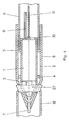
- the device according to the invention consists of a hydraulic striking device 1, a striking head 2, a switch located in the striking device with an outwardly directed plunger 3 for switching the striking device on or off, a slide ring 4 for guiding the striking device 1, and a stop ring 5 for closing a striker Tube 6, an adapter 7 with a front part for attaching a pull cable and a rear part 8 for connecting the adapter to the impact device 1, a supply and disposal line 9 of the impact device 1, a stop eye 10 for attaching a pull cable 11 for withdrawing the device against the direction of advance, an attachment head 12 for adapting the impact head to the respective function and one on the Tappet 3 abutment 13 for transmitting the ambient resistance to the switch in the impact device 1.
- the rear part of the adapter 8 is guided through bores 14 and 15 of the striking head 2 without frictional engagement and engages directly on the striking device 1, which is axially displaceably mounted in the striking head 2 via the sliding ring 4 and the stop ring 5 designed as a sliding ring.
- the plunger 3 of the switch Arranged between the end face of the striking device 1 and the abutment 13 of the striking head 2 is the plunger 3 of the switch which determines the working phases of the striking device, which is actuated indirectly via the striking device 1 by the tensile force acting on the front part of the adapter 7 via the pull rope.
- the impact device 1 is switched on above a lower threshold and switched off again below this threshold.
- connection of the pull cable to the percussion drive 1 by means of the adapter 7, 8 can be damped in the rear part of the adapter 8 by a shock-absorbing element.
- a transmitter 16 in the striking head 2 is advantageous for determining the position of the device with the aid of an above-ground receiver.
- the device is moved by means of a push tube 17, for example through a pilot bore.
- the free pipe end acts via the stop ring 5 on the impact device 1 for actuating the switch in the event of the predetermined threshold value being exceeded or undershot Way that the thrust of the tube 6 causes an axial displacement of the impact device 1 in relation to the impact head 2 and thereby actuates the switch in the impact device 1 via the plunger 3 ( Figure 2).
- the pipe 17 is located between the striking device 1 and a striking head 2, equipped with knives, not shown, designed as a bursting head, for destroying an old pipe 18 (FIG. 3).
- the plunger 3 is connected to a push rod 19 which runs inside the tube 17 and transmits the ambient resistance acting on the bursting or striking head 2 to the switch of the striking device 1 and actuates the switch when the threshold value is exceeded or fallen below.
- the impact device 1 is located on a carriage 20 with a slide 21, between which and an abutment 25 there is a thrust cylinder 26 for advancing the impact device.
- a tool 27 for destroying an old pipe 18 can be inserted into the striking head 2 and then act directly on the plunger 3.
- the adapter is guided through the tool 27 without frictional connection.
- the device can also be used for driving in pipes.
- the tube adapter 22 is located on the striking head 2.
- the striking drive 1 is activated when a certain threshold pressure is exceeded (FIG. 5).
- the striking device 1 is located in a target pit and is connected via a pull rod 23 to a striking head 2 located in a starting pit in the form of a bursting head for destroying an old pipe 18 and pulling in a new pipe 6.
- the pull rod 23 can be connected to the plunger 3, for example, via a U-piece 24 spanning the impact device.
- the driving force is transmitted from the impact device 1 via the switch plunger 3 to the impact head 2 via the pull rod 23 connected to the impact head 23 and the U-piece 24.
Landscapes
- Engineering & Computer Science (AREA)
- Geology (AREA)
- Life Sciences & Earth Sciences (AREA)
- Mining & Mineral Resources (AREA)
- Environmental & Geological Engineering (AREA)
- Fluid Mechanics (AREA)
- Physics & Mathematics (AREA)
- General Life Sciences & Earth Sciences (AREA)
- Geochemistry & Mineralogy (AREA)
- General Engineering & Computer Science (AREA)
- Mechanical Engineering (AREA)
- Excavating Of Shafts Or Tunnels (AREA)
- Earth Drilling (AREA)
Applications Claiming Priority (2)
| Application Number | Priority Date | Filing Date | Title |
|---|---|---|---|
| DE1995112602 DE19512602C1 (de) | 1995-03-31 | 1995-03-31 | Vorrichtung zum Rammen von Rohren oder zum Aufweiten von Pilotbohrungen oder Ersetzen erdverlegter Rohrleitungen |
| DE19512602 | 1995-03-31 |
Publications (2)
| Publication Number | Publication Date |
|---|---|
| EP0735231A2 true EP0735231A2 (fr) | 1996-10-02 |
| EP0735231A3 EP0735231A3 (fr) | 1997-11-19 |
Family
ID=7758757
Family Applications (1)
| Application Number | Title | Priority Date | Filing Date |
|---|---|---|---|
| EP96104100A Withdrawn EP0735231A3 (fr) | 1995-03-31 | 1996-03-15 | Dispositif d'enforcement de tubages ou d'élargissement de trous pilotes ou de remplacement d'une conduite enterrée |
Country Status (3)
| Country | Link |
|---|---|
| EP (1) | EP0735231A3 (fr) |
| JP (1) | JPH094373A (fr) |
| DE (1) | DE19512602C1 (fr) |
Cited By (1)
| Publication number | Priority date | Publication date | Assignee | Title |
|---|---|---|---|---|
| DE19817872A1 (de) * | 1998-04-22 | 1999-10-28 | Tracto Technik | Aufweitvorrichtung |
Families Citing this family (4)
| Publication number | Priority date | Publication date | Assignee | Title |
|---|---|---|---|---|
| DE10157301B4 (de) * | 2001-11-23 | 2004-11-11 | Tracto-Technik Gmbh | Druckmittelbetriebenes Erdbohrgerät und Verfahren zum Einziehen eines Produktrohrs in das Erdreich |
| DE102010004097B4 (de) | 2010-01-07 | 2019-06-19 | Tracto-Technik Gmbh & Co. Kg | Verfahren zum Sanieren eines Altrohrs sowie System zur Durchführung eines solchen Verfahrens |
| DE102012103842A1 (de) * | 2012-05-02 | 2013-11-07 | Rbs Spezialmaschinen Gmbh | Vorrichtung und Verfahren zur grabenlosen Kanalsanierung |
| DE102020206603A1 (de) * | 2020-05-27 | 2021-12-02 | Uden Spezialwerkzeuge Handels- und Dienstleistungs UG (haftungsbeschränkt) | Oszillierendes Fräswerkzeug und Verfahren zum Entfernen eines im Erdreich verlegten Rohrs |
Family Cites Families (6)
| Publication number | Priority date | Publication date | Assignee | Title |
|---|---|---|---|---|
| EP0053480B2 (fr) * | 1980-12-02 | 1992-07-29 | British Gas plc | Echange de tuyaux |
| GB2138532B (en) * | 1983-03-31 | 1987-01-28 | Daly Limited P N | Pipe replacement |
| GB2164411B (en) * | 1984-08-24 | 1987-09-03 | Water Res Centre | Pipe mole |
| DE3564003D1 (en) * | 1985-01-10 | 1988-09-01 | British Gas Corp | Mains bursting tool |
| US5282696A (en) * | 1992-10-30 | 1994-02-01 | Jim Solomon | Pneumatic ram pipe replacement |
| GB9407902D0 (en) * | 1994-04-21 | 1994-06-15 | Univ Aberdeen | Moling apparatus |
-
1995
- 1995-03-31 DE DE1995112602 patent/DE19512602C1/de not_active Expired - Fee Related
-
1996
- 1996-03-15 EP EP96104100A patent/EP0735231A3/fr not_active Withdrawn
- 1996-04-01 JP JP8101914A patent/JPH094373A/ja not_active Withdrawn
Cited By (3)
| Publication number | Priority date | Publication date | Assignee | Title |
|---|---|---|---|---|
| DE19817872A1 (de) * | 1998-04-22 | 1999-10-28 | Tracto Technik | Aufweitvorrichtung |
| US6244783B1 (en) | 1998-04-22 | 2001-06-12 | Tracto-Technik-Paul Schmidt Spezialmaschinen | Widening apparatus |
| DE19817872C2 (de) * | 1998-04-22 | 2002-08-08 | Tracto Technik | Aufweitvorrichtung |
Also Published As
| Publication number | Publication date |
|---|---|
| JPH094373A (ja) | 1997-01-07 |
| EP0735231A3 (fr) | 1997-11-19 |
| DE19512602C1 (de) | 1996-09-26 |
Similar Documents
| Publication | Publication Date | Title |
|---|---|---|
| DE2157259C3 (de) | Rammbohrgerät | |
| DE60314160T2 (de) | Verfahren und vorrichtung zum austausch von unterirdischen rohren | |
| DE3826513C2 (fr) | ||
| DE10297180B4 (de) | Schlagwerkzeug zur Verwendung mit einer Richtungsbohrmascine | |
| DE69632323T2 (de) | Vorrichtung zum ersetzen von eingegrabenen rohren | |
| DE3733463C1 (en) | Process and apparatus for exchanging pipes | |
| EP0411278B1 (fr) | Procédé et dispositif pour la destruction d'une conduite enterrée | |
| EP0953723B1 (fr) | Dispositif d'élargissement | |
| DE19512602C1 (de) | Vorrichtung zum Rammen von Rohren oder zum Aufweiten von Pilotbohrungen oder Ersetzen erdverlegter Rohrleitungen | |
| DE10146024C2 (de) | Schlagvorrichtung, Erdbohrvorrichtung und Verfahren zum Vortrieb eines Bohrkopfes oder eines Aufweitkörpers | |
| DE3124524A1 (de) | Rammkopf fuer selbstgetriebene pneumatische rammbohrgeraete | |
| WO2002044508A2 (fr) | Appareil pneumatique de forage de roches et procede de forage horizontal avec air comprime et fluide de forage | |
| EP0805258B1 (fr) | Mouton de forage réversible | |
| EP0067427A2 (fr) | Procédé d'aspiration de gaz dans les mines de charbon et tuyau d'aspiration pour réaliser ce procédé | |
| DE3903864C1 (en) | Method and apparatus for redeveloping old pipes | |
| EP0789129A2 (fr) | Mouton de forage autopropulsé | |
| DE4308547C1 (de) | Verfahren und Vorrichtung zum Verlegen von Rohren durch Pressen und gleichzeitiges Rammen | |
| DE10146023B4 (de) | Steuerung für einen Schlagantrieb | |
| EP0418720B1 (fr) | Méthode pour renouvellement à tuyaux de drainage en depôt de déchets et dispositif pour la réalisation de cette méthode | |
| DE69003455T2 (de) | Rohrberster. | |
| EP0271631B1 (fr) | Appareil pour enfoncer avec le mouton et forer | |
| DE4021719A1 (de) | Vorrichtung zum erweitern einer im erdreich hergestellten pilotbohrung | |
| DE10157301B4 (de) | Druckmittelbetriebenes Erdbohrgerät und Verfahren zum Einziehen eines Produktrohrs in das Erdreich | |
| DE10332328B3 (de) | Vorrichtung zum Erneuern von im Erdreich verlegten Versorgungsleitungen | |
| DE2748961A1 (de) | Tiefbohr-vorrichtung |
Legal Events
| Date | Code | Title | Description |
|---|---|---|---|
| PUAI | Public reference made under article 153(3) epc to a published international application that has entered the european phase |
Free format text: ORIGINAL CODE: 0009012 |
|
| AK | Designated contracting states |
Kind code of ref document: A2 Designated state(s): CH FR GB LI |
|
| PUAL | Search report despatched |
Free format text: ORIGINAL CODE: 0009013 |
|
| AK | Designated contracting states |
Kind code of ref document: A3 Designated state(s): CH FR GB LI |
|
| 17P | Request for examination filed |
Effective date: 19980228 |
|
| STAA | Information on the status of an ep patent application or granted ep patent |
Free format text: STATUS: THE APPLICATION IS DEEMED TO BE WITHDRAWN |
|
| 18D | Application deemed to be withdrawn |
Effective date: 20001003 |