EP0735355A2 - Dispositif de fixation de corps de révolution à équilibrer, en particulier des roues de véhicule, sur l'arbre principal d'une machine d'équilibrage - Google Patents
Dispositif de fixation de corps de révolution à équilibrer, en particulier des roues de véhicule, sur l'arbre principal d'une machine d'équilibrage Download PDFInfo
- Publication number
- EP0735355A2 EP0735355A2 EP96101366A EP96101366A EP0735355A2 EP 0735355 A2 EP0735355 A2 EP 0735355A2 EP 96101366 A EP96101366 A EP 96101366A EP 96101366 A EP96101366 A EP 96101366A EP 0735355 A2 EP0735355 A2 EP 0735355A2
- Authority
- EP
- European Patent Office
- Prior art keywords
- main shaft
- clamping device
- pressure element
- centering
- clamping
- Prior art date
- Legal status (The legal status is an assumption and is not a legal conclusion. Google has not performed a legal analysis and makes no representation as to the accuracy of the status listed.)
- Granted
Links
Images

Classifications
-
- G—PHYSICS
- G01—MEASURING; TESTING
- G01M—TESTING STATIC OR DYNAMIC BALANCE OF MACHINES OR STRUCTURES; TESTING OF STRUCTURES OR APPARATUS, NOT OTHERWISE PROVIDED FOR
- G01M1/00—Testing static or dynamic balance of machines or structures
- G01M1/02—Details of balancing machines or devices
- G01M1/04—Adaptation of bearing support assemblies for receiving the body to be tested
- G01M1/045—Adaptation of bearing support assemblies for receiving the body to be tested the body being a vehicle wheel
Definitions
- the invention relates to a clamping device for clamping rotating bodies to be balanced, in particular motor vehicle wheels, on a main shaft of a balancing machine with the features of the preamble of claim 1.
- Such a clamping device is known from DE-OS 24 24 668.
- a motor vehicle wheel is clamped centrally on a balancing machine by centering it with its central rim opening through a centering cone on the main shaft and clamping it against a contact flange.
- the clamping force required for this is applied by a clamping screw which can be screwed onto the main shaft and which is provided with handles for operation by an operator.
- a clamping screw which can be screwed onto the main shaft and which is provided with handles for operation by an operator.
- it is disadvantageous that the entire required clamping force has to be applied by the operator by means of the screw connection by hand and that considerable force is required to loosen the clamping screw.
- the invention is therefore based on the object of further developing a generic tensioning device in such a way that an operator is relieved when clamping a rotary body or a motor vehicle wheel to be balanced.
- the axial displaceability of the contact flange enables the required clamping force to be applied to the rotating body via the movement of the contact flange.
- an actuating device for displacing the contact flange which offers mechanical force generation, there is the advantage that an operator no longer has to apply the comparatively large clamping force by hand, but only the lower centering force required when pressing the pressure element against the rotating body is.
- Any device that acts on the contact flange and moves it axially is suitable as an actuating device. It expediently contains at least one axial expansion element attached to the main shaft. Such an element is also suitable for retrofitting existing balancing machines of a simpler design that do not yet have any mechanically operable actuating devices, such as, for example, in balancing machines with a tie rod in an axial bore in the main shaft, with which the pressure element can be actuated.
- a particularly simple and suitable actuating device is a pneumatically actuated air bellows.
- the clamping force can thus be generated quickly and safely.
- the necessary compressed air supply is available in workshops or it can be generated with an electric compressor.
- a hydraulic element with hydraulic actuation or a mechanically operable axial expansion element e.g. with a spindle
- One or more axial expansion elements can be used be distributed around the circumference of the main shaft or an annular axial expansion element, in particular an annular air bellows, is attached around the main shaft. If this is rotatably mounted on the main shaft, the air supply line is easier to design than with a rotating air bellows, which requires a special air connection element.
- the tensioning device preferably contains a sleeve on which some or all components of the tensioning device are attached.
- This tensioning device can be easily attached to existing main shafts of balancing machines without having to make adjustments to the main shaft.
- standardized components of the clamping device can also be used for main shafts with different dimensions or designs.
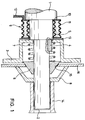
- a balancing machine has a main shaft 1 with a free shaft end 2.
- the main shaft 1 can be driven in a known manner to carry out a balancing process and is provided with suitable force measuring devices for detecting an unbalance.
- a contact flange 3 is on the main shaft 1 axially displaceable and in the circumferential direction, for. B. by a spline 4, rotatably mounted. In the direction of the balancing machine (to the left in FIG. 1), the contact flange 3 is axially supported on a shoulder 5, a collar or the like.
- a centering cone 6 is guided radially free of play on the main shaft 1 and is spring-elastically supported in the direction of the balancing machine by a spiral spring 7, which can be supported on the contact flange 3.
- a pressure pot 8 can be arranged and fixed on the main shaft 1 via the free shaft end 2. The determination can be made in that the pressure pot 8, the z. B. is connected to a threaded sleeve 14, with this screwed onto an external thread (not shown) on the main shaft 1 and blocked against loosening.
- the pressure pot 8 can also be fixed by a bayonet lock (not shown) or by a separate clamping or latching device, such as, for example, by a quick-lock nut 17 (FIG. 2), which has locking elements which, after the nut 17 has been slid axially onto the free one Shaft end 2 of the main shaft 1 interlockingly engage in a thread 18 on the main shaft 1 and can be released again by actuating an unlocking mechanism.
- an actuating device 9 is arranged on the main shaft 1 between the contact flange 3 and a machine shoulder 10 of the main shaft 1.
- the actuating device 9 is, for example, an axial expansion element which is designed as an annular air bellows 11 which has an air connection 12 for pneumatic actuation. Air supply expands the air bellows 11 axially and, since it is supported on the shaft shoulder 10, exerts an axial compressive force and a displacement movement on the contact flange 3.
- the air bellows 11 can be rotatably mounted on the main shaft 1 so that it does not co-rotate with the main shaft 1 when it rotates. Then the air connection 12 can be formed as a simple feed line. Since the contact flange 3 rotates with the main shaft 1, an axial force-transmitting movement compensation element 13 (shown schematically, for example an axial bearing) for compensating the relative movements is arranged between the air bellows 11 and the contact flange 3.
- the air bellows 11 is then pressurized by pneumatic actuation, ie by air supply, to which it reacts by axial expansion or extension.
- pneumatic actuation ie by air supply
- the contact flange 3 is displaced against the rim 16 of the motor vehicle wheel held between the pressure pot 8 and the centering cone 6, its Centering on the centering cone 6 held axially under spring tension is retained.
- the rim 16 is now pressed against the pressure pot 8 with the required clamping or clamping force, so that the motor vehicle wheel is fastened in a sufficiently rotationally fixed manner for its rotation and acceleration during balancing with respect to the main shaft 1.
- the clamping device described can be arranged in whole or in part (with air bellows) on a sleeve which can be attached and fixed on a main shaft.
- the sleeve contains the devices for the rotationally fixed fixing of the contact flange (by means of splined shaft, multiple spline or any positive locking profile) and / or for fixing the pressure pot (e.g. via a lock nut with a bayonet lock, a screwable nut for engagement with an external thread on the Sleeve or through a quick release nut).
Landscapes
- Physics & Mathematics (AREA)
- General Physics & Mathematics (AREA)
- Testing Of Balance (AREA)
Applications Claiming Priority (2)
| Application Number | Priority Date | Filing Date | Title |
|---|---|---|---|
| DE19511405A DE19511405A1 (de) | 1995-03-28 | 1995-03-28 | Spannvorrichtung zum Aufspannen von auszuwuchtenden Rotationskörpern, insbesondere von Kraftfahrzeugrädern, auf einer Hauptwelle einer Auswuchtmaschine |
| DE19511405 | 1995-03-28 |
Publications (3)
| Publication Number | Publication Date |
|---|---|
| EP0735355A2 true EP0735355A2 (fr) | 1996-10-02 |
| EP0735355A3 EP0735355A3 (fr) | 1997-11-05 |
| EP0735355B1 EP0735355B1 (fr) | 2001-08-16 |
Family
ID=7757990
Family Applications (1)
| Application Number | Title | Priority Date | Filing Date |
|---|---|---|---|
| EP96101366A Expired - Lifetime EP0735355B1 (fr) | 1995-03-28 | 1996-01-31 | Dispositif de fixation de corps de révolution à équilibrer, en particulier des roues de véhicule, sur l'arbre principal d'une machine d'équilibrage |
Country Status (4)
| Country | Link |
|---|---|
| US (1) | US5703291A (fr) |
| EP (1) | EP0735355B1 (fr) |
| DE (1) | DE19511405A1 (fr) |
| ES (1) | ES2161925T3 (fr) |
Cited By (1)
| Publication number | Priority date | Publication date | Assignee | Title |
|---|---|---|---|---|
| WO2008107144A1 (fr) * | 2007-03-03 | 2008-09-12 | Haweka Ag | Bride de serrage |
Families Citing this family (9)
| Publication number | Priority date | Publication date | Assignee | Title |
|---|---|---|---|---|
| IT1287823B1 (it) * | 1996-09-06 | 1998-08-19 | Femas Srl | Dispositivo automatico di bloccaggio delle ruote di automezzi in genere sugli alberi delle macchine equilibratrici |
| DE10238271B4 (de) * | 2002-08-21 | 2012-11-08 | Snap-On Equipment Gmbh | Verfahren und Vorrichtung zum zentrierten Spannen eines Kraftfahrzeugrades auf eine Hauptwelle einer Radauswuchtmaschine |
| ITRE20020074A1 (it) * | 2002-10-02 | 2004-04-03 | Corghi Spa | Gruppo di bloccaggio e trascinamento di un corpo rotante, |
| DE102004044287B3 (de) | 2004-09-10 | 2005-08-25 | Warkotsch, Horst | Schnellspannvorrichtung mit Mittenzentrierung zur Befestigung eines Fahrzeugrades auf der Welle einer Auswuchtmaschine |
| DE102004044470B4 (de) * | 2004-09-15 | 2006-11-09 | Bayerische Motoren Werke Ag | Wuchtanlage zum statischen Auswuchten von luftbereiften Fahrzeugrädern, insbesondere von luftbereiften Leichtmetallrädern |
| US20060266105A1 (en) * | 2005-05-16 | 2006-11-30 | Hunter Engineering Company | Wheel balancer system with automatic wheel clamping and wheel centering |
| US8069675B2 (en) * | 2006-10-10 | 2011-12-06 | Massachusetts Institute Of Technology | Cryogenic vacuum break thermal coupler |
| JP5974370B2 (ja) | 2013-03-18 | 2016-08-23 | 株式会社Ihi | 回転機械支持装置 |
| ES2634675T3 (es) * | 2015-05-20 | 2017-09-28 | Corghi S.P.A. | Máquina de equilibrado |
Family Cites Families (11)
| Publication number | Priority date | Publication date | Assignee | Title |
|---|---|---|---|---|
| US3152484A (en) * | 1961-02-17 | 1964-10-13 | George T Hemmeter | Positioner for a wheel balancer |
| US3165932A (en) * | 1963-04-19 | 1965-01-19 | Bishman Mfg Company | Adapter for wheel balancer |
| US3889542A (en) * | 1973-11-09 | 1975-06-17 | Fmc Corp | Wheel mounting apparatus |
| DE7417691U (fr) * | 1974-05-21 | 1974-09-05 | Warkotsch H | |
| US4005607A (en) * | 1975-11-20 | 1977-02-01 | Fmc Corporation | Static wheel balancer |
| US4229977A (en) * | 1976-07-28 | 1980-10-28 | Autodynamics, Inc. | Tire balancing machine system |
| US4118989A (en) * | 1977-02-22 | 1978-10-10 | Wyle Laboratories | Locking mechanism |
| FR2497949A1 (fr) * | 1981-01-09 | 1982-07-16 | Muller & Cie Ets M | Nez d'equilibreuse de roues de vehicules |
| DE3400505A1 (de) * | 1984-01-10 | 1985-07-18 | Drägerwerk AG, 2400 Lübeck | Atemschutzgeraet mit schutzhaube |
| US4864859A (en) * | 1988-07-25 | 1989-09-12 | Allied-Signal Inc. | Method for dynamically balancing a mechanism having a high speed rotating component |
| DE9205071U1 (de) * | 1992-04-11 | 1992-06-17 | Warkotsch, Horst, 3006 Burgwedel | Schnellspannvorrichtung mit Mittenzentrierung zur Befestigung eines Fahrzeugrades auf der Achse einer Auswuchtmaschine |
-
1995
- 1995-03-28 DE DE19511405A patent/DE19511405A1/de not_active Withdrawn
-
1996
- 1996-01-31 EP EP96101366A patent/EP0735355B1/fr not_active Expired - Lifetime
- 1996-01-31 ES ES96101366T patent/ES2161925T3/es not_active Expired - Lifetime
- 1996-03-12 US US08/614,245 patent/US5703291A/en not_active Expired - Fee Related
Cited By (1)
| Publication number | Priority date | Publication date | Assignee | Title |
|---|---|---|---|---|
| WO2008107144A1 (fr) * | 2007-03-03 | 2008-09-12 | Haweka Ag | Bride de serrage |
Also Published As
| Publication number | Publication date |
|---|---|
| DE19511405A1 (de) | 1996-10-02 |
| EP0735355A3 (fr) | 1997-11-05 |
| US5703291A (en) | 1997-12-30 |
| EP0735355B1 (fr) | 2001-08-16 |
| ES2161925T3 (es) | 2001-12-16 |
Similar Documents
| Publication | Publication Date | Title |
|---|---|---|
| DE3936458C1 (fr) | ||
| DE3814831C1 (fr) | ||
| EP0735355A2 (fr) | Dispositif de fixation de corps de révolution à équilibrer, en particulier des roues de véhicule, sur l'arbre principal d'une machine d'équilibrage | |
| DE2935216C2 (de) | Schnellspannmutter, insbesondere zur Befestigung eines Kraftfahrzeugrades auf der Aufspannwelle einer Auswuchtmaschine | |
| EP1155829B1 (fr) | Elément de cylindre interchangeable dans une unité d'impression électrographique | |
| EP1310360B1 (fr) | Machine d'impression flexographique avec des cylindres de transfert d'encre applicables de façon manuelle et automatique | |
| DE4336508C2 (de) | Verfahren und Vorrichtung zum Inpositionhalten eines auf einer Meßspindel einer Auswuchtmaschine aufgespannten Kraftfahrzeugrades | |
| EP1635159A2 (fr) | Dispositif de fixation rapide avec moyen de centrage d'une roue de véhicule sur une broche d'une machine d'équilibrage. | |
| CH622463A5 (fr) | ||
| EP0719640B1 (fr) | Cylindre pour une machine à imprimer rotative | |
| DE10238271B4 (de) | Verfahren und Vorrichtung zum zentrierten Spannen eines Kraftfahrzeugrades auf eine Hauptwelle einer Radauswuchtmaschine | |
| DE3603561C1 (de) | Einrichtung zum automatischen Verstellen einer Stangenfuehrung an einer numerisch gesteuerten Drehmaschine | |
| DE19850569C1 (de) | Maschinenspindel | |
| DE102014113729B4 (de) | Wellenmessverfahren | |
| DE3410689C2 (fr) | ||
| DE2616945B2 (de) | Vorrichtung zum Aufspannen von Kraftfahrzeugrädern | |
| DE3708380C2 (de) | Zentrierdorn für Kupplungsscheiben und Verfahren zur Messung des Seitenschlages | |
| DE19940109A1 (de) | Vorrichtung zum Befestigen einer Ausgleichshülse auf einer Klischeezylinderwelle einer Druckmaschine | |
| DE2737224C2 (de) | Spannfutter | |
| DE102004041590B3 (de) | Spann- und Dreheinrichtung zum Vermessen eines Kraftfahrzeugrades mit Mittelloch | |
| DE496509C (de) | Werkzeug zur Bearbeitung zylindrischer Innenflaechen mit mehreren durch Stellkonus zwecks Beistellung radial verstellbaren Schleifbacken | |
| EP0051137A1 (fr) | Dispositif pour ajuster un régulateur de force de freinage commandé mécaniquement | |
| DE2027200C3 (de) | Vorrichtung zum Aufspannen eines Druckzylinders | |
| DE3149600C2 (de) | Vorrichtung zur Betätigung der Schaltpunkte mindestens eines Schalters für die Wegkontrolle von umlaufenden Spanneinrichtungen wie Spannfutter od. dgl. | |
| DE3820871A1 (de) | Vorrichtung zum fuegen und festspannen von spannmitteln an werkzeugmaschinenspindeln |
Legal Events
| Date | Code | Title | Description |
|---|---|---|---|
| PUAI | Public reference made under article 153(3) epc to a published international application that has entered the european phase |
Free format text: ORIGINAL CODE: 0009012 |
|
| AK | Designated contracting states |
Kind code of ref document: A2 Designated state(s): ES FR GB IT |
|
| RBV | Designated contracting states (corrected) |
Designated state(s): ES FR GB IT |
|
| REG | Reference to a national code |
Ref country code: DE Ref legal event code: 8566 |
|
| PUAL | Search report despatched |
Free format text: ORIGINAL CODE: 0009013 |
|
| AK | Designated contracting states |
Kind code of ref document: A3 Designated state(s): ES FR GB IT |
|
| 17P | Request for examination filed |
Effective date: 19980403 |
|
| 17Q | First examination report despatched |
Effective date: 19990708 |
|
| GRAG | Despatch of communication of intention to grant |
Free format text: ORIGINAL CODE: EPIDOS AGRA |
|
| GRAH | Despatch of communication of intention to grant a patent |
Free format text: ORIGINAL CODE: EPIDOS IGRA |
|
| RAP1 | Party data changed (applicant data changed or rights of an application transferred) |
Owner name: SNAP-ON DEUTSCHLAND HOLDING GMBH |
|
| GRAG | Despatch of communication of intention to grant |
Free format text: ORIGINAL CODE: EPIDOS AGRA |
|
| GRAG | Despatch of communication of intention to grant |
Free format text: ORIGINAL CODE: EPIDOS AGRA |
|
| GRAH | Despatch of communication of intention to grant a patent |
Free format text: ORIGINAL CODE: EPIDOS IGRA |
|
| GRAH | Despatch of communication of intention to grant a patent |
Free format text: ORIGINAL CODE: EPIDOS IGRA |
|
| GRAA | (expected) grant |
Free format text: ORIGINAL CODE: 0009210 |
|
| AK | Designated contracting states |
Kind code of ref document: B1 Designated state(s): ES FR GB IT |
|
| GBT | Gb: translation of ep patent filed (gb section 77(6)(a)/1977) |
Effective date: 20010816 |
|
| REG | Reference to a national code |
Ref country code: ES Ref legal event code: FG2A Ref document number: 2161925 Country of ref document: ES Kind code of ref document: T3 |
|
| REG | Reference to a national code |
Ref country code: GB Ref legal event code: IF02 |
|
| ET | Fr: translation filed | ||
| PGFP | Annual fee paid to national office [announced via postgrant information from national office to epo] |
Ref country code: FR Payment date: 20020110 Year of fee payment: 7 |
|
| PGFP | Annual fee paid to national office [announced via postgrant information from national office to epo] |
Ref country code: GB Payment date: 20020115 Year of fee payment: 7 |
|
| PGFP | Annual fee paid to national office [announced via postgrant information from national office to epo] |
Ref country code: ES Payment date: 20020116 Year of fee payment: 7 |
|
| PLBE | No opposition filed within time limit |
Free format text: ORIGINAL CODE: 0009261 |
|
| STAA | Information on the status of an ep patent application or granted ep patent |
Free format text: STATUS: NO OPPOSITION FILED WITHIN TIME LIMIT |
|
| 26N | No opposition filed | ||
| PG25 | Lapsed in a contracting state [announced via postgrant information from national office to epo] |
Ref country code: GB Free format text: LAPSE BECAUSE OF NON-PAYMENT OF DUE FEES Effective date: 20030131 |
|
| PG25 | Lapsed in a contracting state [announced via postgrant information from national office to epo] |
Ref country code: ES Free format text: LAPSE BECAUSE OF NON-PAYMENT OF DUE FEES Effective date: 20030201 |
|
| GBPC | Gb: european patent ceased through non-payment of renewal fee | ||
| PG25 | Lapsed in a contracting state [announced via postgrant information from national office to epo] |
Ref country code: FR Free format text: LAPSE BECAUSE OF NON-PAYMENT OF DUE FEES Effective date: 20030930 |
|
| REG | Reference to a national code |
Ref country code: FR Ref legal event code: ST |
|
| REG | Reference to a national code |
Ref country code: ES Ref legal event code: FD2A Effective date: 20030201 |
|
| PG25 | Lapsed in a contracting state [announced via postgrant information from national office to epo] |
Ref country code: IT Free format text: LAPSE BECAUSE OF NON-PAYMENT OF DUE FEES Effective date: 20050131 |