EP0735355B1 - Dispositif de fixation de corps de révolution à équilibrer, en particulier des roues de véhicule, sur l'arbre principal d'une machine d'équilibrage - Google Patents
Dispositif de fixation de corps de révolution à équilibrer, en particulier des roues de véhicule, sur l'arbre principal d'une machine d'équilibrage Download PDFInfo
- Publication number
- EP0735355B1 EP0735355B1 EP96101366A EP96101366A EP0735355B1 EP 0735355 B1 EP0735355 B1 EP 0735355B1 EP 96101366 A EP96101366 A EP 96101366A EP 96101366 A EP96101366 A EP 96101366A EP 0735355 B1 EP0735355 B1 EP 0735355B1
- Authority
- EP
- European Patent Office
- Prior art keywords
- main shaft
- clamping apparatus
- centering
- rotary body
- sleeve
- Prior art date
- Legal status (The legal status is an assumption and is not a legal conclusion. Google has not performed a legal analysis and makes no representation as to the accuracy of the status listed.)
- Expired - Lifetime
Links
- 230000006978 adaptation Effects 0.000 claims 1
- 230000001133 acceleration Effects 0.000 description 1
- 230000001419 dependent effect Effects 0.000 description 1
- 238000000034 method Methods 0.000 description 1
- 230000000717 retained effect Effects 0.000 description 1
- 238000009420 retrofitting Methods 0.000 description 1
Images

Classifications
-
- G—PHYSICS
- G01—MEASURING; TESTING
- G01M—TESTING STATIC OR DYNAMIC BALANCE OF MACHINES OR STRUCTURES; TESTING OF STRUCTURES OR APPARATUS, NOT OTHERWISE PROVIDED FOR
- G01M1/00—Testing static or dynamic balance of machines or structures
- G01M1/02—Details of balancing machines or devices
- G01M1/04—Adaptation of bearing support assemblies for receiving the body to be tested
- G01M1/045—Adaptation of bearing support assemblies for receiving the body to be tested the body being a vehicle wheel
Definitions
- the invention relates to a clamping device for clamping of rotating bodies to be balanced, in particular of Motor vehicle wheels, on a main shaft of a balancing machine with the features of the preamble of claim 1.
- the object of the invention is to provide a clamping device at the beginning to create the type mentioned, in which with simple Averaged by the operator when attaching the rotating body force to be applied is reduced.
- the one used in the axial direction pneumatically expandable element is also suitable for retrofitting existing balancing machines of simpler design, the still no mechanically operated actuators have, such as with balancing machines a tie rod in an axial bore of the main shaft.
- the air bellows is a particularly simple and suitable one Actuator with which the clamping force is quick and can be generated safely.
- the required compressed air supply is available in workshops or can be used with one electric compressor are generated.
- an annular one Air bellows is attached around the main shaft. If this is rotatably mounted on the main shaft, to make the air supply easier than with a rotating one Air bellows, which is a special air connection element needed.
- the tensioning device preferably contains a sleeve some or all of the components of the jig are attached are.
- This jig can be easily mount on existing main shafts of balancing machines, without making adjustments to the main shaft should be.
- With a compensating sleeve standardized Components of the tensioning device also for main shafts used with different dimensions or designs become.
- a balancing machine has a main shaft 1 with a free shaft end 2.
- the main shaft 1 is to be carried out of a balancing process can be driven in a known manner and with suitable force measuring devices for detecting a Provided unbalance.
- a contact flange 3 is on the main shaft 1 axially displaceable and in the circumferential direction, for. B. through a keyway profile 4, rotatably mounted. In the direction to the balancing machine (to the left in Figure 1) is supported the contact flange 3 on a shoulder 5, a collar or the like axially.
- a centering cone 6 is on the main shaft 1 guided radially without play and by a spiral spring 7, which can be supported on the contact flange 3, resilient supported towards the balancing machine.
- a pressure pot 8 on the free shaft end 2 Main shaft 1 can be arranged and fixed.
- the definition can be done in that the pressure pot 8, the z. B. is connected to a threaded sleeve 14 with this on an external thread (not shown) on the main shaft 1 screwed and blocked against loosening.
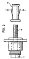
- the Pressure pot 8 can also by a bayonet lock (not shown) or by a separate clamping or locking device such as a Quick release nut 17 (Fig. 2), which has locking elements, after the axial sliding on of the nut 17 locking the free shaft end 2 of the main shaft 1 into one Engage thread 18 on the main shaft 1 and by actuation unlocking can be released again.
- an actuator 9 is on the Main shaft 1 between the contact flange 3 and a machine side Shaft shoulder 10 of the main shaft 1 arranged.
- the actuating device 9 is, for example, a axial expansion element that acts as an annular bellows 11 is executed, the air connection 12 for pneumatic Has actuation. Expanded by air supply the air bellows 11 axially and exercises because it is on the shaft shoulder 10 supports, an axial pressure force and a sliding movement on the contact flange 3.
- the air bellows 11 can be rotatably supported on the main shaft 1 be so that when the main shaft 1 rotates with it not rotating. Then the air connection 12 can be as simple Supply line must be formed. Since the contact flange 3 rotates with the main shaft 1, is between the air bellows 11th and the contact flange 3 an axial force-transmitting movement compensation element 13 (shown schematically, e.g. an axial bearing) arranged to compensate for the relative movements.
- the main shaft 1 of the balancing machine becomes this with its central rim opening 15 from the shaft end 2 pushed onto the main shaft 1 and onto the centering cone 6 created so that this in the rim opening 15 engages pre-centering.
- the pressure pot 8 is on the Main shaft 1 attached and in the axial direction against the Rotating body or the rim 16 moves until it on the centering cone, which is axially supported by the spring 7 in a spring-elastic manner 6 centered.
- the rim 16 is still there not on the contact flange 3.
- the pressure pot 8 is in this position on the main shaft 1 (by clamping, Detent or bayonet lock). To lay down for the centering is done by the operator by hand Applying force that is much less than that for the clamping or clamping of the rotating body required Force.
- the air bellows 11 is then pneumatically actuated, d. H. pressurized by air supply which he reacts by axial extension or extension. Due to this axial expansion, the contact flange 3 against the rim 16 between the pressure pot 8 and the centering cone 6 held motor vehicle wheel shifted, his Centering on the axially held under spring tension Centering cone 6 is retained. Depending on the The rim 16 is now pneumatically adjustable axial force with the required clamping or clamping force against the Pressure pot 8 pressed so that the motor vehicle wheel for his Rotation and acceleration when balancing the Main shaft 1 is sufficiently secured against rotation.
- the clamping device described can be partial or total (with air bellows) on a sleeve, the can be attached and fixed on a main shaft.
- the sleeve contains the devices for non-rotatable fixing of the contact flange (by means of Splined shaft, splined profile or any positive locking profile) and or to set the pressure pot (e.g. via a lock nut with a bayonet lock, a screwable one Nut for engagement with an external thread on the sleeve or with a quick release nut).
Landscapes
- Physics & Mathematics (AREA)
- General Physics & Mathematics (AREA)
- Testing Of Balance (AREA)
Claims (8)
- Dispositif de blocage destiné à bloquer des corps de révolution à équilibrer, notamment des roues de véhicule automobile sur un arbre (1) principal d'une machine d'équilibrage, comprenant un cône (6) de centrage qui est soutenu, avec une élasticité de ressort axialement, sur l'arbre principal et qui est destiné à centrer le corps (16) de révolution par rapport à l'arbre (1) principal,comprenant un élément (8) de pression pouvant être fixé sur l'arbre (1) principal et destiné à repousser le corps de révolution sur le cône (6) de centrage pour le mettre dans une position de centrage ;comprenant une bride (3) d'appui qui est montée, sans possibilité de tourner mais avec possibilité de coulissement axial pour la fixation de la pièce (6) de révolution contre l'élément (8) de pression, sur l'arbre (1) principal et qui peut être repoussée par un dispositif (9) d'actionnement vers le corps (16) de révolution maintenu centré, caractérisé en ce que le dispositif (9) d'actionnement comporte au moins un soufflet (11) d'air pouvant être monté sur l'arbre (1) principal et pouvant s'expanser pneumatiquement en direction axiale.
- Dispositif de blocage suivant la revendication 1, caractérisé en ce que le soufflet (11) d'air est annulaire et est monté sur le pourtour de l'arbre (1) principal.
- Dispositif de blocage suivant la revendication 2, caractérisé en ce que le soufflet (11) d'air est monté avec possibilité de tourner sur l'arbre (1) principal.
- Dispositif de blocage suivant l'une des revendications 1 à 3,
caractérisé en ce que le l'élément (8) de pression est en forme de boíte. - Dispositif de blocage suivant l'une des revendications 1 à 4, caractérisé en ce que le corps (16) de révolution est une roue de véhicule automobile ayant une jante à ouverture centrale de centrage.
- Dispositif de blocage suivant l'une des revendications 1 à 4, caractérisé en ce qu'il est prévu un manchon sur lequel sont montés la bride (3) d'appui et le cône (6) de centrage et l'élément (8) de pression et qui peut être fixé sur l'arbre (1) principal.
- Dispositif de blocage suivant la revendication 6, caractérisé en ce que le soufflet (11) d'air est monté sur le manchon.
- Dispositif de blocage suivant la revendication 6 ou 7, caractérisé en ce que le manchon est un manchon de compensation destiné à s'adapter à des arbres principaux qui sont différents.
Applications Claiming Priority (2)
| Application Number | Priority Date | Filing Date | Title |
|---|---|---|---|
| DE19511405A DE19511405A1 (de) | 1995-03-28 | 1995-03-28 | Spannvorrichtung zum Aufspannen von auszuwuchtenden Rotationskörpern, insbesondere von Kraftfahrzeugrädern, auf einer Hauptwelle einer Auswuchtmaschine |
| DE19511405 | 1995-03-28 |
Publications (3)
| Publication Number | Publication Date |
|---|---|
| EP0735355A2 EP0735355A2 (fr) | 1996-10-02 |
| EP0735355A3 EP0735355A3 (fr) | 1997-11-05 |
| EP0735355B1 true EP0735355B1 (fr) | 2001-08-16 |
Family
ID=7757990
Family Applications (1)
| Application Number | Title | Priority Date | Filing Date |
|---|---|---|---|
| EP96101366A Expired - Lifetime EP0735355B1 (fr) | 1995-03-28 | 1996-01-31 | Dispositif de fixation de corps de révolution à équilibrer, en particulier des roues de véhicule, sur l'arbre principal d'une machine d'équilibrage |
Country Status (4)
| Country | Link |
|---|---|
| US (1) | US5703291A (fr) |
| EP (1) | EP0735355B1 (fr) |
| DE (1) | DE19511405A1 (fr) |
| ES (1) | ES2161925T3 (fr) |
Families Citing this family (10)
| Publication number | Priority date | Publication date | Assignee | Title |
|---|---|---|---|---|
| IT1287823B1 (it) * | 1996-09-06 | 1998-08-19 | Femas Srl | Dispositivo automatico di bloccaggio delle ruote di automezzi in genere sugli alberi delle macchine equilibratrici |
| DE10238271B4 (de) * | 2002-08-21 | 2012-11-08 | Snap-On Equipment Gmbh | Verfahren und Vorrichtung zum zentrierten Spannen eines Kraftfahrzeugrades auf eine Hauptwelle einer Radauswuchtmaschine |
| ITRE20020074A1 (it) * | 2002-10-02 | 2004-04-03 | Corghi Spa | Gruppo di bloccaggio e trascinamento di un corpo rotante, |
| DE102004044287B3 (de) | 2004-09-10 | 2005-08-25 | Warkotsch, Horst | Schnellspannvorrichtung mit Mittenzentrierung zur Befestigung eines Fahrzeugrades auf der Welle einer Auswuchtmaschine |
| DE102004044470B4 (de) * | 2004-09-15 | 2006-11-09 | Bayerische Motoren Werke Ag | Wuchtanlage zum statischen Auswuchten von luftbereiften Fahrzeugrädern, insbesondere von luftbereiften Leichtmetallrädern |
| US20060266105A1 (en) * | 2005-05-16 | 2006-11-30 | Hunter Engineering Company | Wheel balancer system with automatic wheel clamping and wheel centering |
| US8069675B2 (en) * | 2006-10-10 | 2011-12-06 | Massachusetts Institute Of Technology | Cryogenic vacuum break thermal coupler |
| DE102007010836B4 (de) * | 2007-03-03 | 2008-10-30 | Haweka Ag | Spannflansch |
| JP5974370B2 (ja) | 2013-03-18 | 2016-08-23 | 株式会社Ihi | 回転機械支持装置 |
| ES2634675T3 (es) * | 2015-05-20 | 2017-09-28 | Corghi S.P.A. | Máquina de equilibrado |
Family Cites Families (11)
| Publication number | Priority date | Publication date | Assignee | Title |
|---|---|---|---|---|
| US3152484A (en) * | 1961-02-17 | 1964-10-13 | George T Hemmeter | Positioner for a wheel balancer |
| US3165932A (en) * | 1963-04-19 | 1965-01-19 | Bishman Mfg Company | Adapter for wheel balancer |
| US3889542A (en) * | 1973-11-09 | 1975-06-17 | Fmc Corp | Wheel mounting apparatus |
| DE7417691U (fr) * | 1974-05-21 | 1974-09-05 | Warkotsch H | |
| US4005607A (en) * | 1975-11-20 | 1977-02-01 | Fmc Corporation | Static wheel balancer |
| US4229977A (en) * | 1976-07-28 | 1980-10-28 | Autodynamics, Inc. | Tire balancing machine system |
| US4118989A (en) * | 1977-02-22 | 1978-10-10 | Wyle Laboratories | Locking mechanism |
| FR2497949A1 (fr) * | 1981-01-09 | 1982-07-16 | Muller & Cie Ets M | Nez d'equilibreuse de roues de vehicules |
| DE3400505A1 (de) * | 1984-01-10 | 1985-07-18 | Drägerwerk AG, 2400 Lübeck | Atemschutzgeraet mit schutzhaube |
| US4864859A (en) * | 1988-07-25 | 1989-09-12 | Allied-Signal Inc. | Method for dynamically balancing a mechanism having a high speed rotating component |
| DE9205071U1 (de) * | 1992-04-11 | 1992-06-17 | Warkotsch, Horst, 3006 Burgwedel | Schnellspannvorrichtung mit Mittenzentrierung zur Befestigung eines Fahrzeugrades auf der Achse einer Auswuchtmaschine |
-
1995
- 1995-03-28 DE DE19511405A patent/DE19511405A1/de not_active Withdrawn
-
1996
- 1996-01-31 EP EP96101366A patent/EP0735355B1/fr not_active Expired - Lifetime
- 1996-01-31 ES ES96101366T patent/ES2161925T3/es not_active Expired - Lifetime
- 1996-03-12 US US08/614,245 patent/US5703291A/en not_active Expired - Fee Related
Also Published As
| Publication number | Publication date |
|---|---|
| DE19511405A1 (de) | 1996-10-02 |
| EP0735355A3 (fr) | 1997-11-05 |
| US5703291A (en) | 1997-12-30 |
| ES2161925T3 (es) | 2001-12-16 |
| EP0735355A2 (fr) | 1996-10-02 |
Similar Documents
| Publication | Publication Date | Title |
|---|---|---|
| EP0553104B1 (fr) | Frein a disque pour vehicules, en particulier pour vehicules routiers | |
| EP2090432B1 (fr) | Cylindre pour une unité d'impression et procédé d'échange d'un manchon d'impression d'un tel cylindre | |
| DE69815115T2 (de) | Druckmaschine mit veränderlichem abstellmechanismus | |
| EP0735355B1 (fr) | Dispositif de fixation de corps de révolution à équilibrer, en particulier des roues de véhicule, sur l'arbre principal d'une machine d'équilibrage | |
| DE3936458C1 (fr) | ||
| EP0248917A1 (fr) | Dispositif de réglage de la course du coulisseau dans une presse à arbre à excentrique | |
| EP0340452B1 (fr) | Dispositif de réglage en rotation d'un cylindre d'un dispositif de retournement et dispositif de déplacement axial d'un élément de réglage pour le changement de la position des pinces de ce cylindre dans une rotative d'impression de feuilles | |
| EP1155829B1 (fr) | Elément de cylindre interchangeable dans une unité d'impression électrographique | |
| DE2935216C2 (de) | Schnellspannmutter, insbesondere zur Befestigung eines Kraftfahrzeugrades auf der Aufspannwelle einer Auswuchtmaschine | |
| EP0719640B1 (fr) | Cylindre pour une machine à imprimer rotative | |
| DE69709599T2 (de) | Vorrichtung zur automatischen Verriegelung von Rädern und dergleichen auf einer Auswuchtmaschine | |
| EP0565997B1 (fr) | Frein à disque actionné par air comprimé | |
| EP0659243B1 (fr) | Detecteur d'usure de la garniture d'un frein a disque | |
| DE3642111A1 (de) | Spannvorrichtung fuer rotative werkzeuge, insbesondere schleifscheiben | |
| DE3641295C2 (fr) | ||
| CH622463A5 (fr) | ||
| DE3418041C2 (fr) | ||
| EP0590335B1 (fr) | Mouton de forage | |
| DE4447862C2 (de) | Einrichtung zur Getriebezugtrennung | |
| DE3844169A1 (de) | Vorrichtung zum verdrehen und sichern einer zentralen radmutter eines kraftfahrzeugrades | |
| DE3400506A1 (de) | Spanneinrichtung zur befestigung von fahrzeugraedern auf der achse einer wuchtmaschine | |
| EP0767078A1 (fr) | Dispositif de montage et de démontage de roues élastiques avec caoutchouc des bogies de véhicules ferroviaires | |
| DE2821414C2 (de) | Laufrad für einen Axialverdichter | |
| DE3215468A1 (de) | Geraet zum setzen von gewindenietmuttern | |
| DE19940109A1 (de) | Vorrichtung zum Befestigen einer Ausgleichshülse auf einer Klischeezylinderwelle einer Druckmaschine |
Legal Events
| Date | Code | Title | Description |
|---|---|---|---|
| PUAI | Public reference made under article 153(3) epc to a published international application that has entered the european phase |
Free format text: ORIGINAL CODE: 0009012 |
|
| AK | Designated contracting states |
Kind code of ref document: A2 Designated state(s): ES FR GB IT |
|
| RBV | Designated contracting states (corrected) |
Designated state(s): ES FR GB IT |
|
| REG | Reference to a national code |
Ref country code: DE Ref legal event code: 8566 |
|
| PUAL | Search report despatched |
Free format text: ORIGINAL CODE: 0009013 |
|
| AK | Designated contracting states |
Kind code of ref document: A3 Designated state(s): ES FR GB IT |
|
| 17P | Request for examination filed |
Effective date: 19980403 |
|
| 17Q | First examination report despatched |
Effective date: 19990708 |
|
| GRAG | Despatch of communication of intention to grant |
Free format text: ORIGINAL CODE: EPIDOS AGRA |
|
| GRAH | Despatch of communication of intention to grant a patent |
Free format text: ORIGINAL CODE: EPIDOS IGRA |
|
| RAP1 | Party data changed (applicant data changed or rights of an application transferred) |
Owner name: SNAP-ON DEUTSCHLAND HOLDING GMBH |
|
| GRAG | Despatch of communication of intention to grant |
Free format text: ORIGINAL CODE: EPIDOS AGRA |
|
| GRAG | Despatch of communication of intention to grant |
Free format text: ORIGINAL CODE: EPIDOS AGRA |
|
| GRAH | Despatch of communication of intention to grant a patent |
Free format text: ORIGINAL CODE: EPIDOS IGRA |
|
| GRAH | Despatch of communication of intention to grant a patent |
Free format text: ORIGINAL CODE: EPIDOS IGRA |
|
| GRAA | (expected) grant |
Free format text: ORIGINAL CODE: 0009210 |
|
| AK | Designated contracting states |
Kind code of ref document: B1 Designated state(s): ES FR GB IT |
|
| GBT | Gb: translation of ep patent filed (gb section 77(6)(a)/1977) |
Effective date: 20010816 |
|
| REG | Reference to a national code |
Ref country code: ES Ref legal event code: FG2A Ref document number: 2161925 Country of ref document: ES Kind code of ref document: T3 |
|
| REG | Reference to a national code |
Ref country code: GB Ref legal event code: IF02 |
|
| ET | Fr: translation filed | ||
| PGFP | Annual fee paid to national office [announced via postgrant information from national office to epo] |
Ref country code: FR Payment date: 20020110 Year of fee payment: 7 |
|
| PGFP | Annual fee paid to national office [announced via postgrant information from national office to epo] |
Ref country code: GB Payment date: 20020115 Year of fee payment: 7 |
|
| PGFP | Annual fee paid to national office [announced via postgrant information from national office to epo] |
Ref country code: ES Payment date: 20020116 Year of fee payment: 7 |
|
| PLBE | No opposition filed within time limit |
Free format text: ORIGINAL CODE: 0009261 |
|
| STAA | Information on the status of an ep patent application or granted ep patent |
Free format text: STATUS: NO OPPOSITION FILED WITHIN TIME LIMIT |
|
| 26N | No opposition filed | ||
| PG25 | Lapsed in a contracting state [announced via postgrant information from national office to epo] |
Ref country code: GB Free format text: LAPSE BECAUSE OF NON-PAYMENT OF DUE FEES Effective date: 20030131 |
|
| PG25 | Lapsed in a contracting state [announced via postgrant information from national office to epo] |
Ref country code: ES Free format text: LAPSE BECAUSE OF NON-PAYMENT OF DUE FEES Effective date: 20030201 |
|
| GBPC | Gb: european patent ceased through non-payment of renewal fee | ||
| PG25 | Lapsed in a contracting state [announced via postgrant information from national office to epo] |
Ref country code: FR Free format text: LAPSE BECAUSE OF NON-PAYMENT OF DUE FEES Effective date: 20030930 |
|
| REG | Reference to a national code |
Ref country code: FR Ref legal event code: ST |
|
| REG | Reference to a national code |
Ref country code: ES Ref legal event code: FD2A Effective date: 20030201 |
|
| PG25 | Lapsed in a contracting state [announced via postgrant information from national office to epo] |
Ref country code: IT Free format text: LAPSE BECAUSE OF NON-PAYMENT OF DUE FEES Effective date: 20050131 |