EP0735535A2 - Adaptives Verfahren zum Schutz von Synchronisationsblöcken in digitalen Wiedergabesystemen und Gerät dafür - Google Patents
Adaptives Verfahren zum Schutz von Synchronisationsblöcken in digitalen Wiedergabesystemen und Gerät dafür Download PDFInfo
- Publication number
- EP0735535A2 EP0735535A2 EP96302249A EP96302249A EP0735535A2 EP 0735535 A2 EP0735535 A2 EP 0735535A2 EP 96302249 A EP96302249 A EP 96302249A EP 96302249 A EP96302249 A EP 96302249A EP 0735535 A2 EP0735535 A2 EP 0735535A2
- Authority
- EP
- European Patent Office
- Prior art keywords
- sync
- data
- error
- detection
- data section
- Prior art date
- Legal status (The legal status is an assumption and is not a legal conclusion. Google has not performed a legal analysis and makes no representation as to the accuracy of the status listed.)
- Granted
Links
Images



Classifications
-
- G—PHYSICS
- G11—INFORMATION STORAGE
- G11B—INFORMATION STORAGE BASED ON RELATIVE MOVEMENT BETWEEN RECORD CARRIER AND TRANSDUCER
- G11B20/00—Signal processing not specific to the method of recording or reproducing; Circuits therefor
- G11B20/10—Digital recording or reproducing
- G11B20/10009—Improvement or modification of read or write signals
- G11B20/10222—Improvement or modification of read or write signals clock-related aspects, e.g. phase or frequency adjustment or bit synchronisation
-
- G—PHYSICS
- G11—INFORMATION STORAGE
- G11B—INFORMATION STORAGE BASED ON RELATIVE MOVEMENT BETWEEN RECORD CARRIER AND TRANSDUCER
- G11B20/00—Signal processing not specific to the method of recording or reproducing; Circuits therefor
- G11B20/10—Digital recording or reproducing
-
- G—PHYSICS
- G11—INFORMATION STORAGE
- G11B—INFORMATION STORAGE BASED ON RELATIVE MOVEMENT BETWEEN RECORD CARRIER AND TRANSDUCER
- G11B20/00—Signal processing not specific to the method of recording or reproducing; Circuits therefor
- G11B20/10—Digital recording or reproducing
- G11B20/10009—Improvement or modification of read or write signals
-
- G—PHYSICS
- G11—INFORMATION STORAGE
- G11B—INFORMATION STORAGE BASED ON RELATIVE MOVEMENT BETWEEN RECORD CARRIER AND TRANSDUCER
- G11B27/00—Editing; Indexing; Addressing; Timing or synchronising; Monitoring; Measuring tape travel
- G11B27/10—Indexing; Addressing; Timing or synchronising; Measuring tape travel
- G11B27/19—Indexing; Addressing; Timing or synchronising; Measuring tape travel by using information detectable on the record carrier
- G11B27/28—Indexing; Addressing; Timing or synchronising; Measuring tape travel by using information detectable on the record carrier by using information signals recorded by the same method as the main recording
- G11B27/30—Indexing; Addressing; Timing or synchronising; Measuring tape travel by using information detectable on the record carrier by using information signals recorded by the same method as the main recording on the same track as the main recording
- G11B27/3027—Indexing; Addressing; Timing or synchronising; Measuring tape travel by using information detectable on the record carrier by using information signals recorded by the same method as the main recording on the same track as the main recording used signal is digitally coded
-
- H—ELECTRICITY
- H04—ELECTRIC COMMUNICATION TECHNIQUE
- H04N—PICTORIAL COMMUNICATION, e.g. TELEVISION
- H04N9/00—Details of colour television systems
- H04N9/79—Processing of colour television signals in connection with recording
- H04N9/87—Regeneration of colour television signals
- H04N9/88—Signal drop-out compensation
- H04N9/888—Signal drop-out compensation for signals recorded by pulse code modulation
-
- G—PHYSICS
- G11—INFORMATION STORAGE
- G11B—INFORMATION STORAGE BASED ON RELATIVE MOVEMENT BETWEEN RECORD CARRIER AND TRANSDUCER
- G11B20/00—Signal processing not specific to the method of recording or reproducing; Circuits therefor
- G11B20/10—Digital recording or reproducing
- G11B20/14—Digital recording or reproducing using self-clocking codes
- G11B20/1403—Digital recording or reproducing using self-clocking codes characterised by the use of two levels
-
- G—PHYSICS
- G11—INFORMATION STORAGE
- G11B—INFORMATION STORAGE BASED ON RELATIVE MOVEMENT BETWEEN RECORD CARRIER AND TRANSDUCER
- G11B20/00—Signal processing not specific to the method of recording or reproducing; Circuits therefor
- G11B20/10—Digital recording or reproducing
- G11B20/18—Error detection or correction; Testing, e.g. of drop-outs
-
- H—ELECTRICITY
- H04—ELECTRIC COMMUNICATION TECHNIQUE
- H04N—PICTORIAL COMMUNICATION, e.g. TELEVISION
- H04N5/00—Details of television systems
- H04N5/76—Television signal recording
- H04N5/91—Television signal processing therefor
- H04N5/92—Transformation of the television signal for recording, e.g. modulation, frequency changing; Inverse transformation for playback
- H04N5/926—Transformation of the television signal for recording, e.g. modulation, frequency changing; Inverse transformation for playback by pulse code modulation
Definitions
- the present invention relates to an adaptive sync protection method in a digital reproduction system and an apparatus therefor, and more particularly, though not exclusively, to an adaptive sync protection method in a digital reproduction system and an apparatus therefor, in which generation of a sync signal for detecting data is adaptively varied according to reproduction characteristics of a channel, to maintain synchronization for data detection although the sync signal is not generated from a digital reproduction signal.
- a digital reproduction apparatus for example, a digital video cassette recorder (VCR) records and reproduces video or audio data with respect to a tape.
- VCR digital video cassette recorder
- a helical track in the tape is comprised of four sectors including an audio sector and a video sector, and each sector has a plurality of sync blocks.
- the audio and video sectors have a plurality of data sync blocks each of which is a data processing unit for recording and reproducing the data, respectively.
- the data sync block has the same structure with respect to the video and audio sectors. As shown in Figure 1, the data sync block includes a sync area, an identification (ID) code, and a data field.
- ID identification
- the sync area includes two bytes
- the ID code includes three bytes
- the data field includes M bytes.
- the audio and video sectors have a preamble, data sync blocks, and a postamble, respectively.
- the preamble includes two pre-sync blocks in the distal end.
- the sync data loaded in a sync area during modulation becomes a reference for detecting a data sync block from a reproduced digital signal. Therefore, if the sync data is not detected well, data following the sync data is not detected well.
- a conventional system generates a sync signal using the number of bits of a sync block after a constant number of sync data is detected to protect the sync data from an error. More particularly, the sync data contained in the digital reproduction signal is detected by comparing the digital reproduction signal with a predetermined sync pattern. If the detection of the sync data is accomplished by the predetermined number, a sync signal is generated as a constant period by a down-counter for counting the number of bits of the data sync block. Accordingly, a detected position of the sync data can be predicted. Thus, error-sync using and sync missing can be prevented.
- the detected position of the sync data is fixed by such a conventional method. Therefore, when the channel reproduction characteristic is varied due to various reasons such as servo, tracking, thermal noise of a circuit generated during processing of a reproduction signal, and so on, before or after generation of the sync signal, the detection position of the sync data is wrongly predicted.
- identification data immediately following a sync data as well as the sync data is used for detection of video data and audio data.
- the identification data has a different value for each sync block.
- the identification data of the data sync block represents an absolute position on a screen of the data sync block. Therefore, if one of the sync data and the identification data is omitted, the following data detection becomes meaningless.
- both the sync data and the identification data should necessarily be protected.
- Another aim of preferred embodiments of the present invention is to provide an apparatus embodying the above method.
- a sync protection method in a digital reproduction system which adaptively protects a sync signal being a reference for processing a digital reproduction signal reproduced via a recording medium from the varied reproduction characteristics of a channel, the method comprising the steps of :-
- said step (d) is executed for part of said present first said data section.
- said step (d) is executed for a following part after a plurality of sync data used for determining the sync detection prediction position of said present first data section are detected.
- said step (d) comprises the sub-steps of:
- said step (e) decreases a sync detection reference number for the following first data section, when a sum of the error-sync generation number and the sync missing number detected correspondingly to said present first data section is smaller than a predetermined threshold value, and increases a sync detection reference number for the following first data section, when a sum of the error-sync generation number and the sync missing number detected correspondingly to said present first data section is larger than a predetermined threshold value.
- said first data section is a track section including sync blocks of a digital video cassette recorder (VCR).
- VCR digital video cassette recorder
- said step (a) further comprises a sub-step of a step (aa1) of setting an error-sync allowable number with respect to each of sync blocks within respective track.
- said step (d) comprises sub-steps of :
- said step (e) decreases the sync detection reference number for the following first data section and at the same time increases an error-sync allowable number for said following first data section, when a sum of the error-sync generation number and the sync missing number detected corresponding to said present first data section is smaller than a predetermined threshold value, and increases the sync detection reference number for the following first data section and at the same time decreases an error-sync allowable number for said following first data section, when a sum of the error-sync generation number and the sync missing number detected correspondingly to said present first data section is larger than a predetermined threshold value.
- said step (b) further comprises the sub-steps of :
- a sync protection apparatus in a digital reproduction system which adaptively protects a sync signal being a reference for processing a digital reproduction signal reproduced via a recording medium from the varied reproduction characteristics of a channel
- the apparatus comprising: a sync detection unit for detecting sync data from the digital reproduction signal and outputting a sync detection signal and a sync signal; a reference value generation unit for storing data format information on a recording medium and a sync detection reference number for a present first data section of the recording medium, and generating the sync detection reference number with respect to the following first data section of the recording medium by using the sync missing number and the error-sync generation number obtained in the first data section; a counter unit for counting a predetermined sync block term from a point of time corresponding to a sync detection prediction position, and outputting a counted value; a sync prediction/error detection unit for determining a sync detection prediction position for the present first data section using the sync detection
- said reference value generation unit decreases a sync detection reference number for the following first data section, when a sum of the error-sync generation number and the sync missing number detected corresponding to said present first data section is smaller than a predetermined threshold value, and increases a sync detection reference number for the following first data section, when a sum of the error-sync generation number and the sync missing number detected corresponding to said present first data section is larger than a predetermined threshold value.
- said first data section is a track section including sync blocks of a digital video cassette recorder (VCR).
- VCR digital video cassette recorder
- said reference value generation unit further stores an error-sync allowable number for a sync block, decreases the sync detection reference number for the following first data section and at the same time increases an error-sync allowable number for said following first data section, when a sum of the error-sync generation number and the sync missing number detected corresponding to said present first data section is smaller than a predetermined threshold value, and increases the sync detection reference number for the following first data section and at the same time decreases an error-sync generation number for said following first data section, when a sum of the error-sync generation number and the sync missing number detected corresponding to said present first data section is larger than a predetermined threshold value.
- said sync protection apparatus further comprises an identification signal generator which receives output data from said sync detection unit and separates the identification data, wherein said sync prediction/error detection unit performs a detection operation of identification data following each sync block, and generates an identification data prediction value when no identification data is detected, and said control unit controls the identification data prediction value generated by said sync prediction/error detection unit to be supplied to a corresponding sync block via said identification signal generator, when no identification data is detected.
- an identification signal generator which receives output data from said sync detection unit and separates the identification data
- said sync prediction/error detection unit performs a detection operation of identification data following each sync block, and generates an identification data prediction value when no identification data is detected
- said control unit controls the identification data prediction value generated by said sync prediction/error detection unit to be supplied to a corresponding sync block via said identification signal generator, when no identification data is detected.
- a method of maintaining synchronisation in a digital reproduction system which receives a digital reproduction signal from a recording medium, the method comprising the steps of:
- the method or apparatus of the third aspect may further comprise any one or more of the features of the accompanying description, claims, abstract and/or drawings, in any combination.
- an apparatus for reproducing sound and/or an image from a recording medium which apparatus is according to any one of Claims 13 to 19, and/or operates according to the method of any one of Claims 1-12 or 20.
- Figure 2A shows a sync detection signal SYNC_GET representing that sync data has been detected from a digital reproduction signal
- Figure 2B shows a block term counter value SYNC_IN_REG generated in a down-counter.
- the sync detection signal SYNC_GET of Figure 2A has a high state when data which is the same as a predetermined sync pattern is found from the digital reproduction signal.
- the positions "A” where the counter value SYNC_IN_REG is zero and the sync detection signals SYNC_GET are low are regarded as the sync missing situations, since the sync data is not detected at those positions.
- the position "B" where the counter value SYNC_IN_REG is not zero and the sync detection signal SYNC_GET is high is regarded as the error-sync situation, since the sync data has been detected at that position.
- the present invention recognizes the reproduction characteristics of a channel based on the number of generation of the error-sync and sync missing, and adjusts the number of the sync data to be detected to generate a sync signal.
- the embodiment of the present invention will be described below referring to Figures 3 and 4.
- FIG. 3 is a block diagram of an adaptive sync protection apparatus according to a preferred embodiment of the present invention.
- a demodulator 31 demodulates a digital reproduction signal received from a head (not shown) and outputs a bitstream of the demodulated signal to a sync detector 33.
- the sync detector 33 compares the demodulated signal with a predetermined sync pattern, and generates a sync detection signal SYNC_GET which becomes high whenever a congruous portion is detected from the comparison results.
- the sync detection signal SYNC_GET and the identification data immediately following the detected sync data are supplied to a controller 35.
- the sync detector 33 also generates a sync signal SYNC under the control of the controller 35.
- the controller 35 is connected to a reference value generator 51, a counter/store unit 53, and a sync prediction/error detection unit 55 within a channel characteristic detector 50 by using a single common bus BUS.
- the controller 35 controls the reference value generator 51, the counter/store unit 53 and the sync prediction/error detection unit 55 on a time divisional basis.
- the reference value generator 51 stores a data record format of magnetic tape, a sync block term value SYNC_TERM, a sync detection reference number N, and an error-sync allowable number M, and generates the sync detection reference number N and the error-sync allowable number M with respect to the following track using the following equations (1) through (3).
- the counter/store unit 53 stores a sync detection number CNT_N, an identification data prediction value ID_VAL, an error-sync generation number SYNC_ERR and a sync missing number SYNC_MISS, and down-counts the sync block term value.
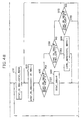
- the sync prediction/error detection unit 55 stores a program embodying an algorithm which will be explained with reference to Figure 4 and executes the algorithm under the control of the controller 35.
- the controller 35 controls an identification signal generator 37 according to the execution result of the sync prediction/error detection unit 55.
- the identification signal generator 37 receives a demodulated digital reproduction signal from the sync detector 33, and outputs the identification data ID and the data DATA.
- the apparatus of Figure 3 detects the error-sync and sync missing for each track, and adaptively determines the sync detection reference number N and the error-sync allowable number M which are used as references for sync detection of the following track, particularly, the just following track.
- step 410 the controller 35 controls the counter/store unit 53 and initializes registers (not shown) which are contained in the counter/store unit 53 and store the sync detection number CNT_N, the error-sync generation number SYNC_ERR, the sync missing number SYNC_MISS, and the identification data prediction value ID_VAL.
- the sync detection number CNT_N, the error-sync generation number SYNC_ERR, the sync missing number SYNC_MISS are initialized into zero
- the identification data prediction value ID_VAL is initialized into an initial value, for example, zero.
- the identification data prediction value ID_VAL is used to detect exactly the following identification data even when an error occurs in the identification data immediately following the sync data.
- the controller 35 initializes also the sync detection reference number N and the error-sync allowable number M stored in the reference value generator 51.
- the values of M and N are stored in the reference value generator 51 in advance for the initial operation of the system, and are newly determined for each track according to the error-sync generation number SYNC_ERR and the sync missing number SYNC_MISS.
- the sync detector 33 performs a detection operation of the sync data from the demodulated digital reproduction signal, and supplies the sync detection signal SYNC_GET representing the detection result to the sync prediction/error detection unit 55 via the controller 35.
- the controller 35 detects the identification data ID contained in the output signal of the sync detector 33 and supplies the detected identification data ID to the sync prediction/error detection unit 55.
- the sync prediction/error detection unit 55 judges whether the sync detection signal SYNC_GET is high in step 420. If the sync detection signal SYNC_GET is high, the sync prediction/error detection unit 55 executes step 430 and judges if the identification data prediction value ID_VAL stored in the counter/store unit 53 is same as that of the identification data ID output from the controller 35. It is checked whether the identification data is detected by the execution of step 430. If both values are the same in step 430, the sync prediction/error detection unit 55 executes step 440, increases the identification data prediction value ID_VAL stored in the counter/store unit 53 by one, and also increases the sync detection number CNT_N by one.
- the sync prediction/error detection unit 55 performs step 450 and increases the identification data prediction value ID_VAL stored in the counter/store unit 53 by two.
- This step 450 enables the detection of the sync data and the identification data even though the sync data is detected but the identification data is not detected due to the error.
- the sync prediction/error detection unit 55 compares the sync detection number CNT_N with the sync detection reference number N. The steps 420 through 460 are repeatedly performed until the number of detection of the sync data from the digital reproduction signal, that is, the sync detection number CNT_N is the same as the sync detection reference number N.
- step 460 If both values are the same in step 460, that is, the sync data is detected by the sync detection reference number N, the sync block term value SYNC_TERM stored in the reference value generator 51 is loaded as the block term counter value SYNC_IN_REG into the counter/store unit 53 in step 470.
- This step 470 is executed under the control of the controller 35 which controls the reference value generator 51, the counter/store unit 53 and the sync prediction/error detection unit 55.
- step 480 the counter/store unit 53 down-counts the block term counter value SYNC_IN_REG on the basis of the system clock.
- the block term counter value SYNC_IN_REG has a time value corresponding to the ninety bytes.
- the counter/store unit 53 down-counts the loaded block term counter value SYNC_IN_REG, and supplies the counted value to the sync detector 33 via the controller 35.
- the sync detector 33 can generate the sync signal SYNC although the demodulated signal of the demodulator 31 does not contain the sync data.
- the sync prediction/error detection unit 55 detects the error-sync number and the sync missing number on the basis of the sync term counter value SYNC_IN_REG whose value is decreased by the down-counting operation and the sync detection signal SYNC_GET of the sync detector 33. In more detail, the sync prediction/error detection unit 55 judges whether the block term counter value SYNC_IN_REG is zero and simultaneously the sync detection signal SYNC_GET is high in step 490.
- step 490 If both conditions are met in step 490, since sync data is exactly detected at the position of the sync detection predicting position of the sync block, the sync prediction/error detection unit 55 performs step 500 to set the error-sync generation number SYNC_ERR to zero, and then performs step 510. Meanwhile, if both conditions are not met in step 490, the sync prediction/error detection unit 55 performs step 550, to judge whether the block term counter value SYNC_IN_REG is zero, and simultaneously the SYNC_GET is low.
- a point of time where the block term counter value SYNC_IN_REG is zero means a sync detection prediction position.
- step 550 If both conditions are met in step 550, since sync missing occurs at the sync detection predicting position of the sync block, the sync prediction/error detection unit 55 increases the sync missing number SYNC_MISS by one in step 560. Thereafter, the sync prediction/error detection unit 55 performs step 510. Meanwhile, if both conditions are not met in step 550, the sync prediction/error detection unit 55 performs step 570 to judge whether the block term counter value SYNC_IN_REG is not zero, and simultaneously the sync detection signal SYNC_GET is high. If both conditions are not met in step 570, it means that the error-sync and the sync missing with respect to one sync block period are not detected completely.
- the sync prediction/error detection unit 55 performs again step 480 and the subsequent steps. Meanwhile, if both conditions are met, the sync prediction/error detection unit 55 judges that the error-sync is generated in the sync block and increases the error-sync generation number SYNC_ERR by one. In step 590, the sync prediction/error detection unit 55 judges whether the error-sync generation number SYNC_ERR is consistent with the error-sync allowable number M.
- the sync prediction/error detection unit 55 performs step 480 and the subsequent steps to detect the generation number of the sync missing and error-sync with respect to the sync block. Meanwhile, if the error-sync generation number SYNC_ERR is the same as the error-sync allowable number M in step 590, the sync prediction/error detection unit 55 judges that the error-sync of the allowable error-sync number M is detected from the sync block and performs step 510.
- step 510 the sync prediction/error detection unit 55 judges whether the identification data ID is detected from the corresponding sync block. If the identification data ID is not detected due to an error, the sync prediction/error detection unit 55 performs step 520 and increases a corresponding register value ID_RES in the counter/store unit 53 by one. Meanwhile, if the identification data ID is detected well, the sync prediction/error detection unit 55 performs step 530, and stores the identification data value ID_RES in the corresponding register value in the counter/store unit 53.
- the controller 35 reads a value ID_RES stored in a register by step 520 or 530 and supplies the read value to the identification signal generator 37, for a sync block from which the identification data is not detected due to an error after the sync detection position has been predicted.
- the identification signal generator 37 separates the identification data and the data DATA from the demodulated signal of the sync detector 33, and outputs the separated data.
- the identification signal generator 37 outputs the identification data supplied from the controller 35 as the corresponding identification data in the case of the sync block from which the identification data is not detected.
- the sync prediction/error detection unit 55 performs step 470 and the subsequent steps with respect to the following sync block. Meanwhile, if both numbers are consistent, the sync prediction/error detection unit 55 stops the detection of the channel reproduction characteristic with respect to the track.
- the sync prediction/error detection unit 55 transmits the sync missing number SYNC_MISS and the error-sync generation number SYNC_ERR obtained by such a signal processing to the reference value generator 51.
- the reference value generator 51 uses the following equations (1) through (3), to determine the error-sync allowable number M and the sync detection reference number N for a track following the track T-1 which is used to detect the sync missing number SYNC_MISS and the error-sync generation number SYNC_ERR, that is, the track T.
- [ ] is a function for determining the smallest integer value corresponding to an input.
- W G is a weight value for appropriately adjusting a degree of change of values of M and N.
- the error-sync allowable number M is further increased and simultaneously the sync detection reference number N is further decreased when the channel reproduction characteristic provides a relatively excellent circumstance for sync detection. Accordingly, a smaller number of the sync blocks can be used to detect the channel reproduction characteristic. Thus, this brings an additional effect which can determine the channel reproduction characteristic more swiftly. Also, when the channel reproduction characteristic provides a relatively poor circumstance for sync detection, the error-sync allowable number M is further decreased and simultaneously the sync detection reference number N is further increased. Accordingly, the sync detection can be accomplished even under poor channel reproduction characteristics.
- the reference value generator 51 calculates the sync detection reference number N and the error-sync allowable number M for the next track by using the above equations (1) through (3), and stores the calculated values therein.
- the sync detection reference number N and the error-sync allowable number M stored in the reference value generator 51 are used to recognize the sync detection and the channel reproduction characteristics with respect to the next track.
- the present invention uses the detected sync missing number and the error-sync generation number to determine (or see) the channel reproduction characteristic, and adapts the sync detection to the alteration of the channel reproduction characteristic after the channel reproduction characteristic has been recognized.
- the problems due to variable channel reproduction characteristics that is, one which does not detect accurately the sync position even with a predetermined number of the sync detection and the other which deviates the sync position due to the alteration of the channel reproduction characteristic after the sync position has been accurately detected, can be solved.
Landscapes
- Engineering & Computer Science (AREA)
- Signal Processing (AREA)
- Multimedia (AREA)
- Signal Processing For Digital Recording And Reproducing (AREA)
- Television Signal Processing For Recording (AREA)
- Synchronisation In Digital Transmission Systems (AREA)
Applications Claiming Priority (2)
| Application Number | Priority Date | Filing Date | Title |
|---|---|---|---|
| KR9507477 | 1995-03-31 | ||
| KR1019950007477A KR0148181B1 (ko) | 1995-03-31 | 1995-03-31 | 디지탈 기록재생시스템의 가변적 동기패턴검출장치 및 방법 |
Publications (3)
| Publication Number | Publication Date |
|---|---|
| EP0735535A2 true EP0735535A2 (de) | 1996-10-02 |
| EP0735535A3 EP0735535A3 (de) | 1997-08-13 |
| EP0735535B1 EP0735535B1 (de) | 2001-03-07 |
Family
ID=19411263
Family Applications (1)
| Application Number | Title | Priority Date | Filing Date |
|---|---|---|---|
| EP96302249A Expired - Lifetime EP0735535B1 (de) | 1995-03-31 | 1996-03-29 | Adaptives Verfahren zum Schutz von Synchronisationsblöcken in digitalen Wiedergabesystemen und Gerät dafür |
Country Status (6)
| Country | Link |
|---|---|
| US (1) | US5848218A (de) |
| EP (1) | EP0735535B1 (de) |
| JP (1) | JP2937853B2 (de) |
| KR (1) | KR0148181B1 (de) |
| CN (1) | CN1077318C (de) |
| DE (1) | DE69611945T2 (de) |
Families Citing this family (3)
| Publication number | Priority date | Publication date | Assignee | Title |
|---|---|---|---|---|
| US6245064B1 (en) | 1997-07-08 | 2001-06-12 | Atrionix, Inc. | Circumferential ablation device assembly |
| JP5765706B2 (ja) | 2011-04-28 | 2015-08-19 | サンデンホールディングス株式会社 | 電磁連結装置 |
| KR102333724B1 (ko) | 2015-10-23 | 2021-12-01 | 삼성전자주식회사 | 디스플레이 장치 및 그 제어 방법 |
Family Cites Families (10)
| Publication number | Priority date | Publication date | Assignee | Title |
|---|---|---|---|---|
| JPS5580867A (en) * | 1978-12-12 | 1980-06-18 | Sony Corp | Block synchronous signal extracting circuit |
| US4453260A (en) * | 1982-06-15 | 1984-06-05 | Tokyo Shibaura Denki Kabushiki Kaisha | Synchronizing circuit for detecting and interpolating sync signals contained in digital signal |
| US4791622A (en) * | 1983-09-19 | 1988-12-13 | Storage Technology Partners 11 | Optical data format employing resynchronizable data sectors |
| DE3642636A1 (de) * | 1986-12-13 | 1988-06-23 | Bosch Gmbh Robert | Verfahren zur erfassung und substitution von synchronworten in pcm-daten und schaltungsanordnung hierfuer |
| US5021897A (en) * | 1987-06-12 | 1991-06-04 | Matsushita Electric Industrial Co., Ltd. | Memory system for recording and reproducing block unit data |
| JP2998161B2 (ja) * | 1990-01-17 | 2000-01-11 | 富士通株式会社 | 記録媒体の同期信号読取方法及び装置 |
| JP2900507B2 (ja) * | 1990-04-26 | 1999-06-02 | ソニー株式会社 | デジタルデータ再生装置 |
| DE69122338T2 (de) * | 1990-08-03 | 1997-02-13 | Canon Kk | Synchronsignal-Detektorschaltung und dieselbe enthaltender Synchronsignal-Detektorapparat |
| JP3306938B2 (ja) * | 1992-11-25 | 2002-07-24 | ソニー株式会社 | 同期符号抽出回路 |
| US5363360A (en) * | 1993-09-27 | 1994-11-08 | Eastman Kodak Company | Method and apparatus for detecting and processing synchronization marks extracted from a prerecorded wobbled groove on a compact disk |
-
1995
- 1995-03-31 KR KR1019950007477A patent/KR0148181B1/ko not_active Expired - Fee Related
-
1996
- 1996-03-29 US US08/624,928 patent/US5848218A/en not_active Expired - Fee Related
- 1996-03-29 DE DE69611945T patent/DE69611945T2/de not_active Expired - Fee Related
- 1996-03-29 JP JP8076596A patent/JP2937853B2/ja not_active Expired - Fee Related
- 1996-03-29 EP EP96302249A patent/EP0735535B1/de not_active Expired - Lifetime
- 1996-03-31 CN CN96107260A patent/CN1077318C/zh not_active Expired - Fee Related
Also Published As
| Publication number | Publication date |
|---|---|
| KR960035580A (ko) | 1996-10-24 |
| EP0735535B1 (de) | 2001-03-07 |
| US5848218A (en) | 1998-12-08 |
| DE69611945T2 (de) | 2001-06-21 |
| DE69611945D1 (de) | 2001-04-12 |
| JPH08339640A (ja) | 1996-12-24 |
| JP2937853B2 (ja) | 1999-08-23 |
| CN1144957A (zh) | 1997-03-12 |
| CN1077318C (zh) | 2002-01-02 |
| EP0735535A3 (de) | 1997-08-13 |
| KR0148181B1 (ko) | 1998-10-15 |
Similar Documents
| Publication | Publication Date | Title |
|---|---|---|
| US6175683B1 (en) | Digital signal recording and reproduction apparatus suitable for recording and reproducing a compressed video signal | |
| US6301065B1 (en) | Method for recording and reproducing CRT various types of data so as to permit the use of the same mechanical and servo systems thereof | |
| US5930448A (en) | Tracking control circuit and method in digital image recording and reproducing device using bit error rate | |
| US5854876A (en) | Circuit and method for sync detection and protection | |
| EP0735535B1 (de) | Adaptives Verfahren zum Schutz von Synchronisationsblöcken in digitalen Wiedergabesystemen und Gerät dafür | |
| EP0376217B1 (de) | Gerät zur Aufzeichnung und Wiedergabe von Daten | |
| US5182680A (en) | Recording control system | |
| JP3702015B2 (ja) | フレーム番号修正装置及び方法 | |
| JPH0760571B2 (ja) | デイスク再生装置のアドレスデ−タ処理方式 | |
| US6014492A (en) | Video signal recording and reproducing apparatus for digital video cassette tape recorder | |
| US6209117B1 (en) | Method for canceling abnormal synchronization signal | |
| US5937135A (en) | Tape-independent video signal recording and reproducing apparatus | |
| US5995307A (en) | Method of forcibly judging a sector synchronous signal for a disk reproducing apparatus | |
| US5870365A (en) | Start ID recording system for use in a digital audio information recording apparatus | |
| JP3455043B2 (ja) | 信号再生装置 | |
| JPH10134515A (ja) | 同期回路 | |
| KR100240601B1 (ko) | 디지털 비디오 홈 시스템형 비디오 카세트 레코더에서의 트랙 넘버 결정 방법 및 장치 | |
| KR100269164B1 (ko) | 동기신호패널검출방법 | |
| JP3271073B2 (ja) | 磁気再生装置 | |
| JP2997323B2 (ja) | 追記形光ディスクの記録方法 | |
| KR100188662B1 (ko) | 디지탈 비디오 테이프 레코더의 오디오 에러 정정 장치 | |
| JP2959320B2 (ja) | Id符号検出方法及びid符号検出装置 | |
| KR100584532B1 (ko) | 디지털 비디오 캠코더의 서보 제어장치 및 그 방법 | |
| KR100252109B1 (ko) | 디지털 브이씨알의 기록전류 자동설정 방법 및 장치 | |
| EP1441519A1 (de) | Drehkopftrommelgeschwindigkeitssteueranlage für Standard-Auflösung-Fernsehkassettenaufnahmegerät |
Legal Events
| Date | Code | Title | Description |
|---|---|---|---|
| PUAI | Public reference made under article 153(3) epc to a published international application that has entered the european phase |
Free format text: ORIGINAL CODE: 0009012 |
|
| 17P | Request for examination filed |
Effective date: 19960424 |
|
| AK | Designated contracting states |
Kind code of ref document: A2 Designated state(s): DE FR GB |
|
| PUAL | Search report despatched |
Free format text: ORIGINAL CODE: 0009013 |
|
| AK | Designated contracting states |
Kind code of ref document: A3 Designated state(s): DE FR GB |
|
| 17Q | First examination report despatched |
Effective date: 19980903 |
|
| GRAG | Despatch of communication of intention to grant |
Free format text: ORIGINAL CODE: EPIDOS AGRA |
|
| 17Q | First examination report despatched |
Effective date: 19980903 |
|
| GRAG | Despatch of communication of intention to grant |
Free format text: ORIGINAL CODE: EPIDOS AGRA |
|
| GRAH | Despatch of communication of intention to grant a patent |
Free format text: ORIGINAL CODE: EPIDOS IGRA |
|
| GRAH | Despatch of communication of intention to grant a patent |
Free format text: ORIGINAL CODE: EPIDOS IGRA |
|
| GRAA | (expected) grant |
Free format text: ORIGINAL CODE: 0009210 |
|
| AK | Designated contracting states |
Kind code of ref document: B1 Designated state(s): DE FR GB |
|
| REF | Corresponds to: |
Ref document number: 69611945 Country of ref document: DE Date of ref document: 20010412 |
|
| ET | Fr: translation filed | ||
| REG | Reference to a national code |
Ref country code: GB Ref legal event code: IF02 |
|
| PLBE | No opposition filed within time limit |
Free format text: ORIGINAL CODE: 0009261 |
|
| STAA | Information on the status of an ep patent application or granted ep patent |
Free format text: STATUS: NO OPPOSITION FILED WITHIN TIME LIMIT |
|
| 26N | No opposition filed | ||
| PGFP | Annual fee paid to national office [announced via postgrant information from national office to epo] |
Ref country code: FR Payment date: 20080311 Year of fee payment: 13 Ref country code: DE Payment date: 20080407 Year of fee payment: 13 |
|
| PGFP | Annual fee paid to national office [announced via postgrant information from national office to epo] |
Ref country code: GB Payment date: 20080402 Year of fee payment: 13 |
|
| GBPC | Gb: european patent ceased through non-payment of renewal fee |
Effective date: 20090329 |
|
| REG | Reference to a national code |
Ref country code: FR Ref legal event code: ST Effective date: 20091130 |
|
| PG25 | Lapsed in a contracting state [announced via postgrant information from national office to epo] |
Ref country code: DE Free format text: LAPSE BECAUSE OF NON-PAYMENT OF DUE FEES Effective date: 20091001 |
|
| PG25 | Lapsed in a contracting state [announced via postgrant information from national office to epo] |
Ref country code: GB Free format text: LAPSE BECAUSE OF NON-PAYMENT OF DUE FEES Effective date: 20090329 Ref country code: FR Free format text: LAPSE BECAUSE OF NON-PAYMENT OF DUE FEES Effective date: 20091123 |