EP0736351A1 - Fraise spirale 2 tailles et méthode pour sa fabrication - Google Patents
Fraise spirale 2 tailles et méthode pour sa fabrication Download PDFInfo
- Publication number
- EP0736351A1 EP0736351A1 EP96105359A EP96105359A EP0736351A1 EP 0736351 A1 EP0736351 A1 EP 0736351A1 EP 96105359 A EP96105359 A EP 96105359A EP 96105359 A EP96105359 A EP 96105359A EP 0736351 A1 EP0736351 A1 EP 0736351A1
- Authority
- EP
- European Patent Office
- Prior art keywords
- negative relief
- relief face
- width
- end mill
- circular land
- Prior art date
- Legal status (The legal status is an assumption and is not a legal conclusion. Google has not performed a legal analysis and makes no representation as to the accuracy of the status listed.)
- Granted
Links
Images




Classifications
-
- B—PERFORMING OPERATIONS; TRANSPORTING
- B23—MACHINE TOOLS; METAL-WORKING NOT OTHERWISE PROVIDED FOR
- B23C—MILLING
- B23C5/00—Milling-cutters
- B23C5/02—Milling-cutters characterised by the shape of the cutter
- B23C5/10—Shank-type cutters, i.e. with an integral shaft
- B23C5/1081—Shank-type cutters, i.e. with an integral shaft with permanently fixed cutting inserts
-
- B—PERFORMING OPERATIONS; TRANSPORTING
- B23—MACHINE TOOLS; METAL-WORKING NOT OTHERWISE PROVIDED FOR
- B23C—MILLING
- B23C2210/00—Details of milling cutters
- B23C2210/20—Number of cutting edges
- B23C2210/203—Number of cutting edges four
-
- B—PERFORMING OPERATIONS; TRANSPORTING
- B23—MACHINE TOOLS; METAL-WORKING NOT OTHERWISE PROVIDED FOR
- B23C—MILLING
- B23C2210/00—Details of milling cutters
- B23C2210/32—Details of teeth
- B23C2210/321—Lands, i.e. the area on the rake face in the immediate vicinity of the cutting edge
-
- Y—GENERAL TAGGING OF NEW TECHNOLOGICAL DEVELOPMENTS; GENERAL TAGGING OF CROSS-SECTIONAL TECHNOLOGIES SPANNING OVER SEVERAL SECTIONS OF THE IPC; TECHNICAL SUBJECTS COVERED BY FORMER USPC CROSS-REFERENCE ART COLLECTIONS [XRACs] AND DIGESTS
- Y10—TECHNICAL SUBJECTS COVERED BY FORMER USPC
- Y10T—TECHNICAL SUBJECTS COVERED BY FORMER US CLASSIFICATION
- Y10T407/00—Cutters, for shaping
- Y10T407/19—Rotary cutting tool
- Y10T407/1946—Face or end mill
- Y10T407/1948—Face or end mill with cutting edge entirely across end of tool [e.g., router bit, end mill, etc.]
-
- Y—GENERAL TAGGING OF NEW TECHNOLOGICAL DEVELOPMENTS; GENERAL TAGGING OF CROSS-SECTIONAL TECHNOLOGIES SPANNING OVER SEVERAL SECTIONS OF THE IPC; TECHNICAL SUBJECTS COVERED BY FORMER USPC CROSS-REFERENCE ART COLLECTIONS [XRACs] AND DIGESTS
- Y10—TECHNICAL SUBJECTS COVERED BY FORMER USPC
- Y10T—TECHNICAL SUBJECTS COVERED BY FORMER US CLASSIFICATION
- Y10T407/00—Cutters, for shaping
- Y10T407/19—Rotary cutting tool
- Y10T407/1952—Having peripherally spaced teeth
- Y10T407/1962—Specified tooth shape or spacing
- Y10T407/1964—Arcuate cutting edge
- Y10T407/1966—Helical tooth
-
- Y—GENERAL TAGGING OF NEW TECHNOLOGICAL DEVELOPMENTS; GENERAL TAGGING OF CROSS-SECTIONAL TECHNOLOGIES SPANNING OVER SEVERAL SECTIONS OF THE IPC; TECHNICAL SUBJECTS COVERED BY FORMER USPC CROSS-REFERENCE ART COLLECTIONS [XRACs] AND DIGESTS
- Y10—TECHNICAL SUBJECTS COVERED BY FORMER USPC
- Y10T—TECHNICAL SUBJECTS COVERED BY FORMER US CLASSIFICATION
- Y10T407/00—Cutters, for shaping
- Y10T407/26—Cutters, for shaping comprising cutting edge bonded to tool shank
Definitions
- the present invention relates to a spiral end mill and a method of manufacturing the same, and more specifically, it relates to a spiral end mill comprising a hard sintered compact which is arranged on its insert portion and a negative relief face having a chamfer for reducing the angle of an axial rake which is provided on the forward end of the insert portion, and a method of manufacturing the same.
- a material is so insufficient in wear resistance that it is difficult to maintain stable working accuracy over a long time.
- a tool corner portion is extremely worn in the conventional tool material to consequently reduce the tool life when the radius (R) of the corner portion is defined to be not more than 0.2 mm, for example. Therefore, employment of a spiral end mill having an insert portion made of a hard sintered compact which is excellent in wear resistance is proposed.
- a spiral end mill having an insert portion made of a hard sintered compact which is less tougher than with the conventional material is set at a high helix angle of 15 to 45°, for example, the front edge is easily chipped.
- a negative relief face having a chamfer of at least 0.1 mm in width, for example, for reducing the helix angle by approximating an axial rake to 0°, for example. The width and angle of the negative relief face are set in response to the cutting conditions etc.
- a circular land 3 may be provided to cover a negative relief face 6, as shown in Fig. 11.
- a hard sintered compact 1 forming an insert portion is bonded to a surface of a tool body 2.
- Fig. 11 is a schematic diagram as viewed from the side of a peripheral flank 4.
- the circular land 3 must have a width h of at least Wtan ⁇ mm, assuming that W represents the width of the negative relief face 6 and ⁇ represents the helix angle.
- W represents the width of the negative relief face 6
- ⁇ represents the helix angle.
- the front edge may be chipped as hereinabove described.
- An object of the present invention is to provide a spiral end mill which can approximate the shape of a corner of a work surface to that of a sharp corner while attaining excellent cutting performance.
- Another object of the present invention is to provide a method of manufacturing a spiral end mill which can readily form a spiral end mill capable of approximating the shape of a corner of a work surface to that of a sharp corner.
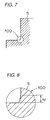
- the present invention notes the following point: With increase in difficulty in cutting of workpieces and sophistication of application, a spiral end mill which is made of a hard material mainly composed of diamond or CBN is strongly required. Particularly with sophistication of application, tool accuracy allowing no small steps shown in Figs. 7 and 8 is required in recent years. In particular, it has recently been proved that even an extremely small step exerts a remarkable influence on the performance of the product in a mold or a fluid carrier to which accuracy is required. Thus, the present invention has been proposed in order to solve the problems.
- a spiral end mill comprises a hard sintered compact which is arranged on its insert portion and a negative relief face having a chamfer for reducing the angle of an axial rake which is provided on the front end of the insert portion.
- This spiral end mill comprises first and second circular land portions.
- the first circular land portion is provided to have a substantially constant first width along an outer peripheral portion of the insert portion excluding the negative relief face.
- the second round portion has a substantially constant second width, and is provided on the outer peripheral portion of the negative relief face of the insert portion to be continuous with the first circular land portion so that a helix angle of a line which is defined by the second circular land portion and a peripheral flank is smaller than that of the first circular land portion.
- the width (W) of the negative relief face may be set in the range of at least 0.05 mm and not more than 0.5 mm.
- the second circular land portion defining a line having a helix angle which is smaller than that of the first circular land portion with the peripheral flank is formed on the outer peripheral portion of the negative relief face of the insert portion to be continuous with the first round portion which is provided along the outer peripheral portion of the insert portion excluding the negative relief face, whereby the negative relief face is prevented from reduction of the tool diameter.
- a corner of a work surface is finished in a shape which is close to that of a sharp corner.
- a method of manufacturing a spiral end mill comprises the step of changing the widths of circular lands which are formed on an outer peripheral portion of an insert portion excluding a negative relief face and that of the negative relief face at the time of working a relief angle on the outer periphery of the insert portion by changing helix angles between the outer peripheral portion of the insert portion excluding the negative relief face and that of the negative relief face.
- the width (W) of the negative relief face may be set in the range of at least 0.05 mm and not more than 0.5 mm.
- the widths of the circular lands which are formed on the outer peripheral portion of the insert portion excluding the negative relief face and that of the negative relief face are changed at the time of working a relief angle on the outer periphery of the insert portion by changing the helix angles between the outer peripheral portion of the insert portion excluding the negative relief face and that of the negative relief face, whereby the circular land portions of the outer peripheral portion excluding the negative relief face and that of the negative relief face are readily formed with different widths.
- the work surface can be more excellently finished when the width (W) of the negative relief face is set in the range of at least 0.05 mm and not more than 0.5 mm.
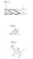
- a hard sintered compact 1 is bonded to an insert portion of a tool body 2.
- a spiral end mill having such an insert portion of the hard sintered compact 1 is set at a high helix angle ⁇ (see Fig. 11) of 15 to 45°, for example, the forefront wedge angle ⁇ is reduced and the edge angle is sharpened, as shown in Fig. 3.
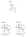
- a negative relief face 6 which is chamfered for setting or approximating an axial rake at or to 0°, for example, is generally provided on the forefront portion as shown in Fig. 4, in order to prevent the forefront edge from chipping.
- a circular land 3b having a width H which is larger than a width h of a circular land 3a provided on an outer peripheral portion of an insert portion consisting of a hard sintered compact 1 is provided on a negative relief face 6 to be continuous with the circular land 3a according to the present invention, as shown in each of Figs. 5A and 5B. Due to such provision of the circular land 3b which is obtained by changing the width h of the circular land 3a provided on the outer peripheral portion to the width H on the negative relief face 6, the circular lands 3a and 3b remain on the overall region of the insert portion.
- the width h of the circular land 3a is preferably not more than 0.15 mm and at least 0.01 mm. If the width h exceeds 0.15 mm, the cutting resistance is increased and the cutting face is waved to cause extreme difficulty in manufacturing of the tool. More preferably, the width h of the circular land 3a is not more than 0.1 mm, in order to reduce the cutting resistance.
- the circular lands 3a and 3b according to the present invention may be shaped as shown in Figs. 14A and 14B, in place of the shapes shown in Figs. 5A and 5B.
- the peripheral cutting edge was formed in a sharp corner, with no provision of a negative relief face, on the forward end.
- sharp corner indicates a cutting edge which is formed by driving a flank into the cutting edge and rounding up the same while leaving no negative relief face in working.
- the peripheral cutting edge was formed in a sharp corner, while providing the negative relief face 6 on the forward end by a width W of 0.2 mm.
- the negative relief face 6 was provided on the forward end by a width W of 0.2 mm, while the circular lands 3a and 3b having widths h and H of 0.02 mm and 0.1 mm were provided on the peripheral cutting edge portion and the outer periphery of the negative relief face 6 respectively.
- the negative relief face 6 was provided on the forward end by a width W of 0.2 mm, while the circular lands 3a and 3b having widths h and H of 0.02 mm were provided on the peripheral cutting edge portion and the outer periphery of the negative relief face 6 respectively.
- a negative relief face 6 was provided on a forward end by a width W of 0.2 mm, and a circular land 3 having a width h of 0.3 mm was provided on a peripheral cutting edge portion. Namely, the width h of the circular land 3 was increased for covering the negative relief face 6 with the circular land 3, thereby suppressing reduction of the tool diameter.
- a negative relief face 6 was provided on a forward end by a width W of 0.2 mm, and a circular land 3 having a width h of 0.3 mm was provided on a peripheral cutting edge portion.
- the circular land 3 was broken on the negative relief face 6 due to the conventional working method.
- the forward end of the insert was chipped with a cutting distance of 1 to 2 m.
- the comparative tool shown in Fig. 11 became unusable in an initial stage due to large side slanting degree and slanting degree.
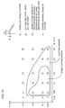
- Samples of the tool shown in Fig. 5A were prepared to study the widths H and W of the circular land 3b and the negative relief face 6.
- the samples of the tool shown in Fig. 5A were employed to work workpieces of an aluminum alloy containing 20 percent by weight of Si, and subjected to evaluation of cutting states and states of finished surfaces under conditions similar to those of Example 1, except that the widths H of the circular lands 3b were (1) 0.02 mm, (2) 0.1 mm, (3) 0.3 mm and (4) 0.5 mm while the widths W of the negative relief faces 6 were (1) 0.03 mm, (2) 0.05 mm, (3) 0.1 mm, (4) 0.2 mm, (5) 0.4 mm and (6) 0.5 mm.
- Fig. 13 shows the results of the cutting test with the aforementioned parameters.
- the tool is capable of cutting when the width H of the circular land 3b is not more than 0. 3 mm, and cutting resistance is reduced as the width H is reduced.
- the width H of the circular land 3b is preferably set in the range of at least 0.01 mm and not more than 0.3 mm. If the width H exceeds 0.3 mm, a chatter is caused and the cutting noise is increased, while the circular land 3b is deposited to deteriorate the state of the work surface. If the width H is less than 0.01 mm, on the other hand, control is unpractically made difficult on the technique of manufacturing the tool. Therefore, the width H of the circular land 3b is preferably at least 0.01 mm and not more than 0.3 mm.
- the tool is capable of cutting when the width W is at least 0.05 mm and not more than 0.5 mm, and this width W is preferably not more than 0.4 mm, as shown in Fig. 13. Further, the width W is preferably increased in consideration of the cutting edge strength if stable cutting is attained, and preferably at least 0.1 mm in general. In consideration of the aforementioned points, the width W of the negative relief face 6 is preferably set in the range of at least 0.05 mm and not more than 0.5 mm. Initial chipping is easily caused in cutting if the width W is less than 0.05 mm, while the cutting noise is disadvantageously increased if the width W exceeds 0.5 mm. In the spiral end mill according to the present invention, the width W is more preferably set in the range of at least 0.1 mm and not more than 0.4 mm.
- the corner of the work surface can be finished in a shape which is close to that of a sharp corner by providing the first and second circular lands on the overall region of the insert portion from the outer periphery to the negative relief face, even if the negative relief face is provided on the forward end of the insert portion.
- the hard sintered compact which is excellent in wear resistance is employed as the insert portion, whereby shape accuracy of the corner portion can be stably ensured over a long time as compared with the conventional end mill consisting of cemented carbide or high-speed steel.
- the circular lands can be provided on the outer peripheral portion of the insert portion excluding the negative relief face and that of the negative relief face at the time of working a relief angle in the outer periphery of the insert portion by changing the helix angles between the outer peripheral portion excluding the negative relief face and that of the negative relief face. Consequently, it is possible to readily form a spiral end mill which can approximate the shape of a corner of a work surface to that of a sharp corner.
Landscapes
- Engineering & Computer Science (AREA)
- Mechanical Engineering (AREA)
- Milling Processes (AREA)
Applications Claiming Priority (3)
| Application Number | Priority Date | Filing Date | Title |
|---|---|---|---|
| JP8104695 | 1995-04-06 | ||
| JP08104695A JP3352279B2 (ja) | 1995-04-06 | 1995-04-06 | スパイラルエンドミルおよびその製造方法 |
| JP81046/95 | 1995-04-06 |
Publications (2)
| Publication Number | Publication Date |
|---|---|
| EP0736351A1 true EP0736351A1 (fr) | 1996-10-09 |
| EP0736351B1 EP0736351B1 (fr) | 2001-07-25 |
Family
ID=13735490
Family Applications (1)
| Application Number | Title | Priority Date | Filing Date |
|---|---|---|---|
| EP96105359A Expired - Lifetime EP0736351B1 (fr) | 1995-04-06 | 1996-04-03 | Fraise spirale 2 tailles et méthode pour sa fabrication |
Country Status (4)
| Country | Link |
|---|---|
| US (1) | US5725333A (fr) |
| EP (1) | EP0736351B1 (fr) |
| JP (1) | JP3352279B2 (fr) |
| DE (1) | DE69614021T2 (fr) |
Cited By (1)
| Publication number | Priority date | Publication date | Assignee | Title |
|---|---|---|---|---|
| EP3507044B1 (fr) | 2016-08-31 | 2020-09-30 | Datron AG | Outil de fraisage à un seul tranchant |
Families Citing this family (18)
| Publication number | Priority date | Publication date | Assignee | Title |
|---|---|---|---|---|
| JP2001300813A (ja) * | 2000-02-18 | 2001-10-30 | Sumitomo Electric Ind Ltd | ボールエンドミル |
| JP2001293611A (ja) * | 2000-04-17 | 2001-10-23 | Nachi Fujikoshi Corp | 超硬エンドミル |
| KR100421148B1 (ko) * | 2001-04-02 | 2004-03-10 | 강호연 | 비철금속 강력절삭용 엔드밀 |
| KR100431921B1 (ko) * | 2001-04-02 | 2004-05-22 | 강호연 | 고속 가공용 엔드밀 |
| US6846135B2 (en) * | 2002-03-25 | 2005-01-25 | Hitachi Tool Engineering Ltd. | Radius end mill having radius edge enhanced in resistance to chipping and fracture |
| JP4088570B2 (ja) * | 2003-05-08 | 2008-05-21 | 松下電器産業株式会社 | 非回転切削工具 |
| US7293945B2 (en) * | 2003-05-08 | 2007-11-13 | Matsushita Electric Industrial Co., Ltd | Non-rotary cutting tool and process of machining scroll member by using the same |
| JP2006015417A (ja) * | 2004-06-30 | 2006-01-19 | Mitsubishi Materials Kobe Tools Corp | エンドミル |
| US20060160638A1 (en) * | 2005-01-14 | 2006-07-20 | Mccabe Terrill R | Golf club with uniform face thickness |
| JP4831568B2 (ja) * | 2005-01-28 | 2011-12-07 | 株式会社不二越 | エンドミル、加工装置、切削方法及び、加工物 |
| US9468980B2 (en) | 2007-04-03 | 2016-10-18 | H. Sam Cho | Contoured PCD and PCBN segments for cutting tools containing such segments |
| US8052765B2 (en) | 2007-04-03 | 2011-11-08 | Cho H Sam | Contoured PCD and PCBN for twist drill tips and end mills and methods of forming the same |
| USD627806S1 (en) * | 2009-06-11 | 2010-11-23 | Iscar, Ltd | Helical flute end mill |
| IL202196A (en) * | 2009-11-17 | 2015-03-31 | Kennametal Inc | Optimizing the geometric cutting edge in spherical nibs |
| US9682434B2 (en) | 2011-09-26 | 2017-06-20 | Kennametal Inc. | Milling cutter for cutting a ninety-degree shoulder in a workpiece |
| JP6038354B2 (ja) * | 2014-01-07 | 2016-12-07 | 三菱電機株式会社 | エンドミル |
| US10112200B2 (en) * | 2015-04-29 | 2018-10-30 | Spokane Industries | Composite milling component |
| US11926005B2 (en) * | 2017-08-03 | 2024-03-12 | Vestas Wind Systems A/S | Mill bit for the manufacture of a wind turbine blade and method of forming same |
Citations (5)
| Publication number | Priority date | Publication date | Assignee | Title |
|---|---|---|---|---|
| GB932572A (en) * | 1960-12-07 | 1963-07-31 | Birmingham Tool & Gauge Compan | Improvements relating to end-mills |
| DD265097A1 (de) * | 1987-09-30 | 1989-02-22 | Werkzeugind Forschzent | Walzenstirnfraeser mit schraubenlinienfoermig verlaufenden umfangsschneidkanten |
| US5226760A (en) * | 1990-02-07 | 1993-07-13 | Gn Tool Co., Ltd. | Cutting tool with twisted edge and manufacturing method thereof |
| WO1994008745A1 (fr) * | 1992-10-15 | 1994-04-28 | Sandvik Ab | Fraise a deux tailles a axe vertical possedant une ame de materiaux composes et un revetement en materiau dur |
| EP0695596A1 (fr) * | 1994-07-06 | 1996-02-07 | Sumitomo Electric Industries, Ltd. | Outil de coupe rotatif et sa méthode de fabrication |
Family Cites Families (8)
| Publication number | Priority date | Publication date | Assignee | Title |
|---|---|---|---|---|
| JPS5946615U (ja) * | 1982-09-20 | 1984-03-28 | 株式会社不二越 | エンドミル |
| JPS59175915A (ja) * | 1983-03-24 | 1984-10-05 | Kawasaki Heavy Ind Ltd | エンドミル |
| JPS604316U (ja) * | 1983-06-22 | 1985-01-12 | 東芝タンガロイ株式会社 | ろう付け式のエンドミル |
| JP2556393B2 (ja) * | 1990-02-07 | 1996-11-20 | ジーエヌツール株式会社 | ねじれ刃を有する切削工具及びその製造方法 |
| US5049009A (en) * | 1990-08-21 | 1991-09-17 | The Weldon Tool Company | Improved cutting tool |
| JP2502539Y2 (ja) * | 1990-09-21 | 1996-06-26 | 三菱マテリアル株式会社 | エンドミル |
| JPH08141820A (ja) * | 1994-11-11 | 1996-06-04 | Nec Corp | エンドミル |
| JP6232043B2 (ja) | 2012-03-19 | 2017-11-15 | コーニンクレッカ フィリップス エヌ ヴェKoninklijke Philips N.V. | K空間領域の中央および周辺のサンプリング最中での呼吸運動の検出を用いた磁気共鳴画像の再構成 |
-
1995
- 1995-04-06 JP JP08104695A patent/JP3352279B2/ja not_active Expired - Fee Related
-
1996
- 1996-04-02 US US08/626,476 patent/US5725333A/en not_active Expired - Fee Related
- 1996-04-03 EP EP96105359A patent/EP0736351B1/fr not_active Expired - Lifetime
- 1996-04-03 DE DE69614021T patent/DE69614021T2/de not_active Expired - Fee Related
Patent Citations (5)
| Publication number | Priority date | Publication date | Assignee | Title |
|---|---|---|---|---|
| GB932572A (en) * | 1960-12-07 | 1963-07-31 | Birmingham Tool & Gauge Compan | Improvements relating to end-mills |
| DD265097A1 (de) * | 1987-09-30 | 1989-02-22 | Werkzeugind Forschzent | Walzenstirnfraeser mit schraubenlinienfoermig verlaufenden umfangsschneidkanten |
| US5226760A (en) * | 1990-02-07 | 1993-07-13 | Gn Tool Co., Ltd. | Cutting tool with twisted edge and manufacturing method thereof |
| WO1994008745A1 (fr) * | 1992-10-15 | 1994-04-28 | Sandvik Ab | Fraise a deux tailles a axe vertical possedant une ame de materiaux composes et un revetement en materiau dur |
| EP0695596A1 (fr) * | 1994-07-06 | 1996-02-07 | Sumitomo Electric Industries, Ltd. | Outil de coupe rotatif et sa méthode de fabrication |
Cited By (1)
| Publication number | Priority date | Publication date | Assignee | Title |
|---|---|---|---|---|
| EP3507044B1 (fr) | 2016-08-31 | 2020-09-30 | Datron AG | Outil de fraisage à un seul tranchant |
Also Published As
| Publication number | Publication date |
|---|---|
| DE69614021T2 (de) | 2002-06-06 |
| DE69614021D1 (de) | 2001-08-30 |
| EP0736351B1 (fr) | 2001-07-25 |
| JP3352279B2 (ja) | 2002-12-03 |
| US5725333A (en) | 1998-03-10 |
| JPH08276311A (ja) | 1996-10-22 |
Similar Documents
| Publication | Publication Date | Title |
|---|---|---|
| EP0736351B1 (fr) | Fraise spirale 2 tailles et méthode pour sa fabrication | |
| US4335984A (en) | Metalcutting insert for roughing and finishing | |
| US5123217A (en) | Drill for use in drilling hard and brittle materials | |
| EP0559961B1 (fr) | Fraise à queue à haute rigidité | |
| EP1807233A1 (fr) | Fraise en bout a cannelures helicoidales, presentant une arete coupante comportant plusieurs parties | |
| JP2007030074A (ja) | ラジアスエンドミル及び切削加工方法 | |
| US5022797A (en) | Diamond tool | |
| EP1559493A2 (fr) | Fraise sphérique à queue | |
| JPS625726B2 (fr) | ||
| KR960007687Y1 (ko) | 엔드밀 | |
| US5190420A (en) | Solid end mill for finishing the face or side of hard work | |
| EP0404298B1 (fr) | Fraise à queue pour le finissage de pièces d'oeuvre dures | |
| JPH07299634A (ja) | エンドミル | |
| JPH08112710A (ja) | エンドミル | |
| JP3036343B2 (ja) | エンドミル | |
| JP2985494B2 (ja) | 穴明け工具 | |
| JPS6246491Y2 (fr) | ||
| JPH03161280A (ja) | 硬脆材穴加工用工具 | |
| JPH04289012A (ja) | エンドミル | |
| JP2021088008A (ja) | 高硬度切削工具 | |
| JPH04102715U (ja) | エンドミル | |
| JPH05293709A (ja) | ドリル | |
| JPS6147645B2 (fr) | ||
| JPH0790410B2 (ja) | スモールリリーフ付き切削工具 | |
| JP4136139B2 (ja) | エンドミル |
Legal Events
| Date | Code | Title | Description |
|---|---|---|---|
| PUAI | Public reference made under article 153(3) epc to a published international application that has entered the european phase |
Free format text: ORIGINAL CODE: 0009012 |
|
| AK | Designated contracting states |
Kind code of ref document: A1 Designated state(s): DE FR GB |
|
| 17P | Request for examination filed |
Effective date: 19961021 |
|
| 17Q | First examination report despatched |
Effective date: 19990208 |
|
| GRAG | Despatch of communication of intention to grant |
Free format text: ORIGINAL CODE: EPIDOS AGRA |
|
| GRAG | Despatch of communication of intention to grant |
Free format text: ORIGINAL CODE: EPIDOS AGRA |
|
| GRAH | Despatch of communication of intention to grant a patent |
Free format text: ORIGINAL CODE: EPIDOS IGRA |
|
| GRAH | Despatch of communication of intention to grant a patent |
Free format text: ORIGINAL CODE: EPIDOS IGRA |
|
| GRAA | (expected) grant |
Free format text: ORIGINAL CODE: 0009210 |
|
| AK | Designated contracting states |
Kind code of ref document: B1 Designated state(s): DE FR GB |
|
| REF | Corresponds to: |
Ref document number: 69614021 Country of ref document: DE Date of ref document: 20010830 |
|
| EN | Fr: translation not filed | ||
| REG | Reference to a national code |
Ref country code: GB Ref legal event code: IF02 |
|
| EN | Fr: translation not filed |
Free format text: BO 01/51 PAGES: 265, IL Y A LIEU DE SUPPRIMER: LA MENTION DE LA NON REMISE. LA REMISE EST PUBLIEE DANS LE PRESENT BOPI. |
|
| ET | Fr: translation filed | ||
| PLBE | No opposition filed within time limit |
Free format text: ORIGINAL CODE: 0009261 |
|
| STAA | Information on the status of an ep patent application or granted ep patent |
Free format text: STATUS: NO OPPOSITION FILED WITHIN TIME LIMIT |
|
| 26N | No opposition filed | ||
| PGFP | Annual fee paid to national office [announced via postgrant information from national office to epo] |
Ref country code: GB Payment date: 20070328 Year of fee payment: 12 |
|
| PGFP | Annual fee paid to national office [announced via postgrant information from national office to epo] |
Ref country code: DE Payment date: 20070329 Year of fee payment: 12 |
|
| PGFP | Annual fee paid to national office [announced via postgrant information from national office to epo] |
Ref country code: FR Payment date: 20070411 Year of fee payment: 12 |
|
| GBPC | Gb: european patent ceased through non-payment of renewal fee |
Effective date: 20080403 |
|
| PG25 | Lapsed in a contracting state [announced via postgrant information from national office to epo] |
Ref country code: DE Free format text: LAPSE BECAUSE OF NON-PAYMENT OF DUE FEES Effective date: 20081101 |
|
| REG | Reference to a national code |
Ref country code: FR Ref legal event code: ST Effective date: 20081231 |
|
| PG25 | Lapsed in a contracting state [announced via postgrant information from national office to epo] |
Ref country code: FR Free format text: LAPSE BECAUSE OF NON-PAYMENT OF DUE FEES Effective date: 20080430 |
|
| PG25 | Lapsed in a contracting state [announced via postgrant information from national office to epo] |
Ref country code: GB Free format text: LAPSE BECAUSE OF NON-PAYMENT OF DUE FEES Effective date: 20080403 |