EP0736754B1 - Dispositif pour charger un récipient avec des articles pesés - Google Patents
Dispositif pour charger un récipient avec des articles pesés Download PDFInfo
- Publication number
- EP0736754B1 EP0736754B1 EP96302275A EP96302275A EP0736754B1 EP 0736754 B1 EP0736754 B1 EP 0736754B1 EP 96302275 A EP96302275 A EP 96302275A EP 96302275 A EP96302275 A EP 96302275A EP 0736754 B1 EP0736754 B1 EP 0736754B1
- Authority
- EP
- European Patent Office
- Prior art keywords
- additive
- articles
- cups
- cup
- auxiliary
- Prior art date
- Legal status (The legal status is an assumption and is not a legal conclusion. Google has not performed a legal analysis and makes no representation as to the accuracy of the status listed.)
- Expired - Lifetime
Links
Images




Classifications
-
- G—PHYSICS
- G01—MEASURING; TESTING
- G01G—WEIGHING
- G01G13/00—Weighing apparatus with automatic feed or discharge for weighing-out batches of material
- G01G13/02—Means for automatically loading weigh pans or other receptacles, e.g. disposable containers, under control of the weighing mechanism
- G01G13/04—Means for automatically loading weigh pans or other receptacles, e.g. disposable containers, under control of the weighing mechanism involving dribble-feed means controlled by the weighing mechanism to top up the receptacle to the target weight
- G01G13/06—Means for automatically loading weigh pans or other receptacles, e.g. disposable containers, under control of the weighing mechanism involving dribble-feed means controlled by the weighing mechanism to top up the receptacle to the target weight wherein the main feed is effected by gravity from a hopper or chute
-
- G—PHYSICS
- G01—MEASURING; TESTING
- G01G—WEIGHING
- G01G19/00—Weighing apparatus or methods adapted for special purposes not provided for in the preceding groups
- G01G19/387—Weighing apparatus or methods adapted for special purposes not provided for in the preceding groups for combinatorial weighing, i.e. selecting a combination of articles whose total weight or number is closest to a desired value
- G01G19/393—Weighing apparatus or methods adapted for special purposes not provided for in the preceding groups for combinatorial weighing, i.e. selecting a combination of articles whose total weight or number is closest to a desired value using two or more weighing units
Definitions
- the present invention relates to a quantitative charging apparatus for filling articles having great variations in volumetric weighing into a storage cup of a predetermined capacity so that quantitative charging is performed, and more particularly to a quantitative charging apparatus in which a large charging storage cup for storing articles for large charging and a plurality of storage cups for additive charging which have different capacities to make up an underweight are provided, and additive auxiliary cups are provided if necessary so that it is possible to control and finer adjust a weight within the wide range.
- volumetric weighing is a method which has been widely adopted.
- volumetric weighing has been gradually replaced with weighing by weight. The main reason is that it has become necessary to weigh a chemical compound more accurately, for example. This is a problem which has not been very important for weighing of agricultural products such as rice and wheat in the past.
- Fig. 9 shows a typical example of a quantitative charging apparatus for powder which has mainly been practiced.
- a target weight is set by a 100 % setter 51, 90% of the target weight is set as a cut value by a cut value setter 52, and articles are supplied into a weighing hopper 53 while weighing them.
- a charging quantity reaches about 90%
- the amplitude of the feeder 55 is decreased under the control of a control device 56, fine charging for the remaining 10% is then performed, and charging is stopped when 100% is reached.
- Such fine charging is called “small quantity charging”.
- the articles are filled into a container (not shown) from a lower portion of the weighing hopper 53.
- the quantitative charging apparatus of this type performs weighing while supplying the articles, and cannot increase a charging speed.
- Japanese Laid-Open Patent Nos. 50-120660 and 62-9226 have disclosed a quantitative charging apparatus in which a charging speed can be enhanced.
- the quantitative charging apparatus of this type articles whose weights are smaller than and close to a target weight are stored in a large charging storage cup, and a plurality of auxiliary cups having the same capacities for making up the underweight are provided.
- Such an apparatus performs quantitative charging by utilizing a variation in the weight of the articles stored in each auxiliary cup. More specifically, the underweight is obtained by subtracting the weight of the articles stored in the large charging storage cup from the target weight, and the auxiliary cups are combined to have capacities which are the closest to the underweight.
- auxiliary cups having the same capacities are provided so that the articles having the weight which is close to the target weight can be filled.
- the quantitative charging apparatus of this type does not perform weighing while filling the articles. Consequently, the charging speed can be increased.
- the quantitative charging apparatus described above have the following problem.
- the weight of the articles to be supplied into the large charging storage cup has a great variation, it is impossible to make up the underweight even if all the auxiliary cups are selected.
- the size of the auxiliary cup is increased. In such a case, however, it is impossible to obtain the weight within the allowable range for the target weight irrespective of the combination of the auxiliary cups. In other words, the weight cannot be adjusted fine.
- the size of the auxiliary cup is decreased. In some cases, however, the underweight cannot be made up even if all the auxiliary cups are selected. Accordingly, a lot of auxiliary cups should be provided.
- DE-A-35 40 165 relates to a method and apparatus for weighing articles using a main storage cup and a plurality of additive storage cups.
- EP-A-0 097 532 relates to a combinatorial weighing apparatus having a weighing machine for rough charging, and which selects a combination of weighing machines which give a total weight close to the difference between a target weight and the rough charging weight.
- the present invention provides a quantitative charging apparatus as claimed in claim 1.
- the articles supplied into the large charging storage cup are weighed by first weighing means to have a large charging weight W a .
- the additive storage cups have second weighing means respectively.
- the articles for additive charging which are stored in the additive storage cups are weighed by the second weighing means respectively.
- the articles can be weighed by the first and second weighing means almost simultaneously.
- Control means finds, as an underweight W b , W o - W a by subtracting the large charging weight W a obtained by the first weighing means from the target weight W o . Since the capacity of the large charging storage cup is set in such a manner the articles having a weight which is smaller than the target weight W o are stored, the underweight W b always has a positive value. Then, the control means selects the combination of the additive storage cups having capacities which are the closest to the underweight W b based on the weights of the articles within the additive storage cups which are obtained by the second weighing means respectively, and performs control so as to discharge the articles within the selected additive storage cups together with the articles within the large charging storage cup.
- the calculation for obtaining the underweight W b and the selection of the combination of the additive storage cups can be performed instantly by a computer or the like. Consequently, high-speed charging can be realized.
- the articles for additive charging are stepwise changed according to a predetermined charging weight difference.
- the apparatus of the present invention comprises one or a plurality of additive auxiliary cups for correcting the gap in the charging weight difference.
- the selected combination of the additive storage cups if the charging weight difference is increased, the articles which should be supplied from the selected additive storage cups are partially replaced with the articles supplied from the additive auxiliary cups so that the underweight is made up.
- the number and capacities of the additive auxiliary cups are determined in consideration of the dispersion ratio of the bulk densities of the articles.
- the additive storage cups may include at least m additive storage cups having capacities expressed as follows. a, as 1 , as 2 , ... , as k-1 , ... , as m-1
- the combination of the additive storage cups is changed so that the underweight can be made up at almost regular intervals. Consequently, it is possible to decrease the capacity of the additive auxiliary storage cup which corrects the gap in the charging weight difference of the articles for addition.
- the additive storage cups may include at least p additive auxiliary cups having capacities expressed as follows. b, bt 1 , bt 2 , ... , bt k-1 , ... , bt p-1
- the gap in the charging weight difference caused by the variation in bulk density of the articles can be made up at almost regular intervals.
- the number p and capacities of the additive auxiliary cups can be determined as follows. If the reference value of the bulk density of the articles within the additive storage cups is set to d and the maximum dispersion ratio of the bulk density of the articles is set to Z, a maximum charging weight difference W max is generated on the articles for additive charging when the articles having the maximum bulk density are supplied into the additive storage cup having the maximum capacity and the articles having the minimum bulk density are supplied into other additive storage cups.
- the maximum charging weight difference W max is obtained as follows. If (2 m-1 - 1) is nearly equal to 2 m-1 and the maximum volume of the m additive storage cups is expressed by V max , the following equation is obtained.
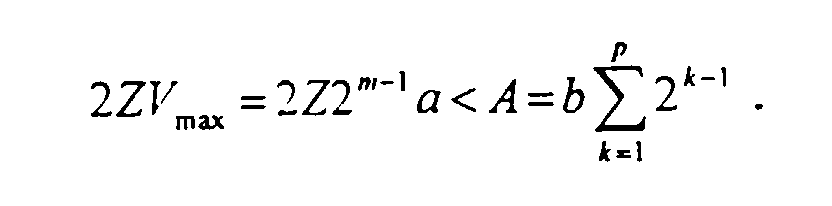
- the maximum charging weight difference W max which may be generated is twice as great as the weight of the articles whose bulk density has a reference value d that are supplied into the maximum additive storage cup. If the total weight of the articles within the additive auxiliary cups is greater than the maximum charging weight difference W max , it is possible to make up the maximum charging weight difference W max by selecting the combination of the additive auxiliary cups. More specifically, if the total capacity of the p additive auxiliary cups is expressed by A, the following relationship should be obtained.
- the large charging storage cup can be formed by a main charging storage cup and a subtractive auxiliary cup.
- the subtractive auxiliary cup holds the articles without discharge so that the maximum charging weight difference w max can be decreased.
- the apparatus may have a structure in which the capacity of the subtractive auxiliary cup is set so as to store the articles having a weight of (2ZdV max ad) to (2ZdV max + ad). According to such a structure, it is possible to perform correction so as to almost offset the maximum charging weight difference W max .
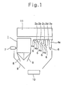
- Fig. 1 shows the schematic structure of a quantitative charging apparatus as an example.
- the quantitative charging apparatus is used to charge a predetermined container such as a box or a bag with articles having a target weight W o , and comprises a large charging storage cup 1 and five additive storage cups 4a to 4e for storing the articles.
- Articles are supplied from a charging apparatus 11 into the large charging storage cup 1 and the five additive storage cups 4a to 4e with even cupfuls at almost the same time.
- the large charging storage cup 1 has a load cell 7.
- the articles for large charging which are supplied into the large charging storage cup 1 are weighed by the load cell 7.
- the five additive storage cups 4a to 4e have load cells 2a to 2e respectively by which the articles for additive charging are weighed.
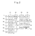
- the outputs of the load cells 7 and 2a to 2e are input to a control device which has a circuit shown in Fig. 2.
- a gate 8 for discharging the articles is disposed in a bottom portion of the large charging storage cup 1, while five gates 6 which open and close independently of each other are disposed in the additive storage cups 4a to 4e respectively.
- the articles within the large charging storage cup 1 and the additive storage cups 4a to 4e are discharged into a container 10 such as a box or a bag through a chute 9.
- the gate 8 and the five gates 6 open and close under the control of the aforementioned control device.
- the output of the load cell 7 which weighs the articles supplied into the large charging storage cup 1 and the outputs of the load cells 2a to 2e which weigh the articles supplied into the additive storage cups 4a to 4e are amplified by amplifiers 21 and connected to a multiplexer 22.
- the multiplexer 22 switches the output of each amplifier 21 by time sharing. Then, the switched output is input to an A/D converter 23.
- the A/D converter 23 converts the input analog data to digital data to be processed by a CPU (central processing unit) 24.
- the CPU 24 performs processing according to a program stored in a ROM (read only memory) 25. In this case, a RAM (random access memory) 26 is temporarily used.
- Data such as a target weight W o , the bulk density of the articles and the like are input to and stored in a nonvolatile RAM 30 through a keyboard 27.
- the opening and closing of the gate 8 and the five gates 6 based on the result of processing of the CPU 24 are controlled through an input-output 28.
- An indicator 29 indicates the weight of the articles which are filled, a value set to the nonvolatile RAM 30 and the like.
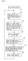
- the apparatus of the present example performs quantitative charging according to a flowchart shown in Fig. 3.
- the container 10 is set in a lower portion of the chute 9.
- the articles are supplied from the charging apparatus 11 to the large charging storage cup 1 and the five additive storage cups 4a to 4e.
- the articles which are supplied into the large charging storage cup 1 are weighed as a large charging weight W a by the load cell 7 .
- the articles which are supplied into the additive storage cups 4a to 4e are weighed by the load cells 2a to 2e.
- the combination of the additive storage cups is selected in such a manner that the underweight W d becomes the closest to 0.
- the articles within the selected additive storage cups are discharged together with the articles within the large charging storage cup 1 and then supplied into the container 10. Further, the filled container is replaced with an empty container at Step 38, and weighing is then repeated from Step 32.
- the capacity ratio among the additive storage cups 4a to 4e is 1:2:4:8:16.
- the weighing of the large charging weight W a is performed simultaneously with that of the articles within each additive storage cup.
- the calculation for obtaining the underweight W d and the selection of the combination of the additive storage cups having capacities which are the closest to the underweight W d are performed at a high speed by the CPU 24. Consequently, the charging speed is very high.
- the present invention is not restricted thereto and the number of the additive storage cups can be selected. While the case where a positive integer r is 2 has been described in the above example, the present invention is not restricted thereto and other integers or decimal numbers can be selected.
- the quantitative charging apparatus comprises a large charging storage cup for large charging, and a plurality of additive storage cups having at least two kinds of capacities for performing additive charging to make up the large charging. Consequently, the weights of the articles can be controlled and adjusted finer within the wide range. Since the weighing of the large charging weight W a is performed simultaneously with that of the articles within the additive storage cups, the charging speed is very high. In addition, the calculation for obtaining the underweight W d and the selection of the combination of the additive storage cups having capacities which are the closest to the underweight W d can be performed at a high speed by a computer or the like. Consequently, the charging speed is increased.
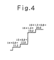
- the bulk densities of the articles within the additive storage cups 4a to 4e having a capacity ratio of 1:2:4:8 are increased by 20% and the bulk density of the articles within the additive storage cup 4e having a capacity ratio of 16 is decreased by 20%.
- the value of 12.8 can be made up by the combination of other additive storage cups 4a to 4d.
- the additive storage cup 4e has no significance.
- the articles for addition which are prepared have weights of 11.2, 12.0, 19.2 and 20.0.
- the following quantitative charging apparatus has a structure in which the weights of the articles can be adjusted finer within the wide range even if the bulk densities of the articles are changed.
- Fig. 5 shows the schematic structure of a quantitative charging apparatus according to an embodiment of the present invention.
- the quantitative charging apparatus according to the present embodiment is used to charge a predetermined container such as a box or a bag with articles having a target weight W o , and comprises a large charging storage cup 1 for storing the articles for large charging, five additive storage cups 4a to 4e for additive charging, and three additive auxiliary cups 14a to 14c for correcting the charging weight difference.
- articles are supplied from a charging apparatus 11 into the large charging storage cup 1, the additive storage cups 4a to 4e and the additive auxiliary cups 14a to 14c with even cupfuls at almost the same time.
- the large charging storage cup 1 has a load cell 7.
- the articles which are supplied into the large charging storage cup 1 are weighed by the load cell 7.
- the five additive storage cups 4a to 4e have load cells 2a to 2e respectively by which the articles for additive charging are weighed respectively.
- the additive auxiliary cups 14a to 14c have load cells 12a to 12c respectively.
- the outputs of the load cells 7, 2a to 2e and 12a to 12c are input to a control device (not shown).
- a gate 8 for discharging the articles are disposed in a bottom portion of the large charging storage cup 1, while gates 6 and 16 which open and close independently of each other are disposed in the additive storage cups 4a to 4e and the additive auxiliary cups 14a to 14c respectively.
- the articles within the large charging storage cup 1, the additive storage cups 4a to 4e and the additive auxiliary cups 14a to 14c are discharged into a container 10 such as a box or a bag through a chute 9.
- the gates 8, 6 and 16 open and close under the control of the aforementioned control device which is not shown.
- the number p of the additive auxiliary cups is 3(7ad) according to the present embodiment.
- the additive auxiliary cups 14a to 14c having the same capacities as those of the three smaller additive storage cups 4a to 4c are provided. Consequently, a maximum charging weight difference W max 6.4ad which is obtained by the structure of the present embodiment can be corrected by the same charging weight difference as that of the additive storage cups 4a to 4c.
- Fig. 6 is the schematic structure of a quantitative charging apparatus according to another embodiment of the present invention.
- the apparatus of the present embodiment differs from the apparatus shown in Fig. 5 in the following respects. More specifically, the apparatus shown in Fig. 6 has a single additive auxiliary cup 14 including a load cell 12 in place of the additive auxiliary cups 14a to 14c, and a large charging storage cup 1 is formed by a main charging storage cup la having a gate 8a and a subtractive auxiliary cup 1b having a gate 8b.
- the articles for large charging are supplied to the main charging storage cup la and the subtractive auxiliary cup 1b separately.
- the articles filled into the main charging storage cup la and the subtractive auxiliary cup 1b are weighed by load cells 7a and 7b.
- the same reference numbers designate the same components as in Fig. 5.
- the capacities of the additive auxiliary cup 14 and subtractive auxiliary cup 1b are 6.4a.
- Fig. 7 (a) shows the case where the articles for additive charging are increased every minimum unit capacity by changing the combination of the additive storage cups.
- ad is omitted in Figs. 7 and 8.
- Fig. 8 (a) shows the case where the articles for addition are increased every minimum unit capacity by changing the combination of the additive storage cups.
- the additive storage cup 4a having the minimum unit volume is added and the articles for addition have a weight of 12.0ad (a capacity ratio of 15) which is the total weight of the articles within the additive storage cups 4a to 4d.
- the present invention is not restricted thereto but can be applied to an apparatus including a plurality of additive storage cups which have at least two kinds of capacities.
- the number of the additive auxiliary cups can be selected.
- the present invention is not restricted thereto but other integers or decimal numbers can be selected. Furthermore, the positive real numbers s and t, and b and a may be different from each other respectively. In this case, the difference in charging weight which is obtained by only the additive storage cups is not the same as the difference in charging weight which is obtained by adding the additive auxiliary cup.
- the gap in the charging weight difference which is caused by changing the bulk densities of the articles supplied into the additive storage cups is corrected by the additive auxiliary cup having the number and capacity corresponding to the gap.
- the articles can be adjusted finer within the wide range even if the bulk densities of the articles are changed.
- the articles within the subtractive auxiliary cup are not discharged but held so that the maximum charging weight difference W max can be decreased. Consequently, the weight can be adjusted within the wide range.
Landscapes
- Physics & Mathematics (AREA)
- General Physics & Mathematics (AREA)
- Basic Packing Technique (AREA)
- Beverage Vending Machines With Cups, And Gas Or Electricity Vending Machines (AREA)
- Weight Measurement For Supplying Or Discharging Of Specified Amounts Of Material (AREA)
Claims (9)
- Appareil de chargement quantitatif comportant :caractérisé en ce que l'appareil comporte, en outre :un récipient de stockage principal (1) doté de moyens de pesée (7) ;plusieurs récipients de stockage additifs (4a à 4e) d'au moins deux capacités différentes, dotés chacun de moyens de pesée (2a à 2e), pour assurer un chargement additif afin de compenser une insuffisance de poids correspondant à la différence entre le poids de produits se trouvant ans le récipient de stockage principal (1) et un poids cible, les capacités des récipients de stockage additifs (4a à 4e) étant telles que des combinaisons successives des récipients de stockage additifs (4a à 4e) ont pour résultat des augmentations de capacité inférieures ou égales à une unité prédéterminée ; etdes moyens de commande pour sélectionner une combinaison appropriée de récipients de stockage additifs (4a à 4e) pour compenser l'insuffisance de poids ;au moins un récipient de stockage auxiliaire (14a à 14c) doté de moyens de pesée (12a à 12c) ;l'un au moins des récipients de stockage auxiliaires (14a à 14c) étant sélectionné lorsqu'une variation de la densité apparente de produits se trouvant dans les récipients de stockage additifs est telle que des combinaisons successives des récipients de stockage additifs (4a à 4e) ont pour résultat des augmentations de poids supérieures à ladite unité prédéterminée.
- Appareil de chargement quantitatif selon la revendication 1, dans lequel lesdits récipients de stockage additifs (4a à 4e) comprenant au moins m récipients de stockage additifs ayant les capacités suivantes :
a, as1, as2, ..., ask-1, ..., asm-1a représentant la capacité d'un récipient de stockage additif utilisé comme référence ;s représentant un nombre réel positif ;0 < k (nombre entier) <= m, m <= le nombre desdits récipients de stockage additifs. - Appareil de chargement quantitatif selon la revendication 1 ou la revendication 2, dans lequel il y a plusieurs récipients auxiliaires additifs (14a à 14c) comprenant au moins p récipients auxiliaires additifs ayant les capacités suivantes :
b, bt1, bt2, ..., btk-1, btp-1b représentant la capacité d'un récipient auxiliaire additif utilisé comme référencet représentant un nombre réel positif0 < k (nombre entier) <= p. - Appareil de chargement quantitatif selon la revendication 3, dans lequel lesdits nombres réels positifs t et s sont égaux.
- Appareil de chargement quantitatif selon la revendication 4, dans lequel lesdits nombres réels positifs t et s sont 2.
- Appareil de chargement quantitatif selon la revendication 5, dans lequel lorsque le rapport de dispersion maximal des densités apparentes des produits se trouvant dans lesdits récipients de stockage additifs (4a à 4e) est Z, le volume maximal desdits m récipients de stockage additifs (4a à 4e) est Vmax, et la capacité totale desdits p récipients auxiliaires additifs (14 à 14c) est A, le nombre p desdits récipients auxiliaires additifs (14a à 14c) étant un nombre entier qui satisfait l'équation suivante :
- Appareil de chargement quantitatif selon les revendications 1 à 6, dans lequel ledit récipient de stockage principal (1) comprend un récipient de stockage de chargement principal (1a) et un récipient auxiliaire soustractif (1b) dotés chacun de moyens de pesée respectifs (7a, 7b), ledit récipient auxiliaire soustractif (1b) étant destiné à contenir des produits sans les décharger.
- Appareil de chargement quantitatif selon la revendication 7, dans lequel ledit récipient auxiliaire additif (14) est un récipient unique, ledit récipient auxiliaire additif (14) et ledit récipient auxiliaire soustractif (1b) ayant des capacités leur permettant de stocker les produits ayant un poids allant de (2ZdVmax - ad) à (2ZdVmax + ad) lorsque le volume maximal desdits récipients de stockage additifs (4a à 4e) est égal à Vmax.
- Procédé de chargement de produits jusqu'à un poids cible, comprenant le chargement d'un récipient de stockage principal (1), le calcul de la différence entre le poids cible et le poids des produits se trouvant dans le récipient de stockage principal (1), la sélection d'une combinaison de récipients de stockage additifs (4a à 4e) en fonction de la capacité requise pour compenser la différence, et la pesée des produits se trouvant dans lesdits récipients de stockage additifs (4a à 4e), caractérisé en ce qu'au moins un récipient de stockage auxiliaire (14a à 14c) est sélectionné lorsque le poids combiné des produits se trouvant dans les récipients de stockage additifs (4a à 4e) dépasse une valeur admissible en raison d'une variation de la densité apparente des produits présents dans ces derniers.
Applications Claiming Priority (6)
| Application Number | Priority Date | Filing Date | Title |
|---|---|---|---|
| JP8103495 | 1995-04-06 | ||
| JP8103495A JPH08278189A (ja) | 1995-04-06 | 1995-04-06 | 定量充填装置 |
| JP81034/95 | 1995-04-06 | ||
| JP12130295A JP3571797B2 (ja) | 1995-05-19 | 1995-05-19 | 定量充填装置 |
| JP121302/95 | 1995-05-19 | ||
| JP12130295 | 1995-05-19 |
Publications (2)
| Publication Number | Publication Date |
|---|---|
| EP0736754A1 EP0736754A1 (fr) | 1996-10-09 |
| EP0736754B1 true EP0736754B1 (fr) | 2000-06-21 |
Family
ID=26422075
Family Applications (1)
| Application Number | Title | Priority Date | Filing Date |
|---|---|---|---|
| EP96302275A Expired - Lifetime EP0736754B1 (fr) | 1995-04-06 | 1996-03-29 | Dispositif pour charger un récipient avec des articles pesés |
Country Status (5)
| Country | Link |
|---|---|
| US (2) | US5910646A (fr) |
| EP (1) | EP0736754B1 (fr) |
| CN (1) | CN1111278C (fr) |
| AU (1) | AU686501B2 (fr) |
| DE (1) | DE69608925T2 (fr) |
Families Citing this family (22)
| Publication number | Priority date | Publication date | Assignee | Title |
|---|---|---|---|---|
| US7057118B2 (en) * | 2001-04-24 | 2006-06-06 | Skaginn Hf | Method and an apparatus for weighing portions |
| DK1421352T3 (da) * | 2001-07-17 | 2009-01-26 | Marel Food Systems Hf | Fremgangsmåde og indretning til portionering af emner |
| JP4233267B2 (ja) * | 2002-04-16 | 2009-03-04 | 大和製衡株式会社 | 粉粒体計量装置及び粉粒体計量方法 |
| EP1515125A1 (fr) * | 2003-09-11 | 2005-03-16 | Cabinplant International A/S | Dispositif et procédé de pesage et de mise en lot d'articles |
| JPWO2006003706A1 (ja) * | 2004-07-02 | 2008-04-17 | 株式会社プラスワンテクノ | 組み合わせ計量技術 |
| US20090107859A1 (en) * | 2007-10-24 | 2009-04-30 | Kai Hui Cai | Beverage container with integral storage space for drinking cups |
| US9959511B2 (en) | 2010-12-08 | 2018-05-01 | Bayer Cropscience Lp | Retail point seed treatment systems and methods |
| UA109920C2 (uk) | 2010-12-08 | 2015-10-26 | Байєр Кропсайєнс Елпі | Виробничі бази, способи і пристрій для обробки насіння |
| US9861027B2 (en) | 2010-12-08 | 2018-01-09 | Bayer Cropscience, Lp | Seed treatment systems and methods |
| WO2012098592A1 (fr) * | 2011-01-20 | 2012-07-26 | 大和製衡株式会社 | Dispositif de pesage |
| CN102424125B (zh) * | 2011-08-03 | 2014-01-15 | 合肥通用机械研究院 | 一种用于散粒料容积式组合计量法的计量装置 |
| CN102636241B (zh) * | 2012-04-24 | 2013-09-04 | 长城金银精炼厂 | 一种金条自动配重系统及其配重方法 |
| US20180045555A1 (en) * | 2015-03-06 | 2018-02-15 | Ishida Co., Ltd. | Mix weighing device |
| CN106444552A (zh) * | 2016-11-29 | 2017-02-22 | 梧州学院 | 一种多路定量称重控制仪表电路及其控制方法 |
| EP3617670B1 (fr) * | 2017-04-28 | 2024-12-04 | Shozo Kawanishi | Dispositif de pesée |
| US11402255B2 (en) | 2017-04-28 | 2022-08-02 | Shozo Kawanishi | Compact weighing apparatus including rough-charge weigher and combination weigher |
| CN109496267B (zh) * | 2017-07-13 | 2020-08-07 | 大和制衡株式会社 | 组合计量装置 |
| CN110433078A (zh) * | 2018-05-02 | 2019-11-12 | 深圳市卫邦科技有限公司 | 一种基于配药机器人的药品抽吸方法及配药机器人 |
| CN112729497A (zh) * | 2021-01-19 | 2021-04-30 | 湖北航鹏化学动力科技有限责任公司 | 一种药剂高效称量方法及设备 |
| CN114308704B (zh) * | 2022-01-05 | 2024-08-27 | 北京柏炜智能设备有限公司 | 一种配重分拣系统及方法 |
| CN114904453B (zh) * | 2022-05-17 | 2023-12-29 | 广西强强碳素股份有限公司 | 铝电解用预焙阳极生产煅烧工序精准配料系统 |
| CN116514423B (zh) * | 2023-05-22 | 2024-07-19 | 安徽庆丰涂料科技有限公司 | 一种轻质抹灰石膏全自动生产装置及其生产方法 |
Family Cites Families (19)
| Publication number | Priority date | Publication date | Assignee | Title |
|---|---|---|---|---|
| DE2227965A1 (de) * | 1972-06-08 | 1974-01-03 | Albert Welter | Zuteilvorrichtung fuer die fuellung von formen in pressen |
| JPS546221B2 (fr) * | 1974-03-08 | 1979-03-26 | ||
| US4538692A (en) * | 1982-02-01 | 1985-09-03 | Kliklok Corporation | Method and apparatus for combination weighing with multiple storage cups for each scale hopper |
| AU544807B2 (en) * | 1982-06-23 | 1985-06-13 | Ishida Koki Seisakusho K.K. | Combination weigher |
| JPS59120822A (ja) * | 1982-12-17 | 1984-07-12 | ヘンリ−,ジヨン,ステイ−ル | 組合せ計量装置 |
| US4534480A (en) * | 1984-06-01 | 1985-08-13 | Sun Coast Plastics, Inc. | Tamper evident closure |
| AU572680B2 (en) * | 1984-08-09 | 1988-05-12 | Ishida Scales Mfg. Co. Ltd. | Weighing machine |
| JPS629226A (ja) * | 1985-07-05 | 1987-01-17 | Kawasaki Steel Corp | 計量方法および装置 |
| DE3540165A1 (de) * | 1985-11-13 | 1987-05-21 | Schenck Ag Carl | Verfahren und vorrichtung zur feindosierung von schuettguetern |
| JPH0610629B2 (ja) * | 1985-12-02 | 1994-02-09 | 大和製衡株式会社 | 組合せ秤 |
| EP0253895B1 (fr) * | 1985-12-29 | 1992-11-19 | Anritsu Corporation | Appareil de pesage combine |
| DD270978B5 (de) * | 1986-04-02 | 1993-10-28 | Ver Energiewerke Ag | Verfahren zur bestimmung der schuettdichte eines foerderstromes |
| JPH0517623Y2 (fr) * | 1986-05-21 | 1993-05-12 | ||
| US4901807A (en) * | 1986-10-31 | 1990-02-20 | Triangle Package Machinery | Combination weigher with multiple compartment weighing receptacles |
| US4828054A (en) * | 1988-06-29 | 1989-05-09 | Package Machinery Company | Combination weigher having a standby product charge |
| JP2703986B2 (ja) * | 1989-04-07 | 1998-01-26 | 大和製衡株式会社 | 組合せ秤 |
| JP3083861B2 (ja) * | 1991-03-14 | 2000-09-04 | 大和製衡株式会社 | 分散供給装置の制御方法及び装置 |
| JP3124369B2 (ja) * | 1992-04-14 | 2001-01-15 | 大和製衡株式会社 | 複数台の組合せ秤における操作表示装置 |
| DE69530472T2 (de) * | 1994-08-26 | 2003-10-30 | Anritsu Industrial Solutions Co., Ltd. | Kombinationswaage |
-
1996
- 1996-03-29 DE DE69608925T patent/DE69608925T2/de not_active Expired - Lifetime
- 1996-03-29 EP EP96302275A patent/EP0736754B1/fr not_active Expired - Lifetime
- 1996-04-04 AU AU50512/96A patent/AU686501B2/en not_active Expired
- 1996-04-05 US US08/628,491 patent/US5910646A/en not_active Expired - Lifetime
- 1996-04-06 CN CN96105773A patent/CN1111278C/zh not_active Expired - Lifetime
-
1998
- 1998-12-01 US US09/203,452 patent/US5981882A/en not_active Expired - Lifetime
Also Published As
| Publication number | Publication date |
|---|---|
| DE69608925T2 (de) | 2001-01-04 |
| AU686501B2 (en) | 1998-02-05 |
| CN1111278C (zh) | 2003-06-11 |
| CN1139205A (zh) | 1997-01-01 |
| DE69608925D1 (de) | 2000-07-27 |
| US5981882A (en) | 1999-11-09 |
| US5910646A (en) | 1999-06-08 |
| EP0736754A1 (fr) | 1996-10-09 |
| AU5051296A (en) | 1996-10-24 |
Similar Documents
| Publication | Publication Date | Title |
|---|---|---|
| US5910646A (en) | Quantitative charging apparatus | |
| US5894111A (en) | Quantitative charging apparatus | |
| US4548286A (en) | Combinatorial weighing method and apparatus with volume and density sensing | |
| US4967856A (en) | Combination weighing machine | |
| US4901807A (en) | Combination weigher with multiple compartment weighing receptacles | |
| US4753306A (en) | Combination weighing method and apparatus using multi-bin scales | |
| WO2003036243A1 (fr) | Dispositif pour peser des materiaux pulverulents et granuleux | |
| JP3402687B2 (ja) | 組合せ計量または計数方法および組合せ計量または計数装置 | |
| EP1355137B1 (fr) | Procédé de pesage de poudres | |
| JPH08313327A (ja) | 定量充填装置 | |
| JPH08278189A (ja) | 定量充填装置 | |
| EP0911617B1 (fr) | Procédé pour peser des éclats ou de la poudre | |
| EP0643288B1 (fr) | Pesées combinées à auto adaption | |
| JP3509989B2 (ja) | 定量充填装置 | |
| JP3388832B2 (ja) | 組合せ計量または計数方法および組合せ計量または計数装置 | |
| CN115200682B (zh) | 一种料仓仓位的检测及控制方法、系统 | |
| JPH0251131B2 (fr) | ||
| JP3305816B2 (ja) | 組合せ計量装置 | |
| JP4608110B2 (ja) | 組合せ計量装置 | |
| JP2512856B2 (ja) | 組合せ計量装置 | |
| JP3571798B2 (ja) | 定量充填装置 | |
| JP2003207384A (ja) | 粉粒体計量装置及び粉粒体計量方法 | |
| JPH0543976B2 (fr) | ||
| JP3439525B2 (ja) | 優先処理装置付き組合せ秤 | |
| JP4152735B2 (ja) | 組合せ計量装置 |
Legal Events
| Date | Code | Title | Description |
|---|---|---|---|
| PUAI | Public reference made under article 153(3) epc to a published international application that has entered the european phase |
Free format text: ORIGINAL CODE: 0009012 |
|
| AK | Designated contracting states |
Kind code of ref document: A1 Designated state(s): CH DE FR GB IT LI |
|
| 17P | Request for examination filed |
Effective date: 19961009 |
|
| 17Q | First examination report despatched |
Effective date: 19990201 |
|
| GRAG | Despatch of communication of intention to grant |
Free format text: ORIGINAL CODE: EPIDOS AGRA |
|
| GRAG | Despatch of communication of intention to grant |
Free format text: ORIGINAL CODE: EPIDOS AGRA |
|
| GRAH | Despatch of communication of intention to grant a patent |
Free format text: ORIGINAL CODE: EPIDOS IGRA |
|
| GRAH | Despatch of communication of intention to grant a patent |
Free format text: ORIGINAL CODE: EPIDOS IGRA |
|
| GRAA | (expected) grant |
Free format text: ORIGINAL CODE: 0009210 |
|
| AK | Designated contracting states |
Kind code of ref document: B1 Designated state(s): CH DE FR GB IT LI |
|
| REG | Reference to a national code |
Ref country code: CH Ref legal event code: EP |
|
| REF | Corresponds to: |
Ref document number: 69608925 Country of ref document: DE Date of ref document: 20000727 |
|
| REG | Reference to a national code |
Ref country code: CH Ref legal event code: NV Representative=s name: KIRKER & CIE SA |
|
| ET | Fr: translation filed | ||
| ITF | It: translation for a ep patent filed | ||
| PLBE | No opposition filed within time limit |
Free format text: ORIGINAL CODE: 0009261 |
|
| STAA | Information on the status of an ep patent application or granted ep patent |
Free format text: STATUS: NO OPPOSITION FILED WITHIN TIME LIMIT |
|
| 26N | No opposition filed | ||
| REG | Reference to a national code |
Ref country code: GB Ref legal event code: IF02 |
|
| REG | Reference to a national code |
Ref country code: FR Ref legal event code: PLFP Year of fee payment: 20 |
|
| PGFP | Annual fee paid to national office [announced via postgrant information from national office to epo] |
Ref country code: IT Payment date: 20150224 Year of fee payment: 20 Ref country code: DE Payment date: 20150324 Year of fee payment: 20 Ref country code: CH Payment date: 20150313 Year of fee payment: 20 |
|
| PGFP | Annual fee paid to national office [announced via postgrant information from national office to epo] |
Ref country code: FR Payment date: 20150309 Year of fee payment: 20 Ref country code: GB Payment date: 20150325 Year of fee payment: 20 |
|
| REG | Reference to a national code |
Ref country code: DE Ref legal event code: R071 Ref document number: 69608925 Country of ref document: DE |
|
| REG | Reference to a national code |
Ref country code: CH Ref legal event code: PL |
|
| REG | Reference to a national code |
Ref country code: GB Ref legal event code: PE20 Expiry date: 20160328 |
|
| PG25 | Lapsed in a contracting state [announced via postgrant information from national office to epo] |
Ref country code: GB Free format text: LAPSE BECAUSE OF EXPIRATION OF PROTECTION Effective date: 20160328 |