EP0737010A2 - Aufnahme- und Wiedergabegerät für magnetische Aufzeichnungen unter Verwendung eines Referenzpegels - Google Patents
Aufnahme- und Wiedergabegerät für magnetische Aufzeichnungen unter Verwendung eines Referenzpegels Download PDFInfo
- Publication number
- EP0737010A2 EP0737010A2 EP96107017A EP96107017A EP0737010A2 EP 0737010 A2 EP0737010 A2 EP 0737010A2 EP 96107017 A EP96107017 A EP 96107017A EP 96107017 A EP96107017 A EP 96107017A EP 0737010 A2 EP0737010 A2 EP 0737010A2
- Authority
- EP
- European Patent Office
- Prior art keywords
- signal
- frequency
- level
- reproduced
- recording
- Prior art date
- Legal status (The legal status is an assumption and is not a legal conclusion. Google has not performed a legal analysis and makes no representation as to the accuracy of the status listed.)
- Ceased
Links
Images




Classifications
-
- H—ELECTRICITY
- H04—ELECTRIC COMMUNICATION TECHNIQUE
- H04N—PICTORIAL COMMUNICATION, e.g. TELEVISION
- H04N9/00—Details of colour television systems
- H04N9/79—Processing of colour television signals in connection with recording
- H04N9/7908—Suppression of interfering signals at the reproducing side, e.g. noise
-
- H—ELECTRICITY
- H04—ELECTRIC COMMUNICATION TECHNIQUE
- H04N—PICTORIAL COMMUNICATION, e.g. TELEVISION
- H04N5/00—Details of television systems
- H04N5/76—Television signal recording
- H04N5/91—Television signal processing therefor
- H04N5/911—Television signal processing therefor for the suppression of noise
-
- H—ELECTRICITY
- H04—ELECTRIC COMMUNICATION TECHNIQUE
- H04N—PICTORIAL COMMUNICATION, e.g. TELEVISION
- H04N5/00—Details of television systems
- H04N5/76—Television signal recording
- H04N5/91—Television signal processing therefor
- H04N5/92—Transformation of the television signal for recording, e.g. modulation, frequency changing; Inverse transformation for playback
- H04N5/923—Transformation of the television signal for recording, e.g. modulation, frequency changing; Inverse transformation for playback using preemphasis of the signal before modulation and deemphasis of the signal after demodulation
-
- H—ELECTRICITY
- H04—ELECTRIC COMMUNICATION TECHNIQUE
- H04N—PICTORIAL COMMUNICATION, e.g. TELEVISION
- H04N9/00—Details of colour television systems
- H04N9/79—Processing of colour television signals in connection with recording
- H04N9/793—Processing of colour television signals in connection with recording for controlling the level of the chrominance signal, e.g. by means of automatic chroma control circuits
- H04N9/7933—Processing of colour television signals in connection with recording for controlling the level of the chrominance signal, e.g. by means of automatic chroma control circuits the level control being frequency-dependent
-
- H—ELECTRICITY
- H04—ELECTRIC COMMUNICATION TECHNIQUE
- H04N—PICTORIAL COMMUNICATION, e.g. TELEVISION
- H04N9/00—Details of colour television systems
- H04N9/79—Processing of colour television signals in connection with recording
- H04N9/80—Transformation of the television signal for recording, e.g. modulation, frequency changing; Inverse transformation for playback
- H04N9/82—Transformation of the television signal for recording, e.g. modulation, frequency changing; Inverse transformation for playback the individual colour picture signal components being recorded simultaneously only
- H04N9/83—Transformation of the television signal for recording, e.g. modulation, frequency changing; Inverse transformation for playback the individual colour picture signal components being recorded simultaneously only the recorded chrominance signal occupying a frequency band under the frequency band of the recorded brightness signal
Definitions
- the invention relates to magnetic recording and reproducing apparatuses such as home VTRs in which a luminance signal of a video signal to be recorded is subjected to frequency modulation and then to single-sideband recording.
- the frequency band of signals which can be recorded and reproduced is generally narrower than the frequency band of a frequency-modulated (FM) luminance signal of a video signal to be recorded and, as a result, high-frequency components of the upper sideband of this FM signal are neither recorded nor reproduced. It is for this reason that the FM signal takes the form of a single-sideband wave when recorded and involves an amplitude variation when reproduced. If this FM signal is demodulated with its amplitude variation removed by a limiter, the aforesaid high frequencies of its upper sideband can be recovered. This is how the single-sideband recording is performed.
- FM frequency-modulated
- the modulation indices of the high-frequency components of its recovered upper sideband and the low-frequency components of its lower sideband are decreased, and this acts to decrease the level of the FM signal.
- the energy of the high-frequency components of its demodulated luminance signal becomes smaller than that of its low-frequency components, thereby decreasing the signal level as a whole.
- the home VTR employs a peaking circuit to boost the high-frequency components of the demodulated luminance signal. This peaking circuit serves to keep the level of the high-frequency components of the demodulated luminance signal as high as that of its low-frequency components.
- video tapes for the home VTRs include normal tapes and so-called "high-grade tapes" that exhibit higher performance than the normal tapes.
- high-grade tapes the characteristics of a recording or reproducing system of a VTR must be differentiated between high-grade tapes and normal tapes. For example, the following means could be proposed to implement such differentiation.
- an input terminal 1 receives a video signal from a not shown TV receiver or the like. This video signal is applied to a LPF 2, where a luminance signal is extracted, and the extracted luminance signal is then applied to an AGC 3, which controls the applied signal in such a manner that the level of its synchronizing signal can be kept constant.
- the video signal fed to the input terminal 1 is also applied to a not shown BPF, where a chroma signal is extracted, and the extracted chroma signal is then converted into a low-frequency signal at a not shown chroma signal processing circuit.
- the luminance signal which has been through with the AGC 3 is then fed to a detail emphasis circuit 4, where small-level signal components in high-frequency components of the luminance signal are emphasized, and the emphasized signal is then applied to a luminance signal processing circuit 5.
- the high frequencies are subjected to emphasis and a like process and then applied to a frequency modulator 6.
- the luminance signal frequency-modulated at the frequency modulator 6 has its low frequencies boosted by an FM equalizer 7, and low frequencies that correspond to the band of the low-frequency converted chroma signal are cut off at a HPF 8.
- the FM luminance signal which has been through with the HPF 8 is then applied to a recording amplifier 9, where it is amplified while mixed with the low-frequency converted chroma signal from the input terminal 10, and the thus processed signal is then supplied to a video head 11 to be magnetically recorded on a video tape 12.
- a video head 13 though shown separately from the video head 11 for purposes of convenience, is the same as the video head 11.
- a video signal reproduced from the video head 13 is amplified by a preamplifier 14, and not only a chroma signal that is subjected to low-frequency conversion by a LPF 15 is extracted but also a luminance signal that is frequency-modulated by a HPF 16 is extracted.
- the chroma signal which has been through with the LPF 15 is converted into a chroma signal of a subcarrier band by a chroma signal processing circuit 17 and the converted chroma signal is then supplied to a mixing circuit 18.
- the luminance signal which has been through with the HPF 16 has its high-frequency components (around 5 MHz) boosted by an FM equalizer 19, is kept at a constant level by an FM AGC 20 thereafter, and is then demodulated when applied to a frequency demodulator 21.
- the luminance signal delivered from the FM demodulator 21 is appropriately processed by a luminance signal processing circuit 22, and has its high-frequency components (2 MHz or more) boosted by a subsequent peaking circuit 23.
- the luminance signal which has been through with the peaking circuit 23 is applied to a line noise canceller 24.
- the line noise canceller 24 delays a luminance signal fed from an input terminal 27 via the peaking circuit 23 for a single horizontal scanning period (hereinafter referred to simply as "1H") by a 1H delay element 28.
- the thus delayed luminance signal and the original luminance signal that has not been delayed are subjected to subtraction at a subtractor (which is shown as an adder 29, but acts as a subtractor because its polarity is inverted by the 1H delay element 28).
- a subtractor which is shown as an adder 29, but acts as a subtractor because its polarity is inverted by the 1H delay element 28.
- Only a small-level signal which can be deemed as a noise component is extracted from the subtracted signal by a limiter 30, and the level of this small-level signal is attenuated by 1/2 at an attenuator 31.
- the attenuated signal is then subtracted by a subtractor shown as an adder 32, so that the noise component can be canceled.
- the noise canceller 25 extracts high-frequency components containing much noise from the luminance signal that has been through with the line noise canceller 24, and components whose levels are greater than a predetermined level are removed from the high-frequency components by a slice circuit (not shown). The output of the slice circuit is then subtracted from the luminance signal that has been through with the line noise canceller 24 to cancel the noise.
- the luminance signal which has been through with the noise canceller 25 is applied to the mixing circuit 18 so as to be mixed with the chroma signal, the mixed signal is then delivered to an output terminal 26 and fed to a not shown well known CRT or the like, so that a reproduced image can be obtained.
- the so-called high-grade tapes are commercially available as video tapes for home VTRs.
- the high-grade tape can provide not only a high reproducing output from the tape but also a remarkably improved signal-to-noise ratio by its extremely high degree of granulation and loading of magnetic powder.
- a high-grade tape a1 exhibits an output level higher than a normal tape b1, with the characteristic that its output level becomes higher especially in a high-frequency range (4 to 6 MHz) than in a low-frequency range (1 to 2 MHz).
- the levels of components such as the carrier wave, the low-frequency components of the upper sideband, and the high-frequency components of the lower sideband in the reproduced FM signal are boosted, making the levels of components such as the carrier wave, the low-frequency components of the upper sideband, and the high-frequency components of the lower sideband in the reproduced FM signal that has been through with the limiter 30 higher than in the normal tape. Also, the levels of components such as the high-frequency components of the upper sideband and the low-frequency components of the lower sideband in the reproduced FM signal that has been through with the limiter 30 become relatively lower than the levels of the low-frequency components of the upper sideband and the high-frequency components of the lower sideband as described before.
- Figure 6 shows levels of demodulated video signals for both a high-grade tape a2 and a normal tape b2, indicating that the high-grade tape outputs a lower signal level at high frequencies than the normal tape. It is well known that high-grade tapes produce low reproduced outputs at high frequencies, and this results in blurring reproduced images.
- the detail emphasis circuit 4 which serves to emphasize low-level signal components in high frequencies of a luminance signal to be recorded is provided as described above.
- the aforesaid detail emphasis circuit 4 is made up of a HPF 78, an amplifier 79, a limiter 80, an attenuator 81, an adder 82, and the like.
- a luminance signal received at an input terminal 70 from the AGC 3 is subjected to a process so that its high-frequency components are extracted by the HPF 78, and the extracted components are then amplified by the amplifier 79.
- the amplified high-frequency components are then applied to the limiter 80 so that the small-level signal components are extracted.
- the high-frequency small-level signal components which have been through with the limiter 80 are subjected to level adjustment by the attenuator 81 and to addition thereafter by the adder 82 so as to be added to the luminance signal from the input terminal 70. Then, the thus processed signal is applied to the luminance signal processing circuit 5 via an output terminal 84.
- the noise canceller 25 at which the slice level remains constant regularly cancels any high-frequency low-level signal components, the original signal components other than the noise may also be canceled. For this reason, it is preferable to set the amount of cancellation to a small value for high-grade tapes in which the signal-to-noise ratio is significantly improved but the high-frequency level of their demodulated luminance signal is decreased.
- the line noise canceller shown in Figure 4 does cancel not only noise components but also small-level signal components (detail signals) to a certain degree, thus causing the level of small-level signals to be decreased.
- the level of the deviating signal is decreased as much as such deviation.
- Signals X1 to X5 in Figure 7 show a case of the identical correlation, where X1 is an original signal; and X2, a signal of 1H before. These signals are in phase.
- Signal X3 is an output of the adder 29, which is set to level 0; X4, an output of the attenuator 31, which is likewise set to level 0; and X5, an output of the adder 32, producing a signal identical to the original signal shown by X1.
- Signals Y1 to Y5 show a case where a signal of 1H before is 90° ahead of an original signal, with the original signal and the signal of 1H before being assumed to be such small-level signals as not to be limited by the limiter 30.
- Signal Y4 is an output of the attenuator 31, which is 1/2 the level shown by signal Y3, or ⁇ 2/2 sin( ⁇ - ⁇ /4) .
- the level of the original signal Y1 is decreased by 30% at the stage of the output signal Y5 and the phase of signal Y5 is 45° ahead.
- Small-level signals are generally less correlative in terms of line compared with large-amplitude signals. While no images can be recognized with the large amplitude signals having no line-based correlation, the small-level signals can produce recognizable images with no such correlation. For example, in the case of irregularities of human skin, there is no correlation.
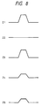
- Signals Z1 to Z5 shown in Figure 8 present a case where there is no correlation between an original signal and a signal of 1H before.
- signal Z1 is a projecting original signal; Z2, a flat signal of 1H before, these signals having such small-amplitudes as not to be limited by the limiter 30; Z3, an output of the adder 29, which has a projecting waveform identical with the original signal; Z4, an output of the attenuator 31, whose amplitude is 1/2 that of the original signal Z1; and Z5, an output of the adder 32, whose amplitude is 1/2 that of the original signal Z1.
- the line noise canceller 24 also decreases the level of the detail signal to some extent, and if there is a deviation from the correlation between the detail signal and the luminance signal of 1H before, the line noise canceller decreases the level of the detail signal as much as that deviation.
- the aforesaid means have heretofore been known to automatically provide an optimal performance of a video tape in accordance with its type such as a normal tape or a high-grade tape, as well as to automatically compensate for deterioration in the characteristic of a video tape in accordance with its type.
- these means are not successful in effectively providing the optimal performance and compensating for the deterioration in the characteristic in accordance with the type of a video tape.
- FM luminance signal component A 3 sin 3 ⁇
- Low-frequency converted chroma signal component B 3 sin 3 ⁇
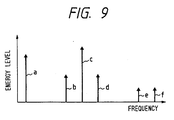
- Figure 9 is a spectrum obtained when a signal magnetized on a video tape has been reproduced.
- Reference character a designates a low-frequency converted chroma signal sin 3 ⁇ ; b, an unwanted component sin( ⁇ - 2 ⁇ ) ; c, an FM luminance signal sin 3 ⁇ ; d, an unwanted component sin( ⁇ + 2 ⁇ ) ; and e, f, unwanted components sin(2 ⁇ - ⁇ ) , sin(2 ⁇ + ⁇ ) , respectively.
- the high-frequency components e, f produce so small output levels that they can be considered negligible.
- the slice level is increased, so that the unwanted components b, d will also be canceled.
- the levels of the unwanted components b, d are low even if a luminance signal is derived from a high-grade tape, thereby causing no mesh noise to appear.
- the object of the invention is to provide a magnetic recording apparatus or a magnetic recording/reproducing apparatus capable of producing a single-wavelength reference signal with using no independent oscillator in a magnetic recording/reproducing apparatus, in which, to automatically control the characteristics of a recording or reproducing system in accordance with the type of a video tape, a single-wavelength reference signal is recorded on and reproduced from the video tape, and the level of the reproduced reference signal is detected and stored.
- a magnetic recording or magnetic recording/reproducing apparatus has a dc voltage source that selectively applies a predetermined level of dc voltage to a frequency modulator, and the output of the frequency modulator obtained by applying the dc voltage to the frequency modulator is used as the reference signal.
- the thus implemented magnetic recording or magnetic recording/reproducing apparatus obtains a single-wavelength reference signal from the frequency modulator by applying the dc voltage from the dc voltage source to the frequency modulator.
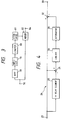
- Figure 1 is a block diagram showing an outline of a main portion of a recording/reproducing system of a home VTR.
- reference numeral 201 designates an input terminal in a recording system.
- This terminal 201 receives a video signal to be recorded from a television receiver or the like.
- the received video signal is applied to a recording luminance signal processing circuit 202, where only a luminance signal is extracted by a LPF or the like.
- a high-frequency chroma signal separated at the circuit 202 is processed by not shown other means.
- the extracted luminance signal is applied to a frequency modulator 204 for frequency modulation.
- the FM luminance signal from the frequency modulator 204 has its low frequencies boosted, and the thus processed luminance signal is then applied to an adder 207 via a HPF 206.
- the adder 207 adds this luminance signal to the low-frequency converted chroma signal from a terminal 208, and the added signal is recorded on a not shown video tape by a video head 211 after having been through with a recording amplifier 209 and a recording/reproducing selector switch 210.
- a color video signal reproduced by the video head 211 from the video tape is supplied to a not shown chroma signal processing circuit and a not shown luminance signal processing circuit via a reproducing preamplifier 212, so that a color image is reproduced by a not shown CRT or the like.
- the above circuits are the same as those used in ordinary home VTRs except for a switch 203.
- reference numeral 213 designates a dc voltage source which is used to provide a predetermined dc voltage to the frequency modulator 204 through the switch 203 in setting the recording and reproducing characteristics so as to match a used video tape.
- the frequency modulator 204 Upon input of the predetermined dc voltage, the frequency modulator 204 outputs a single-wavelength reference signal (e.g., 3.8 MHz) which corresponds to the dc voltage, and this reference signal is recorded on the video tape by the video head 211.
- a single-wavelength reference signal e.g., 3.8 MHz
- the recorded reference signal is reproduced by the video head 211, and fed to a reproduced level detector 214 via the reproducing preamplifier 212.
- the reproduced level of the reference signal detected by the reproduced level detector 214 is stored in a memory 215.
- the reproduced level of the reference signal stored in the memory is compared with the reference voltage of a dc voltage source 217, and a comparison error signal is fed to a control signal generator 218.
- the reference voltage is set to the same level as the reproduced level outputted from the memory 215 when the reference signal is recorded on a reference tape and reproduced therefrom.
- the control signal generator 218 generates a control signal corresponding to the comparison error signal, and the control signal is supplied to a not shown detail emphasis circuit, an FM equalizer 205, both belonging to the recording system, as well as to a not shown FM peaking circuit or a not shown noise canceller, both belonging to the reproducing system, thereby controlling (setting) the recording or reproducing characteristics.
- the switch 203 is connected to the recording luminance signal processing circuit 202, and recording or reproducing of a video signal is performed in a manner described above. Since the recording or reproducing characteristics are adjusted so as to match the video tape characteristics during such recording or reproducing, an optimal performance can be exhibited by the video tape.
Landscapes
- Engineering & Computer Science (AREA)
- Multimedia (AREA)
- Signal Processing (AREA)
- Television Signal Processing For Recording (AREA)
Applications Claiming Priority (11)
| Application Number | Priority Date | Filing Date | Title |
|---|---|---|---|
| JP175131/90 | 1990-07-02 | ||
| JP2175131A JPH0760487B2 (ja) | 1990-07-02 | 1990-07-02 | 磁気記録装置 |
| JP2176593A JPH0468692A (ja) | 1990-07-04 | 1990-07-04 | 磁気再生装置におけるノイズキャンセラ |
| JP176593/90 | 1990-07-04 | ||
| JP2183198A JP2532295B2 (ja) | 1990-07-11 | 1990-07-11 | 磁気記録再生装置 |
| JP183198/90 | 1990-07-11 | ||
| JP2184918A JP2536790B2 (ja) | 1990-07-12 | 1990-07-12 | ラインノイズキャンセラを備えた磁気再生装置 |
| JP184918/90 | 1990-07-12 | ||
| JP194613/90 | 1990-07-23 | ||
| JP2194613A JP2524250B2 (ja) | 1990-07-23 | 1990-07-23 | 磁気記録再生装置 |
| EP91110950A EP0464772B1 (de) | 1990-07-02 | 1991-07-02 | Magnetisches Aufzeichnungs- und Wiedergabegerät |
Related Parent Applications (1)
| Application Number | Title | Priority Date | Filing Date |
|---|---|---|---|
| EP91110950.2 Division | 1991-07-02 |
Publications (2)
| Publication Number | Publication Date |
|---|---|
| EP0737010A2 true EP0737010A2 (de) | 1996-10-09 |
| EP0737010A3 EP0737010A3 (de) | 1997-04-09 |
Family
ID=27528625
Family Applications (5)
| Application Number | Title | Priority Date | Filing Date |
|---|---|---|---|
| EP91110950A Expired - Lifetime EP0464772B1 (de) | 1990-07-02 | 1991-07-02 | Magnetisches Aufzeichnungs- und Wiedergabegerät |
| EP96107017A Ceased EP0737010A3 (de) | 1990-07-02 | 1991-07-02 | Aufnahme- und Wiedergabegerät für magnetische Aufzeichnungen unter Verwendung eines Referenzpegels |
| EP96107016A Withdrawn EP0731605A3 (de) | 1990-07-02 | 1991-07-02 | Magnetisches Wiedergabegerät mit Rauschunterdrücker |
| EP96106993A Withdrawn EP0730375A3 (de) | 1990-07-02 | 1991-07-02 | Magnetisches Aufzeichnungs- und Wiedergabegerät |
| EP96106992A Withdrawn EP0731604A3 (de) | 1990-07-02 | 1991-07-02 | Magnetisches Wiedergabegerät mit Rauschunterdrückung |
Family Applications Before (1)
| Application Number | Title | Priority Date | Filing Date |
|---|---|---|---|
| EP91110950A Expired - Lifetime EP0464772B1 (de) | 1990-07-02 | 1991-07-02 | Magnetisches Aufzeichnungs- und Wiedergabegerät |
Family Applications After (3)
| Application Number | Title | Priority Date | Filing Date |
|---|---|---|---|
| EP96107016A Withdrawn EP0731605A3 (de) | 1990-07-02 | 1991-07-02 | Magnetisches Wiedergabegerät mit Rauschunterdrücker |
| EP96106993A Withdrawn EP0730375A3 (de) | 1990-07-02 | 1991-07-02 | Magnetisches Aufzeichnungs- und Wiedergabegerät |
| EP96106992A Withdrawn EP0731604A3 (de) | 1990-07-02 | 1991-07-02 | Magnetisches Wiedergabegerät mit Rauschunterdrückung |
Country Status (6)
| Country | Link |
|---|---|
| US (4) | US5257109A (de) |
| EP (5) | EP0464772B1 (de) |
| KR (3) | KR100216880B1 (de) |
| DE (1) | DE69125975T2 (de) |
| ES (1) | ES2103757T3 (de) |
| FI (1) | FI913193A7 (de) |
Families Citing this family (18)
| Publication number | Priority date | Publication date | Assignee | Title |
|---|---|---|---|---|
| JP3134434B2 (ja) * | 1991-12-26 | 2001-02-13 | ソニー株式会社 | 記録再生装置 |
| JPH065016A (ja) * | 1992-06-18 | 1994-01-14 | Canon Inc | データ検出装置 |
| JP2948697B2 (ja) * | 1992-06-25 | 1999-09-13 | キヤノン株式会社 | 再生装置 |
| DE69322703T2 (de) * | 1992-07-17 | 1999-07-22 | Mitsubishi Denki K.K., Tokio/Tokyo | Kontrollanordnung für magnetische Aufzeichnung |
| KR970009467B1 (ko) * | 1992-07-21 | 1997-06-13 | 니뽕 빅터 가부시끼 가이샤 | 영상 신호 기록 장치 및 그 재생 장치 |
| US5579119A (en) * | 1992-10-19 | 1996-11-26 | Mitsubishi Denki Kabushiki Kaisha | Recording signal control apparatus capable of optimizing recording conditions for magnetic recording medium |
| JP3167483B2 (ja) * | 1993-02-19 | 2001-05-21 | 株式会社東芝 | 磁気ディスク装置 |
| US5959794A (en) * | 1993-04-09 | 1999-09-28 | Washington University | Method for precompensating signals for magnetic media noise |
| DE4341623A1 (de) * | 1993-12-07 | 1995-06-08 | Mb Video Gmbh | Verfahren zur Rauschunterdrückung und Rauschunterdrückungsschaltung für Videorecorder |
| US5835666A (en) * | 1994-09-22 | 1998-11-10 | Canon Kabushiki Kaisha | Reproducing apparatus including equalizing means which equalizes a reproduced signal when the signal is between a first and second level and varies the response speed |
| JPH08163181A (ja) * | 1994-11-30 | 1996-06-21 | Sharp Corp | 情報再生回路 |
| JP3105761B2 (ja) * | 1995-06-06 | 2000-11-06 | シャープ株式会社 | 自動画質制御装置 |
| US5789883A (en) * | 1996-09-30 | 1998-08-04 | Honeywell Inc. | Pulse duration modulated switched reluctance motor control |
| KR100219615B1 (en) * | 1996-12-17 | 1999-10-01 | Samsung Electronics Co Ltd | Record current compensation apparatus of vtr |
| KR100233539B1 (ko) * | 1997-04-14 | 1999-12-01 | 윤종용 | 기록특성 보정기능을 갖는 자기기록재생장치 |
| KR20000068754A (ko) * | 1997-08-14 | 2000-11-25 | 요트.게.아. 롤페즈 | 비디오 기록물의 서로 다른 플레이백 품질에 적응가능한 플레이백 신호 처리수단을 구비한 비디오 레코더 |
| US6256157B1 (en) * | 1998-05-15 | 2001-07-03 | International Business Machines Corporation | Method and apparatus for removing noise spikes |
| JP3863294B2 (ja) * | 1998-07-02 | 2006-12-27 | 株式会社日立製作所 | ノイズ低減信号処理回路および映像表示装置 |
Family Cites Families (36)
| Publication number | Priority date | Publication date | Assignee | Title |
|---|---|---|---|---|
| JPS5751161B2 (de) * | 1974-03-12 | 1982-10-30 | ||
| JPS5147324A (en) * | 1974-10-21 | 1976-04-22 | Sony Corp | Karaaeizoshingono saiseisochi |
| JPS5412714A (en) * | 1977-06-29 | 1979-01-30 | Matsushita Electric Ind Co Ltd | Recorder-reproducer |
| US4437128A (en) * | 1980-12-02 | 1984-03-13 | Manfred Fred Honeck | System and method of recording and reproducing wide band channel information by means of several narrow band channels |
| JPS57112188A (en) * | 1980-12-29 | 1982-07-13 | Pioneer Video Corp | Erasing circuit for high frequency crosstalk in video disc reproducing device |
| FR2507041B1 (fr) * | 1981-05-27 | 1985-10-18 | Thomson Csf | Dispositif correcteur d'un signal videofrequence de television par attenuation dynamique du niveau du bruit et source d'images de television comportant un tel dispositif |
| JPS592210A (ja) * | 1982-06-28 | 1984-01-07 | Matsushita Electric Ind Co Ltd | テ−プ種類検出方法 |
| EP0103287B1 (de) * | 1982-09-10 | 1991-01-09 | Hitachi, Ltd. | Aufzeichnungs- und Wiedergabeanordnung für ein Videobandaufzeichnungsgerät |
| JPS59158684A (ja) * | 1983-03-01 | 1984-09-08 | Victor Co Of Japan Ltd | 映像信号記録再生装置 |
| JPS59187255A (ja) * | 1983-04-08 | 1984-10-24 | Matsushita Electric Ind Co Ltd | テ−プ種類検出方法 |
| JPS60130278A (ja) * | 1983-12-16 | 1985-07-11 | Matsushita Electric Ind Co Ltd | 輝度信号処理装置 |
| JPS61208670A (ja) * | 1985-03-13 | 1986-09-17 | Victor Co Of Japan Ltd | ノイズ低減回路 |
| JPS61296887A (ja) * | 1985-06-25 | 1986-12-27 | Toshiba Corp | 磁気記録再生装置 |
| DE3530142A1 (de) * | 1985-08-23 | 1987-02-26 | Bosch Gmbh Robert | Verfahren zum optimieren eines magnetbandgeraetes zur speicherung digital codierter farbvideosignale |
| JPS6251883A (ja) * | 1985-08-30 | 1987-03-06 | Victor Co Of Japan Ltd | ノイズ抑圧回路 |
| KR910000367B1 (ko) * | 1985-12-18 | 1991-01-24 | 미쓰비시전기 주식회사 | 영상기록 재생장치 |
| JPS62233990A (ja) * | 1986-04-03 | 1987-10-14 | Matsushita Electric Ind Co Ltd | 映像信号記録再生方法 |
| JPH0760566B2 (ja) * | 1986-04-08 | 1995-06-28 | ソニー株式会社 | Fm録再系のノイズ低減回路 |
| JP2538886B2 (ja) * | 1986-08-29 | 1996-10-02 | 株式会社東芝 | ビデオテ−プレコ−ダ |
| DE3752016T2 (de) * | 1986-10-31 | 1997-08-28 | Hitachi Ltd | Magnetisches Aufzeichnungs- und Wiedergabegerät |
| US4849826A (en) * | 1986-11-14 | 1989-07-18 | Matsushita Electric Industrial Co., Ltd. | Digital non-linear pre-emphasis/de-emphasis apparatus for eliminating noise components from video signals in a video signal processing system |
| JPS63146674A (ja) * | 1986-12-10 | 1988-06-18 | Matsushita Electric Ind Co Ltd | 映像信号記録再生装置 |
| JP2601810B2 (ja) * | 1986-12-22 | 1997-04-16 | 株式会社東芝 | 雑音低減回路 |
| JPH0822022B2 (ja) * | 1987-02-13 | 1996-03-04 | 日本ビクター株式会社 | ノイズリデューサ |
| DE3814447A1 (de) * | 1987-04-28 | 1988-11-17 | Canon Kk | Geraet zum aufzeichnen und/oder wiedergeben von informationssignalen |
| JP2508442B2 (ja) * | 1987-06-09 | 1996-06-19 | ソニー株式会社 | ノイズ除去回路 |
| US4922331A (en) * | 1987-06-23 | 1990-05-01 | Sony Corporation | Color video signal reproducing apparatus having trap circuit and comb-filter for filtering a chrominance signal band of a wide band luminance signal |
| JPS6414178A (en) * | 1987-07-09 | 1989-01-18 | Yuzuru Matsubara | Drying method for molded form of green stock of pottery and other ceramic soil and rock |
| US5097336A (en) * | 1987-09-22 | 1992-03-17 | Canon Kabushiki Kaisha | Signal processing apparatus |
| JP2701272B2 (ja) * | 1987-11-12 | 1998-01-21 | キヤノン株式会社 | 増幅装置 |
| JPH01235493A (ja) * | 1988-03-16 | 1989-09-20 | Hitachi Ltd | 磁気記録再生装置 |
| US4994923A (en) * | 1988-02-05 | 1991-02-19 | Hitachi, Ltd. | Video signal recording and reproducing apparatus with signal processing circuit for improvement of picture quality |
| US5067026A (en) * | 1988-05-06 | 1991-11-19 | Sony Corporation | Apparatus for recording and reproducing a video signal |
| JPH01300474A (ja) * | 1988-05-30 | 1989-12-04 | Hitachi Ltd | 磁気記録再生装置 |
| US4908581A (en) * | 1988-07-21 | 1990-03-13 | Matsushita Electric Industrial Co., Ltd. | Frequency demodulator having circuit cancelling undesired signal components |
| JPH02137595A (ja) * | 1988-11-18 | 1990-05-25 | Sony Corp | ドロップアウトの検出回路 |
-
1991
- 1991-06-28 US US07/721,349 patent/US5257109A/en not_active Expired - Fee Related
- 1991-07-01 FI FI913193A patent/FI913193A7/fi unknown
- 1991-07-02 DE DE69125975T patent/DE69125975T2/de not_active Expired - Fee Related
- 1991-07-02 ES ES91110950T patent/ES2103757T3/es not_active Expired - Lifetime
- 1991-07-02 EP EP91110950A patent/EP0464772B1/de not_active Expired - Lifetime
- 1991-07-02 EP EP96107017A patent/EP0737010A3/de not_active Ceased
- 1991-07-02 EP EP96107016A patent/EP0731605A3/de not_active Withdrawn
- 1991-07-02 EP EP96106993A patent/EP0730375A3/de not_active Withdrawn
- 1991-07-02 KR KR1019910011166A patent/KR100216880B1/ko not_active Expired - Fee Related
- 1991-07-02 EP EP96106992A patent/EP0731604A3/de not_active Withdrawn
-
1992
- 1992-09-15 US US07/944,909 patent/US5400149A/en not_active Expired - Fee Related
- 1992-09-15 US US07/944,973 patent/US5416641A/en not_active Expired - Fee Related
-
1994
- 1994-03-04 US US08/205,817 patent/US5446539A/en not_active Expired - Fee Related
-
1996
- 1996-07-02 KR KR1019960026746A patent/KR100216878B1/ko not_active Expired - Fee Related
- 1996-07-02 KR KR1019960026744A patent/KR100216879B1/ko not_active Expired - Fee Related
Also Published As
| Publication number | Publication date |
|---|---|
| EP0731605A2 (de) | 1996-09-11 |
| EP0731605A3 (de) | 1997-03-19 |
| KR970005024A (ko) | 1997-01-29 |
| DE69125975T2 (de) | 1997-09-04 |
| EP0730375A3 (de) | 1997-03-19 |
| DE69125975D1 (de) | 1997-06-12 |
| KR100216878B1 (ko) | 1999-10-01 |
| KR970005026A (ko) | 1997-01-29 |
| EP0731604A2 (de) | 1996-09-11 |
| US5400149A (en) | 1995-03-21 |
| US5416641A (en) | 1995-05-16 |
| FI913193A7 (fi) | 1992-01-03 |
| KR100216879B1 (ko) | 1999-10-01 |
| KR100216880B1 (ko) | 1999-10-01 |
| ES2103757T3 (es) | 1997-10-01 |
| EP0731604A3 (de) | 1997-03-26 |
| KR920003256A (ko) | 1992-02-29 |
| FI913193A0 (fi) | 1991-07-01 |
| EP0737010A3 (de) | 1997-04-09 |
| EP0464772B1 (de) | 1997-05-07 |
| EP0464772A3 (en) | 1993-05-12 |
| US5446539A (en) | 1995-08-29 |
| EP0730375A2 (de) | 1996-09-04 |
| EP0464772A2 (de) | 1992-01-08 |
| US5257109A (en) | 1993-10-26 |
Similar Documents
| Publication | Publication Date | Title |
|---|---|---|
| US5359426A (en) | Reproducing a bandwidth expanded chroma signal with reduced noise and reduced flicker | |
| EP0464772B1 (de) | Magnetisches Aufzeichnungs- und Wiedergabegerät | |
| JPS6251883A (ja) | ノイズ抑圧回路 | |
| US5057934A (en) | Circuit for tape duplication in video tape recorder | |
| CA2220859C (en) | Automatic image quality-controlling device | |
| JPH0515357B2 (de) | ||
| US5249064A (en) | Noise canceller for use in a magnetic reproducing apparatus | |
| KR930010359B1 (ko) | 영상기록장치 | |
| US6925244B1 (en) | Apparatus for recording/reproducing high resolution video signal | |
| US6078720A (en) | Apparatus for copying a signal recorded on a video recording medium without demodulation | |
| US6393194B1 (en) | Magnetic recording and reproducing video signal in magnetic tape at video quality selectable from prescribed different qualities | |
| US5187590A (en) | Luminance signal recording circuit and method for maintaining compatibility in reproducing between different video systems | |
| US5982975A (en) | Video signal copying apparatus | |
| US5761370A (en) | Dual-deck videocassette recorder | |
| EP1032222B1 (de) | Anlage und Verfahren zur Wiedergabe eines breitbandigen Videosignals | |
| JP2524250B2 (ja) | 磁気記録再生装置 | |
| JP2635647B2 (ja) | 映像信号記録再生装置 | |
| KR100216881B1 (ko) | 선택적인 라인 노이즈캔슬러를 구비한 자기기록 및 재생장치 | |
| JP3089127B2 (ja) | 映像再生装置 | |
| JPH08251623A (ja) | 画質補償機能を有するsecam方式のビデオ信号の記録/再生装置 | |
| JPH0478236B2 (de) | ||
| JPH0347037B2 (de) | ||
| JPH04216283A (ja) | 磁気記録再生装置 | |
| JPH0722407B2 (ja) | 映像信号処理回路 | |
| JPH059993B2 (de) |
Legal Events
| Date | Code | Title | Description |
|---|---|---|---|
| PUAI | Public reference made under article 153(3) epc to a published international application that has entered the european phase |
Free format text: ORIGINAL CODE: 0009012 |
|
| 17P | Request for examination filed |
Effective date: 19960503 |
|
| AC | Divisional application: reference to earlier application |
Ref document number: 464772 Country of ref document: EP |
|
| AK | Designated contracting states |
Kind code of ref document: A2 Designated state(s): DE ES FR GB IT NL SE |
|
| PUAL | Search report despatched |
Free format text: ORIGINAL CODE: 0009013 |
|
| AK | Designated contracting states |
Kind code of ref document: A3 Designated state(s): DE ES FR GB IT NL SE |
|
| 17Q | First examination report despatched |
Effective date: 19990406 |
|
| GRAG | Despatch of communication of intention to grant |
Free format text: ORIGINAL CODE: EPIDOS AGRA |
|
| STAA | Information on the status of an ep patent application or granted ep patent |
Free format text: STATUS: THE APPLICATION HAS BEEN REFUSED |
|
| 18R | Application refused |
Effective date: 20010202 |