EP0737122B1 - Extracteur a machoire extensible pour boulons casses - Google Patents
Extracteur a machoire extensible pour boulons casses Download PDFInfo
- Publication number
- EP0737122B1 EP0737122B1 EP94909431A EP94909431A EP0737122B1 EP 0737122 B1 EP0737122 B1 EP 0737122B1 EP 94909431 A EP94909431 A EP 94909431A EP 94909431 A EP94909431 A EP 94909431A EP 0737122 B1 EP0737122 B1 EP 0737122B1
- Authority
- EP
- European Patent Office
- Prior art keywords
- extractor
- gripping
- collet
- cylindrical body
- drive head
- Prior art date
- Legal status (The legal status is an assumption and is not a legal conclusion. Google has not performed a legal analysis and makes no representation as to the accuracy of the status listed.)
- Expired - Lifetime
Links
Images

Classifications
-
- B—PERFORMING OPERATIONS; TRANSPORTING
- B25—HAND TOOLS; PORTABLE POWER-DRIVEN TOOLS; MANIPULATORS
- B25B—TOOLS OR BENCH DEVICES NOT OTHERWISE PROVIDED FOR, FOR FASTENING, CONNECTING, DISENGAGING, OR HOLDING
- B25B27/00—Hand tools, specially adapted for fitting together or separating parts or objects whether or not involving some deformation, not otherwise provided for
- B25B27/14—Hand tools, specially adapted for fitting together or separating parts or objects whether or not involving some deformation, not otherwise provided for for assembling objects other than by press fit or detaching same
- B25B27/18—Hand tools, specially adapted for fitting together or separating parts or objects whether or not involving some deformation, not otherwise provided for for assembling objects other than by press fit or detaching same withdrawing broken threaded parts or twist drills
-
- B—PERFORMING OPERATIONS; TRANSPORTING
- B25—HAND TOOLS; PORTABLE POWER-DRIVEN TOOLS; MANIPULATORS
- B25B—TOOLS OR BENCH DEVICES NOT OTHERWISE PROVIDED FOR, FOR FASTENING, CONNECTING, DISENGAGING, OR HOLDING
- B25B9/00—Hand-held gripping tools other than those covered by group B25B7/00
Definitions
- the present invention relates to an expandable jaw broken bolt extractor for removing broken threaded fasteners, such as bolts, according to the preamble of claim 1 (see, for example, US-A-2 233 232), and in particular to an extractor designed to remove small diameter broken bolts which are difficult to grasp during the removal process.
- Broken bolt extractors which are commonly available for removing broken bolts from within a threaded bore, are often formed of a pointed tool having gripping teeth or shaped flutes which are structured to engage the sides of a bore drilled through the broken bolt. When the extractor is rotated in the opposite direction to that of the bolt threads, the gripping surfaces grip the internal walls of the bore and remove the broken bolt as the tool is rotated.
- One of the shortcomings of this type of extractor is for small broken bolt studs it is often difficult to have enough of a gripping surface between the broken stud and the tool to enable the tool to lock onto the stud for removal. This is because the tool frictionally engages only the upper rim surface near the outer edge of the bore and this area is simply not enough to cause the tool to lock on to the broken bolt stud.
- US-A-2233232 which is considered to represent the state of the art, discloses a gripping device for smooth bore holes that can be used to grip and remove broken bolt studs by gripping a hole therein with expanding jaws that act upon rotation of components within the gripping device.
- an extractor for removing a broken bolt stud from a threaded bore, the stud having a pre-drilled hole therein for engagement by the extractor, comprising:
- an expandable jaw broken bolt extractor extends completely within the bore and during the extraction process resilient jaw members are expanded outwardly against the sides of the bore to provide an increased gripping area between the extractor tool and the broken bolt stud to ensure a solid non-slipping frictional engagement between the parts. Continued rotation of the tool then results in the removal of the broken stud.
- the present invention provides a broken bolt fastener extractor tool suitable for removing broken bolts and the provision of a broken bolt extractor tool providing an improved gripping means to engage the broken stud during the removal process.
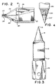
- a broken bolt stud B is trapped within a threaded bore in a support surface S.
- the stud is threaded in a first direction and has a predrilled hole H, permitting engagement of the extractor of the present invention for conveniently and easily removing the bolt without going through a series of cumbersome and inefficient preparatory steps.
- the bolt extractor 10 is formed with a cylindrical body 12 having a drive head 14 integrally formed at one end thereof.
- the drive head 14 preferably is hexagonal in shape to cooperate with suitable hand wrench or handle suitable for hole 15 or power tool drive means, or a threaded hole 30 into which a slide hammer or similar tool can be installed.
- the opposite end of the cylindrical body 12 is formed with a conical expander 16 which tapers to a point 19.
- the exterior of the cylindrical body 12 is provided with threads 17, formed in a second opposite direction to the threads on the stud, to threadedly receive an expander collet 18 as shown.
- the collet 18 has a series of internal threads 22 which are the same size and direction as the threads 17 on the cylindrical body for cooperation therewith.
- a plurality of resilient members 24 extend downwardly and inwardly from an annular ring 20 formed on one end of the expander collet 18 terminating in gripping fingers 26 which are resiliently held together due to the spring like action of the resilient members 24.
- the resilient members 24 are formed with an inner conical surface 23 and an outer conical surface 25, and are separated by a plurality of slots 27.
- the exterior surfaces of the fingers 26 are roughened with sharp edges or knurls to increase their gripping action.
- the expansion fingers lie parallel to a longitudinal line through the tapered conical expander 16.
- the outer surfaces 28 of the collet 18 are preferably formed with a hexagonal shape to permit independent rotation control and gripping by hand or a suitable tool.
- the outside diameter of the gripping fingers 26 is significantly less than both the cylindrical body 12 and the expander collet 18. This permits the extractor 10 to be used to remove relatively smaller bolt studs while using a large drive tool. It will be appreciated that the only limitation on the force used to operate the tool is the maximum shear stress that can be tolerated between the fingers 26 and the resilient members 24.
- the threaded connection between the collet 18 and the cylindrical body 12 permits rotation therebetween, causing the cylindrical body 12 to move longitudinally relative to the collet 18.
- the predrilled hole H is of sufficient diameter to permit insertion of the gripping fingers therein when the fingers are in a non-expanded position.
- a suitable hand or power drive tool is connected to the drive head 14. Alternately, a slide hammer (not shown) or other similar tool may be connected into the threaded hole 30.
- the shape of the conical expander 16 permits it to contact the upper edges of the resilient gripping fingers 26 directly, without having to engage the inner conical surface 23 of the resilient members 24. As the members 24 move apart, the resilient fingers 26 engage the interior of the hole H in the bolt stud B until a firm grip is formed. Continued rotation of the extractor 10 in the same stud removal direction causes a firmer grip by the fingers and all parts move together as a unit because of the frictional force holding them. This results in the unscrewing and removal of the bolt stud B.
- Figure 4 shows a detail of an embodiment of an extractor 200 including a cylindrical body 212 and an expander 216 formed with a point 217 which is rotatable with respect to the base of the expander 216.
Landscapes
- Engineering & Computer Science (AREA)
- Mechanical Engineering (AREA)
- Hand Tools For Fitting Together And Separating, Or Other Hand Tools (AREA)
- Automatic Assembly (AREA)
- Gripping Jigs, Holding Jigs, And Positioning Jigs (AREA)
- Dental Tools And Instruments Or Auxiliary Dental Instruments (AREA)
- Pharmaceuticals Containing Other Organic And Inorganic Compounds (AREA)
Claims (13)
- Extracteur (10) pour retirer d'un alésage taraudé une tige filetée cassée (B), la tige renfermant un trou pré-percé (H) destiné à venir en prise avec l'extracteur, comprenant :des première (12) et seconde (18) pièces attachées par vissage, coopérantes et mobiles l'une par rapport à l'autre ;ladite première pièce comprenant une tête motrice (14) à une de ses extrémités et un corps cylindrique intermédiaire (12) ;ledit corps cylindrique intermédiaire (12) étant formé de premiers filets (17) sur sa surface extérieure ;une seconde pièce comprenant une pince cylindrique (18) avec des seconds filets (22) sur une surface intérieure de celle-ci ; lesdits filets coopérant avec les filets dudit corps cylindrique, de telle sorte que ladite pince est fixée par vissage sur la surface extérieure dudit corps cylindrique ; ladite pince comprenant des moyens de préhension extensibles (24) formés d'un seul tenant avec une extrémité de ladite pince ; dans lequel lesdits moyens de préhension extensibles sont formés d'au moins une paire d'éléments de préhension résilients (24) inclinés vers le bas et vers l'intérieur à partir de ladite pince et se terminant par des doigts de préhension (26), lesdits doigts de préhension ayant des surfaces de préhension pour accrocher l'intérieur du trou pré-percé (H) de la tige filetée cassée ; caractérisé en ce que :la première pièce comprenant en outre un mandrin extensible conique (16) sur l'extrémité opposée à la tête motrice de celle-ci ;ledit mandrin extensible conique étant défini par une surface conique allongée qui est effilée en continu pour former une pointe (19) opposée à la tête motrice ;lesdits éléments de préhension résilients ayant chacun une surface conique intérieure (23) inclinée vers le bas et vers l'intérieur formant un premier angle allant de ladite pince (18) audit doigt de préhension ; et une forme extérieure cylindrique ;lesdits premier (17) et second (22) filets étant dans la direction opposée aux filets de la tige filetée cassée (B), de telle sorte qu'en exerçant une force sur ladite tête motrice (14) et en faisant tourner ledit corps cylindrique dans une direction pour retirer la tige filetée cassée cela provoque le déplacement longitudinal dudit mandrin extensible conique (16) et ladite pointe (19) dudit mandrin extensible conique passe entre lesdits moyens de préhension extensibles (24) jusqu'à ce que la rotation continue dudit corps cylindrique (12) amène ledit mandrin extensible conique (16) à étendre lesdits moyens de préhension extensibles (24) pour accrocher ladite tige filetée cassée, moyennant quoi la rotation continue de l'extracteur retire la tige filetée cassée (B) ;le mandrin extensible conique (16) s'effile vers l'intérieur jusqu'à une pointe formant un second angle ; et ledit premier angle de ladite surface conique intérieure (23) desdits moyens de préhension (24) est plus grand que ledit second angle.
- Extracteur (10) selon la revendication 1, dans lequel lesdites surfaces de préhension sur lesdits doigts de préhension (26) sont caractérisées par une surface irrégulière ayant une pluralité d'arêtes vives pour faciliter la préhension.
- Extracteur (10) selon la revendication 2, dans lequel lesdites surfaces de préhension sont moletées.
- Extracteur (10) selon la revendication 1, dans lequel ladite tête motrice (14) comprend des moyens de connexion d'un outil moteur auxiliaire afin d'imprimer une force motrice à ladite tête motrice.
- Extracteur (10) selon la revendication 4, dans lequel lesdits moyens sont une ouverture taraudée.
- Extracteur (10) selon la revendication 1, dans lequel les doigts de préhension résilients (24) ont un diamètre plus petit que ladite pince.
- Extracteur (10) selon la revendication 1, dans lequel les doigts de préhension résilients (24) ont un diamètre plus petit que ledit corps cylindrique intermédiaire (12).
- Extracteur (10) selon la revendication 1, dans lequel lesdits éléments de préhension résilients (24) desdits doigts de préhension sont séparés par des encoches (27).
- Extracteur (10) selon la revendication 8, dans lequel lesdites encoches (27) se terminent par un trou percé pour une flexibilité accrue.
- Extracteur (10) selon la revendication 1, dans lequel ladite tête motrice (14) comprend des moyens pour la connexion à un outil moteur auxiliaire afin d'imprimer une force motrice de rotation audit extracteur.
- Extracteur (10) selon la revendication 1, dans lequel ladite tête motrice (14) comprend des moyens pour la connexion à un outil moteur auxiliaire afin d'imprimer une force motrice de martelage à ladite tête motrice.
- Extracteur (10) selon la revendication 11, dans lequel lesdits moyens de connexion (15) sont une ouverture taraudée formée dans une extrémité de ladite tête motrice.
- Extracteur (10) selon la revendication 1, dans lequel lesdits doigts de préhension résilients (26) sont décalés longitudinalement par rapport à une extrémité de ladite pince (18) ; lesdits doigts étant en outre caractérisés par un diamètre sensiblement inférieur au diamètre de ladite pince et au diamètre dudit corps cylindrique intermédiaire (12) sur lequel ladite pince est mise en prise par vissage.
Applications Claiming Priority (3)
| Application Number | Priority Date | Filing Date | Title |
|---|---|---|---|
| US70551591A | 1991-05-24 | 1991-05-24 | |
| US07/913,065 US5279187A (en) | 1991-05-24 | 1992-07-14 | Expandable jaw broken bolt extractor |
| PCT/US1994/000135 WO1995018700A1 (fr) | 1991-05-24 | 1994-01-07 | Extracteur a machoire extensible pour boulons casses |
Publications (3)
| Publication Number | Publication Date |
|---|---|
| EP0737122A1 EP0737122A1 (fr) | 1996-10-16 |
| EP0737122A4 EP0737122A4 (fr) | 1997-03-26 |
| EP0737122B1 true EP0737122B1 (fr) | 2002-07-31 |
Family
ID=27377606
Family Applications (1)
| Application Number | Title | Priority Date | Filing Date |
|---|---|---|---|
| EP94909431A Expired - Lifetime EP0737122B1 (fr) | 1991-05-24 | 1994-01-07 | Extracteur a machoire extensible pour boulons casses |
Country Status (9)
| Country | Link |
|---|---|
| US (1) | US5279187A (fr) |
| EP (1) | EP0737122B1 (fr) |
| JP (1) | JP3550400B2 (fr) |
| AT (1) | ATE221432T1 (fr) |
| AU (1) | AU707386B2 (fr) |
| CA (1) | CA2180646C (fr) |
| DE (1) | DE69431124T2 (fr) |
| ES (1) | ES2181713T3 (fr) |
| WO (1) | WO1995018700A1 (fr) |
Families Citing this family (20)
| Publication number | Priority date | Publication date | Assignee | Title |
|---|---|---|---|---|
| US5906146A (en) * | 1997-08-21 | 1999-05-25 | Micron Technology, Inc. | Apparatus and method for extracting broken threaded members |
| US6501641B1 (en) * | 1998-10-23 | 2002-12-31 | Lg. Philips Lcd Co. Ltd. | Portable computer having a flat panel display device |
| US6286401B1 (en) * | 2000-06-08 | 2001-09-11 | Mohammed Ali Hajianpour | Screwdriver with holding feature for socket head screws |
| US6679196B1 (en) * | 2002-08-01 | 2004-01-20 | C J Wildbird Foods Limited | Bird feeding accessory with a collet |
| US20090240256A1 (en) * | 2008-03-19 | 2009-09-24 | Biomet Manufacturing Corp. | Method And Apparatus For Implanting an Augment |
| TW201119801A (en) * | 2009-12-08 | 2011-06-16 | New Way Tools Co Ltd | Screw remover. |
| US9612265B1 (en) | 2011-09-23 | 2017-04-04 | Cypress Semiconductor Corporation | Methods and apparatus to detect a conductive object |
| US20130150864A1 (en) * | 2011-12-12 | 2013-06-13 | Warsaw Orthopedic, Inc. | Surgical instrument and method |
| US20140102265A1 (en) * | 2012-10-13 | 2014-04-17 | Devin Lee Looijen | Expandable drivers and bits |
| JP6398923B2 (ja) * | 2015-08-26 | 2018-10-03 | Mkt株式会社 | 折損または損傷ボルトの除去用工具 |
| JP2017159438A (ja) * | 2016-03-09 | 2017-09-14 | Mkt株式会社 | 折損または損傷ボルトの除去用工具 |
| USD900893S1 (en) * | 2016-03-15 | 2020-11-03 | Brad A. English | Jagged tooth head fastener removal device for dirty environments |
| US12403574B2 (en) * | 2016-04-27 | 2025-09-02 | Grip Holdings Llc | Fastener extractor device |
| USD885149S1 (en) * | 2017-04-27 | 2020-05-26 | Grip Holdings Llc | Fastener extractor device |
| CN107738225A (zh) * | 2017-10-10 | 2018-02-27 | 浙江水利水电学院 | 水龙头、三角阀断丝取出装置及使用方法 |
| US20220054168A1 (en) * | 2020-08-19 | 2022-02-24 | Conmed Corporation | Driver for arthroscopic implant |
| USD953138S1 (en) * | 2020-12-18 | 2022-05-31 | Apex Brands, Inc. | Bolt extractor |
| USD953137S1 (en) * | 2020-12-18 | 2022-05-31 | Apex Brands, Inc. | Bolt extractor |
| JP7749210B2 (ja) * | 2021-08-18 | 2025-10-06 | 悦雄 市原 | ボルト外し工具及びボルト外し工具の使用方法 |
| USD1095195S1 (en) * | 2024-02-12 | 2025-09-30 | United States Of America As Represented By The Secretary Of The Air Force | Adapter for power tools |
Family Cites Families (11)
| Publication number | Priority date | Publication date | Assignee | Title |
|---|---|---|---|---|
| US1592987A (en) * | 1925-08-17 | 1926-07-20 | Bruce A Mayer | Dental tool |
| US1608364A (en) * | 1925-08-18 | 1926-11-23 | Fred E Bowman | Inside pipe wrench and nipple chuck |
| US2233232A (en) * | 1938-06-03 | 1941-02-25 | Crane Packing Co | Internal gripping device for smooth bore ferrules |
| US2721492A (en) * | 1953-09-14 | 1955-10-25 | Prevost Ernest Arthur | Lamp base extractor with resilient jaws |
| US2811067A (en) * | 1955-10-20 | 1957-10-29 | James B Greer | Internal expanding pipe wrench |
| FR1384457A (fr) * | 1964-03-03 | 1965-01-04 | Tournevis pour vis à tête creuse | |
| US3807028A (en) * | 1972-10-13 | 1974-04-30 | Itt | Insert mounting tool and method of using same |
| US3902384A (en) * | 1974-02-14 | 1975-09-02 | Augerscope Inc | Internal pipe wrench |
| US4513643A (en) * | 1982-03-24 | 1985-04-30 | Titan Tool Company | Automatic stud driving tool |
| AU7062087A (en) * | 1986-05-09 | 1987-11-12 | Polonsky, E. | Removing broken threaded fasteners |
| US5031487A (en) * | 1989-11-02 | 1991-07-16 | Alden Corporation | Broken bolt extractor |
-
1992
- 1992-07-14 US US07/913,065 patent/US5279187A/en not_active Expired - Lifetime
-
1994
- 1994-01-07 AT AT94909431T patent/ATE221432T1/de not_active IP Right Cessation
- 1994-01-07 ES ES94909431T patent/ES2181713T3/es not_active Expired - Lifetime
- 1994-01-07 JP JP51844595A patent/JP3550400B2/ja not_active Expired - Fee Related
- 1994-01-07 AU AU62277/94A patent/AU707386B2/en not_active Ceased
- 1994-01-07 WO PCT/US1994/000135 patent/WO1995018700A1/fr not_active Ceased
- 1994-01-07 DE DE69431124T patent/DE69431124T2/de not_active Expired - Fee Related
- 1994-01-07 CA CA002180646A patent/CA2180646C/fr not_active Expired - Fee Related
- 1994-01-07 EP EP94909431A patent/EP0737122B1/fr not_active Expired - Lifetime
Also Published As
| Publication number | Publication date |
|---|---|
| JP3550400B2 (ja) | 2004-08-04 |
| AU6227794A (en) | 1995-08-01 |
| DE69431124D1 (de) | 2002-09-05 |
| JPH09507171A (ja) | 1997-07-22 |
| US5279187A (en) | 1994-01-18 |
| CA2180646A1 (fr) | 1995-07-13 |
| EP0737122A1 (fr) | 1996-10-16 |
| ATE221432T1 (de) | 2002-08-15 |
| EP0737122A4 (fr) | 1997-03-26 |
| CA2180646C (fr) | 2002-02-05 |
| WO1995018700A1 (fr) | 1995-07-13 |
| ES2181713T3 (es) | 2003-03-01 |
| DE69431124T2 (de) | 2002-11-21 |
| AU707386B2 (en) | 1999-07-08 |
Similar Documents
| Publication | Publication Date | Title |
|---|---|---|
| AU707386B2 (en) | Expandable jaw broken bolt extractor | |
| US4777850A (en) | Drill-out threaded broken bolt extractor | |
| US5031487A (en) | Broken bolt extractor | |
| US11154969B2 (en) | Fastener extractor device | |
| US3735650A (en) | Extractor tool | |
| EP3814060B1 (fr) | Dispositif extracteur d'éléments de fixation | |
| US6978697B2 (en) | Damaged bolt and screw removing devices | |
| US5123310A (en) | Socket for turning fastener heads having deformed head surfaces | |
| US11787023B2 (en) | Male fastener extractor device | |
| US11590637B2 (en) | Methods and apparatuses for extracting and dislodging fasteners | |
| US5664467A (en) | Adjustable socket | |
| US4084457A (en) | Screw removing tool | |
| US3102447A (en) | Plastic screw type temporary fastener for anchor type nut plate or the like | |
| US5906146A (en) | Apparatus and method for extracting broken threaded members | |
| US4553455A (en) | Nut starter with special blades | |
| IL106328A (en) | Removes broken screws with expandable forceps | |
| US20030093081A1 (en) | Interference fit screw driver | |
| EP0322490B1 (fr) | Outil pour enlever un moyen de fixation fileté | |
| EP0588671A1 (fr) | Dispositif de fixation en plastique | |
| EP2364816A2 (fr) | Boulon extracteur | |
| GB2556106A (en) | A device and method for the removal of wall plugs | |
| JP2026012948A (ja) | ファスナーの引き抜きと取り外しの方法および器具 |
Legal Events
| Date | Code | Title | Description |
|---|---|---|---|
| PUAI | Public reference made under article 153(3) epc to a published international application that has entered the european phase |
Free format text: ORIGINAL CODE: 0009012 |
|
| 17P | Request for examination filed |
Effective date: 19960718 |
|
| AK | Designated contracting states |
Kind code of ref document: A1 Designated state(s): AT DE ES FR GB IT NL SE |
|
| A4 | Supplementary search report drawn up and despatched |
Effective date: 19970206 |
|
| AK | Designated contracting states |
Kind code of ref document: A4 Designated state(s): AT DE ES FR GB IT NL SE |
|
| 17Q | First examination report despatched |
Effective date: 20000403 |
|
| GRAG | Despatch of communication of intention to grant |
Free format text: ORIGINAL CODE: EPIDOS AGRA |
|
| GRAG | Despatch of communication of intention to grant |
Free format text: ORIGINAL CODE: EPIDOS AGRA |
|
| GRAH | Despatch of communication of intention to grant a patent |
Free format text: ORIGINAL CODE: EPIDOS IGRA |
|
| GRAH | Despatch of communication of intention to grant a patent |
Free format text: ORIGINAL CODE: EPIDOS IGRA |
|
| GRAA | (expected) grant |
Free format text: ORIGINAL CODE: 0009210 |
|
| AK | Designated contracting states |
Kind code of ref document: B1 Designated state(s): AT DE ES FR GB IT NL SE |
|
| REF | Corresponds to: |
Ref document number: 221432 Country of ref document: AT Date of ref document: 20020815 Kind code of ref document: T |
|
| REG | Reference to a national code |
Ref country code: GB Ref legal event code: FG4D |
|
| REF | Corresponds to: |
Ref document number: 69431124 Country of ref document: DE Date of ref document: 20020905 |
|
| ET | Fr: translation filed | ||
| PGFP | Annual fee paid to national office [announced via postgrant information from national office to epo] |
Ref country code: AT Payment date: 20030113 Year of fee payment: 10 |
|
| PGFP | Annual fee paid to national office [announced via postgrant information from national office to epo] |
Ref country code: SE Payment date: 20030128 Year of fee payment: 10 Ref country code: FR Payment date: 20030128 Year of fee payment: 10 |
|
| PGFP | Annual fee paid to national office [announced via postgrant information from national office to epo] |
Ref country code: NL Payment date: 20030130 Year of fee payment: 10 |
|
| PGFP | Annual fee paid to national office [announced via postgrant information from national office to epo] |
Ref country code: ES Payment date: 20030226 Year of fee payment: 10 |
|
| REG | Reference to a national code |
Ref country code: ES Ref legal event code: FG2A Ref document number: 2181713 Country of ref document: ES Kind code of ref document: T3 |
|
| PLBE | No opposition filed within time limit |
Free format text: ORIGINAL CODE: 0009261 |
|
| STAA | Information on the status of an ep patent application or granted ep patent |
Free format text: STATUS: NO OPPOSITION FILED WITHIN TIME LIMIT |
|
| 26N | No opposition filed |
Effective date: 20030506 |
|
| PG25 | Lapsed in a contracting state [announced via postgrant information from national office to epo] |
Ref country code: AT Free format text: LAPSE BECAUSE OF NON-PAYMENT OF DUE FEES Effective date: 20040107 |
|
| PG25 | Lapsed in a contracting state [announced via postgrant information from national office to epo] |
Ref country code: SE Free format text: LAPSE BECAUSE OF NON-PAYMENT OF DUE FEES Effective date: 20040108 Ref country code: ES Free format text: LAPSE BECAUSE OF NON-PAYMENT OF DUE FEES Effective date: 20040108 |
|
| PG25 | Lapsed in a contracting state [announced via postgrant information from national office to epo] |
Ref country code: NL Free format text: LAPSE BECAUSE OF NON-PAYMENT OF DUE FEES Effective date: 20040801 |
|
| EUG | Se: european patent has lapsed | ||
| PG25 | Lapsed in a contracting state [announced via postgrant information from national office to epo] |
Ref country code: FR Free format text: LAPSE BECAUSE OF NON-PAYMENT OF DUE FEES Effective date: 20040930 |
|
| NLV4 | Nl: lapsed or anulled due to non-payment of the annual fee |
Effective date: 20040801 |
|
| REG | Reference to a national code |
Ref country code: FR Ref legal event code: ST |
|
| PG25 | Lapsed in a contracting state [announced via postgrant information from national office to epo] |
Ref country code: IT Free format text: LAPSE BECAUSE OF NON-PAYMENT OF DUE FEES;WARNING: LAPSES OF ITALIAN PATENTS WITH EFFECTIVE DATE BEFORE 2007 MAY HAVE OCCURRED AT ANY TIME BEFORE 2007. THE CORRECT EFFECTIVE DATE MAY BE DIFFERENT FROM THE ONE RECORDED. Effective date: 20050107 |
|
| REG | Reference to a national code |
Ref country code: ES Ref legal event code: FD2A Effective date: 20040108 |
|
| PGFP | Annual fee paid to national office [announced via postgrant information from national office to epo] |
Ref country code: DE Payment date: 20090102 Year of fee payment: 16 |
|
| PGFP | Annual fee paid to national office [announced via postgrant information from national office to epo] |
Ref country code: GB Payment date: 20100106 Year of fee payment: 17 |
|
| PG25 | Lapsed in a contracting state [announced via postgrant information from national office to epo] |
Ref country code: DE Free format text: LAPSE BECAUSE OF NON-PAYMENT OF DUE FEES Effective date: 20100803 |
|
| GBPC | Gb: european patent ceased through non-payment of renewal fee |
Effective date: 20110107 |
|
| PG25 | Lapsed in a contracting state [announced via postgrant information from national office to epo] |
Ref country code: GB Free format text: LAPSE BECAUSE OF NON-PAYMENT OF DUE FEES Effective date: 20110107 |