EP0737501B1 - Sieb - Google Patents
Sieb Download PDFInfo
- Publication number
- EP0737501B1 EP0737501B1 EP96105208A EP96105208A EP0737501B1 EP 0737501 B1 EP0737501 B1 EP 0737501B1 EP 96105208 A EP96105208 A EP 96105208A EP 96105208 A EP96105208 A EP 96105208A EP 0737501 B1 EP0737501 B1 EP 0737501B1
- Authority
- EP
- European Patent Office
- Prior art keywords
- filter
- closure member
- flange
- housing
- strainer
- Prior art date
- Legal status (The legal status is an assumption and is not a legal conclusion. Google has not performed a legal analysis and makes no representation as to the accuracy of the status listed.)
- Expired - Lifetime
Links
Images


Classifications
-
- B—PERFORMING OPERATIONS; TRANSPORTING
- B01—PHYSICAL OR CHEMICAL PROCESSES OR APPARATUS IN GENERAL
- B01D—SEPARATION
- B01D35/00—Filtering devices having features not specifically covered by groups B01D24/00 - B01D33/00, or for applications not specifically covered by groups B01D24/00 - B01D33/00; Auxiliary devices for filtration; Filter housing constructions
- B01D35/02—Filters adapted for location in special places, e.g. pipe-lines, pumps, stop-cocks
- B01D35/04—Plug, tap, or cock filters filtering elements mounted in or on a faucet
-
- B—PERFORMING OPERATIONS; TRANSPORTING
- B01—PHYSICAL OR CHEMICAL PROCESSES OR APPARATUS IN GENERAL
- B01D—SEPARATION
- B01D35/00—Filtering devices having features not specifically covered by groups B01D24/00 - B01D33/00, or for applications not specifically covered by groups B01D24/00 - B01D33/00; Auxiliary devices for filtration; Filter housing constructions
- B01D35/02—Filters adapted for location in special places, e.g. pipe-lines, pumps, stop-cocks
-
- B—PERFORMING OPERATIONS; TRANSPORTING
- B01—PHYSICAL OR CHEMICAL PROCESSES OR APPARATUS IN GENERAL
- B01D—SEPARATION
- B01D29/00—Filters with filtering elements stationary during filtration, e.g. pressure or suction filters, not covered by groups B01D24/00 - B01D27/00; Filtering elements therefor
- B01D29/01—Filters with filtering elements stationary during filtration, e.g. pressure or suction filters, not covered by groups B01D24/00 - B01D27/00; Filtering elements therefor with flat filtering elements
-
- B—PERFORMING OPERATIONS; TRANSPORTING
- B01—PHYSICAL OR CHEMICAL PROCESSES OR APPARATUS IN GENERAL
- B01D—SEPARATION
- B01D29/00—Filters with filtering elements stationary during filtration, e.g. pressure or suction filters, not covered by groups B01D24/00 - B01D27/00; Filtering elements therefor
- B01D29/88—Filters with filtering elements stationary during filtration, e.g. pressure or suction filters, not covered by groups B01D24/00 - B01D27/00; Filtering elements therefor having feed or discharge devices
- B01D29/90—Filters with filtering elements stationary during filtration, e.g. pressure or suction filters, not covered by groups B01D24/00 - B01D27/00; Filtering elements therefor having feed or discharge devices for feeding
-
- B—PERFORMING OPERATIONS; TRANSPORTING
- B01—PHYSICAL OR CHEMICAL PROCESSES OR APPARATUS IN GENERAL
- B01D—SEPARATION
- B01D29/00—Filters with filtering elements stationary during filtration, e.g. pressure or suction filters, not covered by groups B01D24/00 - B01D27/00; Filtering elements therefor
- B01D29/96—Filters with filtering elements stationary during filtration, e.g. pressure or suction filters, not covered by groups B01D24/00 - B01D27/00; Filtering elements therefor in which the filtering elements are moved between filtering operations; Particular measures for removing or replacing the filtering elements; Transport systems for filters
Definitions
- the present invention relates to a strainer according to the preamble of claim 1.
- a strainer is known from DE 54896 C of May 28, 1890.
- This invention relates to a strainer mounted in a liquid flow passage for filtering liquids flowing through the passage.
- An automatic photographic developing machine develops photosensitive materials by passing them through treating tanks filled with various treating solutions such as developing, bleaching, fixing, stabilizing solutions.
- Replenishing tanks are connected to the respective treating tanks through supply pipes to refill them with solutions by activating pumps connected to the supply pipes.
- a strainer is usually provided in a pipe line connected to the inlet of each supply pipe to filter the treating solution before feeding it into the treating tank.
- Such a conventional strainer is mounted in the supply pipe at its portion connected to the inlet of the pump. In order to remove the filter of such a strainer, the entire strainer has to be dismounted from the pump after disconnecting the supply pipe.
- An object of this invention is to provide a strainer which permits easy cleaning or replacement of its filter.
- the knob By turning the knob, it is possible to turn the closure member to selectively open and close the inlet and outlet formed in the housing.
- the flange of the filter aligns with the cutouts.
- the filter can be removed for cleaning or replacement from the housing by pulling the knob, while preventing leakage of the fluid in the pipe.
- Fig. 1 shows a treating solution replenishing device for use in an automatic developing machine for developing photosensitive materials.
- a treating tank 1 is connected with a replenishing tank 2 via a supply pipe 3.
- a pump 4 provided in the supply pipe 3
- the treating solution in the replenishing tank 2 is fed into the treating tank 1.
- a strainer 10 according to this invention is provided in a pipe section 3a connected to the inlet of the pump 4.
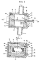
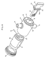
- Figs. 2 through 6 show the details of the strainer 10. It includes a housing 11 having a cylindrical bore 12 and an inlet 13 and an outlet 14 opening to the bore 12 on opposite sides of the bore.
- the bore 12 has an opening at one end of the housing 11 into which is screwed a cap 15.
- the housing 11 has an end plate 16 formed with a circular hole 17. Cutouts 18 are formed along the edge of the hole 17 (Fig. 4), diametrically opposite to each other. A rib 19 in the shape of a circular arc is formed on the outer surface of the end plate 16 (Fig. 6).
- a closure member 20 is mounted in the bore 12 of the housing 11. It has a passage 21 through which the inlet 13 communicates with the outlet 14, and a flat rectangular filter housing hole 22 that intersects the passage 21 and opens at one end of the closure member 20.
- a flange-receiving recess 23 is formed in one end of the closure member 20.
- a filter 24 is inserted in the hole 22 with its flange 25 received in the recess 23 so that its packing 25a is sandwiched between the flange 25 and the bottom of the recess 23.
- the flange 25 has to be so small that it can pass through the cutouts 18.
- a knob 26 provided on the outer side of the flange 25 protrudes outwardly through the circular hole 17 of the housing 11.
- the knob 26 has a protrusion 27 spaced from the flange 25 by a distance equal to the thickness of the end plate 16 of the housing 11 (Fig. 3).
- the protrusion 27 can abut both ends of the rib 19.
- the passage 21 of the closure member 20 is so positioned that the inlet 13 communicates with the outlet 14 through the passage 21.
- Fig. 3 shows the state in which the inlet 13 and the outlet 14 communicate with each other through the passage 21. In this state, the edge of the circular hole 17 is sandwiched between the flange 25 of the filter 24 and the protrusion 27. The filter 24 is thus unable to come out of the housing.
- the treating solution in the replenishing tank 2 will flow through the supply pipe 3.
- the filter 24 By passing through the filter 24, the treating solution is filtered. The thus filtered treating solution is fed into the treating tank 1.
- the filter 24 When the filter 24 is clogged and the filtering efficiency drops, the filter 24 is removed while the pump is inoperative to clean it or replace it with a new one.
- the filter 24 can be removed by turning the knob 26 until its protrusion 27 abuts the other end of the rib 19.
- the cleaned filter 24 or a new filter 24 is inserted through the circular hole 17 into the bore 22 until the flange 25 of the filter 24 is received in the recess 23. Then, the knob 26 is turned until the protrusion 27 of the knob 26 abuts the one end of the rib 19.
- the passage 21 in the closure member 20 moves to the position where it communicates with both the inlet 13 and the outlet 14. That is, the inlet 13 and the outlet 14 communicate with each other.
- the edge of the circular hole 17 is disposed between the flange 25 and the protrusion 27 as shown in Fig. 3, so that the filter 24 can be retained in the bore 22.
- the flange-receiving recess 23 is formed in one end of the closure member 20. But instead of this recess 23, a gap of a size corresponding to the thickness of the flange 25 may be provided between the end of the closure member 20 and the inner surface of the end plate 16 of the housing 11.
- strainer according to the present invention may be used not only in a treating solution replenishing device as in the embodiment, but for other devices or purposes.
Landscapes
- Chemical & Material Sciences (AREA)
- Chemical Kinetics & Catalysis (AREA)
- Engineering & Computer Science (AREA)
- Water Supply & Treatment (AREA)
- Filtration Of Liquid (AREA)
- Lubrication Details And Ventilation Of Internal Combustion Engines (AREA)
Claims (3)
- Ein Filter (10) mit einem Gehäuse (11), welches eine periphere Wand hat, die eine Ausnehmung (12) festlegt und an dem Fluideinlass (13) und dem Auslass (14) ausgebildet ist, einem Verschlussteil (20), welches drehbar in der Ausnehmung (12) des Gehäuses (11) montiert ist und mit einen Durchgang (21), durch welchen der Einlass (13) mit dem Auslass (14) kommuniziert, und einem Filtermontageloch (22) versehen ist, welches den Durchgang (21) kreuzt und das eine Öffnung an einem Ende des Verschlussteiles (20) aufweist, einem Filterelement (24), der entnehmbar in dem Filtermontageloch (22) eingeführt ist und einem Knopf (26), der das Gehäuse (11) überragt, wenn das Filterelement (24) in der Ausnehmung (12) befindlich ist, wobei der Knopf (26) einen Vorsprung (27) hat, der das Gehäuse (11, 25) überragt, und mit Mitteln (19), die eine Drehung des Verschlussteils (20) lediglich zwischen einer ersten Stellung, in der der Einlass (13) mit dem Auslass (14) durch den Durchgang (21), der in dem Verschlussteil (20) ausgebildet ist, kommuniziert, und einer zweiten Stellung, in der der Einlass (13) und der Auslass (14) voneinander durch das Verschlussteil (20) getrennt sind und in der das Filterelement (24) aus dem Montageloch (22) durch Bewegung in axialer Richtung des Montageloches (22) in der zweiten Stellung entnehmbar ist,
dadurch gekennzeichnet, dass das Gehäuse (11) eine Endplatte (16) aufweist, die mit einem kreisrunden Loch (17) und einem Paar von Ausschnitten (18) an dem Rand des kreisförmigen Loches (17) versehen ist, welche sich diametral gegenüberliegen;
dass der Filter (24) einen Flansch (25) aufweist, der durch die Ausschnitte (18) hindurch passt;
dass der Vorsprung (27) des Knopfes (26) von dem Flansch (25) mit einem Abstand entfernt angeordnet ist, welcher ein wenig größer als die Dicke der Endplatte (16) des Gehäuses (11) ist;
dass der Flansch (25) des Filters (24) in der zweiten Stellung des Verschlussteils (20) fluchtend mit den Ausschnitten (18) angeordnet ist;
dass der Flansch (25) eine Dichtung (25a) aufweist, die zwischen dem Flansch (25) und dem Verschlussteil (20) geklemmt ist und
dass die Ränder des kreisförmigen Loches (17) in der ersten Stellung zwischen dem Flansch (25) des Filters (24) und dem Vorsprung (27) eingeklemmt ist. - Filter nach Anspruch 1, dadurch gekennzeichnet, dass die Ränder des Flansches (25) benachbart zu der Endplatte (16) abgeschrägt sind.
- Filter nach Anspruch 1 oder 2, dadurch gekennzeichnet, dass die Dichtung (25a) in einer Filtergehäuseausnehmung (23) aufgenommen ist, die an einem Ende des Verschlussteiles (22) ausgeformt ist.
Applications Claiming Priority (3)
| Application Number | Priority Date | Filing Date | Title |
|---|---|---|---|
| JP8534095 | 1995-04-11 | ||
| JP7085340A JP3047773B2 (ja) | 1995-04-11 | 1995-04-11 | ストレーナ |
| JP85340/95 | 1995-04-11 |
Publications (3)
| Publication Number | Publication Date |
|---|---|
| EP0737501A2 EP0737501A2 (de) | 1996-10-16 |
| EP0737501A3 EP0737501A3 (de) | 1997-11-26 |
| EP0737501B1 true EP0737501B1 (de) | 2002-07-17 |
Family
ID=13855931
Family Applications (1)
| Application Number | Title | Priority Date | Filing Date |
|---|---|---|---|
| EP96105208A Expired - Lifetime EP0737501B1 (de) | 1995-04-11 | 1996-04-01 | Sieb |
Country Status (7)
| Country | Link |
|---|---|
| US (1) | US5567310A (de) |
| EP (1) | EP0737501B1 (de) |
| JP (1) | JP3047773B2 (de) |
| KR (1) | KR100195461B1 (de) |
| CN (1) | CN1052169C (de) |
| CA (1) | CA2172594C (de) |
| DE (1) | DE69622309T2 (de) |
Families Citing this family (36)
| Publication number | Priority date | Publication date | Assignee | Title |
|---|---|---|---|---|
| GB2309063B (en) * | 1996-01-10 | 2000-02-23 | Gascon Prod Ltd | Improvements in or relating to valves |
| GB0026948D0 (en) | 2000-11-03 | 2000-12-20 | Eastman Kodak Co | Processing photographic material |
| US7052615B2 (en) * | 2002-12-10 | 2006-05-30 | King Technology | Dispensing system |
| JP4726638B2 (ja) * | 2006-01-19 | 2011-07-20 | 株式会社Roki | オイルストレーナ |
| JP2007192140A (ja) * | 2006-01-19 | 2007-08-02 | Toyo Roki Mfg Co Ltd | オイルストレーナ |
| USD655377S1 (en) | 2011-09-15 | 2012-03-06 | Whirlpool Corporation | Filter unit |
| USD654562S1 (en) | 2011-09-15 | 2012-02-21 | Whirlpool Corporation | Filter unit |
| US8580109B2 (en) | 2011-09-15 | 2013-11-12 | Whirlpool Corporation | Electronic interface for water filter system |
| USD654559S1 (en) | 2011-09-15 | 2012-02-21 | Whirlpool Corporation | Filter unit |
| USD654563S1 (en) | 2011-09-15 | 2012-02-21 | Whirlpool Corporation | Filter unit |
| US20130068684A1 (en) | 2011-09-15 | 2013-03-21 | Whirlpool Corporation | Filter unit |
| USD654561S1 (en) | 2011-09-15 | 2012-02-21 | Whirlpool Corporation | Filter unit |
| USD654566S1 (en) | 2011-09-15 | 2012-02-21 | Whirlpool Corporation | Filter unit |
| USD655378S1 (en) | 2011-09-15 | 2012-03-06 | Whirlpool Corporation | Filter unit |
| USD654564S1 (en) | 2011-09-15 | 2012-02-21 | Whirlpool Corporation | Filter unit |
| US8950052B2 (en) | 2011-09-15 | 2015-02-10 | Whirlpool Corporation | Method of installing a filter unit |
| USD654560S1 (en) | 2011-09-15 | 2012-02-21 | Whirlpool Corporation | Filter unit |
| USD654565S1 (en) | 2011-09-15 | 2012-02-21 | Whirlpool Corporation | Filter unit |
| US8591736B2 (en) | 2011-09-15 | 2013-11-26 | Whirlpool Corporation | Water filter unit |
| US8845896B2 (en) | 2011-09-15 | 2014-09-30 | Whirlpool Corporation | Water filter system |
| US8413818B1 (en) | 2011-09-15 | 2013-04-09 | Whirlpool Corporation | Filter unit |
| CN105499111A (zh) * | 2014-10-20 | 2016-04-20 | 航天长征化学工程股份有限公司 | 气化炉煤粉输送系统转动式过滤装置 |
| CN105586096B (zh) * | 2014-10-20 | 2018-08-17 | 航天长征化学工程股份有限公司 | 一种气化炉煤粉输送系统的直动式过滤装置 |
| GB2534854A (en) * | 2015-01-30 | 2016-08-10 | Caterpillar Sarl | Filter positioning system and method |
| WO2016179594A1 (en) * | 2015-05-07 | 2016-11-10 | Avitus Orthopaedics, Inc. | Systems and methods for bone and tissue harvesting |
| WO2017147258A1 (en) | 2016-02-23 | 2017-08-31 | Indiana University Research & Technology Corporation | Emapii neutralizing antibody limits influenza a virus (iav)-induced lung injury |
| GB2560721B (en) * | 2017-03-21 | 2021-01-06 | Bamford Excavators Ltd | An oil filter assembly |
| US10525387B2 (en) | 2017-04-06 | 2020-01-07 | Whirlpool Corporation | Filter cartridge |
| US10584040B2 (en) | 2017-10-06 | 2020-03-10 | Whirlpool Corporation | Filter cartridge |
| JP7101048B2 (ja) * | 2018-05-31 | 2022-07-14 | 株式会社Lixil | 水回り部品及び水回り装置 |
| CN108744696A (zh) * | 2018-06-28 | 2018-11-06 | 安徽天地高纯溶剂有限公司 | 一种用于高纯有机溶剂的电磁吸附装置 |
| US10807025B2 (en) | 2018-08-06 | 2020-10-20 | Whirlpool Corporation | Blind attachment interface for filter housing assembly |
| US11781693B2 (en) * | 2020-09-11 | 2023-10-10 | Yuan Mei Corp. | Pipe fittings with filter |
| CN112403059A (zh) * | 2020-10-20 | 2021-02-26 | 安徽高伟新材料科技有限公司 | 一种塑料片材挤出机中方便更换过滤网的过滤装置 |
| CN112546724A (zh) * | 2020-11-19 | 2021-03-26 | 太湖县牛镇兴利自来水厂 | 一种自来水厂废水过滤装置 |
| KR102559179B1 (ko) * | 2020-11-27 | 2023-07-25 | 한국가스공사 | 회전가능한 메쉬스크린을 구비한 양방향 스트레이너 |
Family Cites Families (10)
| Publication number | Priority date | Publication date | Assignee | Title |
|---|---|---|---|---|
| DE54896C (de) * | WlLH. HEIDELMANN in Stuttgart, Hauffstr. 3 | Zapfhahn mit Sieb | ||
| US2331119A (en) * | 1939-05-20 | 1943-10-05 | United Shoe Machinery Corp | Lubricating system |
| US3788484A (en) * | 1971-08-23 | 1974-01-29 | Coulter Electronics | Inline fluid filter |
| US3788487A (en) * | 1971-10-21 | 1974-01-29 | T Dawson | Container with cup liners and cup holders |
| US3715032A (en) * | 1971-11-03 | 1973-02-06 | S Nicko | Fluid treatment devices |
| SE432887B (sv) * | 1976-03-23 | 1984-04-30 | Rosaen Nils O | Vetskefiltreringsanordning |
| DE2824346C2 (de) * | 1978-06-02 | 1982-08-26 | Bosch-Siemens Hausgeräte GmbH, 7000 Stuttgart | Druckwasser-Anschlußarmatur in einer Wasch- oder Geschirrspülmaschine |
| SE7902710L (sv) * | 1979-03-27 | 1980-09-22 | Forsheda Gummifabrik Ab | Filteranordning |
| DE3435288A1 (de) * | 1984-09-26 | 1986-04-03 | Norbert 6635 Schwalbach Scherer | Schmutzfaenger mit beidseitiger absperrung |
| GB8729518D0 (en) * | 1987-12-18 | 1988-02-03 | Newteam Ltd | Liquid filter apparatus |
-
1995
- 1995-04-11 JP JP7085340A patent/JP3047773B2/ja not_active Expired - Fee Related
-
1996
- 1996-03-25 CA CA002172594A patent/CA2172594C/en not_active Expired - Fee Related
- 1996-03-26 US US08/621,940 patent/US5567310A/en not_active Expired - Lifetime
- 1996-03-29 KR KR1019960009087A patent/KR100195461B1/ko not_active Expired - Fee Related
- 1996-04-01 DE DE69622309T patent/DE69622309T2/de not_active Expired - Lifetime
- 1996-04-01 EP EP96105208A patent/EP0737501B1/de not_active Expired - Lifetime
- 1996-04-10 CN CN96108009A patent/CN1052169C/zh not_active Expired - Fee Related
Also Published As
| Publication number | Publication date |
|---|---|
| DE69622309T2 (de) | 2002-11-14 |
| EP0737501A2 (de) | 1996-10-16 |
| CA2172594C (en) | 2000-02-29 |
| KR960037090A (ko) | 1996-11-19 |
| KR100195461B1 (ko) | 1999-06-15 |
| DE69622309D1 (de) | 2002-08-22 |
| JP3047773B2 (ja) | 2000-06-05 |
| CN1144140A (zh) | 1997-03-05 |
| CA2172594A1 (en) | 1996-10-12 |
| EP0737501A3 (de) | 1997-11-26 |
| US5567310A (en) | 1996-10-22 |
| CN1052169C (zh) | 2000-05-10 |
| JPH08281024A (ja) | 1996-10-29 |
Similar Documents
| Publication | Publication Date | Title |
|---|---|---|
| EP0737501B1 (de) | Sieb | |
| EP1453585B1 (de) | Leckarme austauschbare wasserfilteranordnung | |
| US7387726B2 (en) | Liquid filter system | |
| CA2452324C (en) | Fluid filtration system including replaceable filter module | |
| EP0619070B1 (de) | Äussere Filtervorrichtung, insbesondere für Auqarien und Zierwasserbehälter | |
| JPH01199611A (ja) | 止め弁付フイルタ装置 | |
| EP0833197B1 (de) | Photographisches Entwicklungsgerät mit Filteranordnung | |
| US6322696B1 (en) | Inlet filter for high pressure sprayer | |
| US6241884B1 (en) | Liquid treatment cartridge | |
| JPH0910515A (ja) | 内燃機関用オイルフィルタ | |
| CN1226480A (zh) | 喷墨式打印机的替换流体容器的连接装置 | |
| US5693219A (en) | Apparatus for backwashing a water filter | |
| JPH0771404A (ja) | 作動油タンクのフィルタ装置 | |
| JP2677211B2 (ja) | 浄水器付き電気貯湯容器 | |
| EP0088759B1 (de) | Auslassmittel für einen behälter | |
| KR920006348Y1 (ko) | 스트레이너장치 | |
| KR19980086014A (ko) | 물분배기용 취수 구조 | |
| JP3310878B2 (ja) | 流量調節装置 | |
| US5690822A (en) | Water purifier having a storage tank and an excess water discharge conduit | |
| US5701540A (en) | Photographic processor and improved filter assembly | |
| JPH0215531Y2 (de) | ||
| JPH0647169Y2 (ja) | オイルストレーナ取付装置 | |
| KR19990003667A (ko) | 물통탑재 냉온수기의 정수장치 | |
| JP2591130Y2 (ja) | 浄水器 | |
| JPH10277330A (ja) | 新規なこし器 |
Legal Events
| Date | Code | Title | Description |
|---|---|---|---|
| PUAI | Public reference made under article 153(3) epc to a published international application that has entered the european phase |
Free format text: ORIGINAL CODE: 0009012 |
|
| AK | Designated contracting states |
Kind code of ref document: A2 Designated state(s): CH DE FR GB IT LI |
|
| 17P | Request for examination filed |
Effective date: 19961119 |
|
| PUAL | Search report despatched |
Free format text: ORIGINAL CODE: 0009013 |
|
| AK | Designated contracting states |
Kind code of ref document: A3 Designated state(s): CH DE FR GB IT LI |
|
| 17Q | First examination report despatched |
Effective date: 20000321 |
|
| GRAG | Despatch of communication of intention to grant |
Free format text: ORIGINAL CODE: EPIDOS AGRA |
|
| GRAG | Despatch of communication of intention to grant |
Free format text: ORIGINAL CODE: EPIDOS AGRA |
|
| GRAH | Despatch of communication of intention to grant a patent |
Free format text: ORIGINAL CODE: EPIDOS IGRA |
|
| GRAH | Despatch of communication of intention to grant a patent |
Free format text: ORIGINAL CODE: EPIDOS IGRA |
|
| GRAA | (expected) grant |
Free format text: ORIGINAL CODE: 0009210 |
|
| AK | Designated contracting states |
Kind code of ref document: B1 Designated state(s): CH DE FR GB IT LI |
|
| PG25 | Lapsed in a contracting state [announced via postgrant information from national office to epo] |
Ref country code: LI Free format text: LAPSE BECAUSE OF FAILURE TO SUBMIT A TRANSLATION OF THE DESCRIPTION OR TO PAY THE FEE WITHIN THE PRESCRIBED TIME-LIMIT Effective date: 20020717 Ref country code: IT Free format text: LAPSE BECAUSE OF FAILURE TO SUBMIT A TRANSLATION OF THE DESCRIPTION OR TO PAY THE FEE WITHIN THE PRE;WARNING: LAPSES OF ITALIAN PATENTS WITH EFFECTIVE DATE BEFORE 2007 MAY HAVE OCCURRED AT ANY TIME BEFORE 2007. THE CORRECT EFFECTIVE DATE MAY BE DIFFERENT FROM THE ONE RECORDED.SCRIBED TIME-LIMIT Effective date: 20020717 Ref country code: CH Free format text: LAPSE BECAUSE OF FAILURE TO SUBMIT A TRANSLATION OF THE DESCRIPTION OR TO PAY THE FEE WITHIN THE PRESCRIBED TIME-LIMIT Effective date: 20020717 |
|
| REG | Reference to a national code |
Ref country code: GB Ref legal event code: FG4D |
|
| REG | Reference to a national code |
Ref country code: CH Ref legal event code: EP |
|
| REF | Corresponds to: |
Ref document number: 69622309 Country of ref document: DE Date of ref document: 20020822 |
|
| ET | Fr: translation filed | ||
| REG | Reference to a national code |
Ref country code: CH Ref legal event code: PL |
|
| PLBE | No opposition filed within time limit |
Free format text: ORIGINAL CODE: 0009261 |
|
| STAA | Information on the status of an ep patent application or granted ep patent |
Free format text: STATUS: NO OPPOSITION FILED WITHIN TIME LIMIT |
|
| 26N | No opposition filed |
Effective date: 20030422 |
|
| PGFP | Annual fee paid to national office [announced via postgrant information from national office to epo] |
Ref country code: GB Payment date: 20050330 Year of fee payment: 10 |
|
| PGFP | Annual fee paid to national office [announced via postgrant information from national office to epo] |
Ref country code: FR Payment date: 20050408 Year of fee payment: 10 |
|
| PG25 | Lapsed in a contracting state [announced via postgrant information from national office to epo] |
Ref country code: GB Free format text: LAPSE BECAUSE OF NON-PAYMENT OF DUE FEES Effective date: 20060401 |
|
| GBPC | Gb: european patent ceased through non-payment of renewal fee |
Effective date: 20060401 |
|
| REG | Reference to a national code |
Ref country code: FR Ref legal event code: ST Effective date: 20061230 |
|
| PG25 | Lapsed in a contracting state [announced via postgrant information from national office to epo] |
Ref country code: FR Free format text: LAPSE BECAUSE OF NON-PAYMENT OF DUE FEES Effective date: 20060502 |
|
| PGFP | Annual fee paid to national office [announced via postgrant information from national office to epo] |
Ref country code: DE Payment date: 20100430 Year of fee payment: 15 |
|
| REG | Reference to a national code |
Ref country code: DE Ref legal event code: R119 Ref document number: 69622309 Country of ref document: DE |
|
| REG | Reference to a national code |
Ref country code: DE Ref legal event code: R119 Ref document number: 69622309 Country of ref document: DE |
|
| PG25 | Lapsed in a contracting state [announced via postgrant information from national office to epo] |
Ref country code: DE Free format text: LAPSE BECAUSE OF NON-PAYMENT OF DUE FEES Effective date: 20111031 |