EP0737551A2 - Vorrichtung zum Beheizen der Klingen von Scheren, Messern und dergleichen - Google Patents
Vorrichtung zum Beheizen der Klingen von Scheren, Messern und dergleichen Download PDFInfo
- Publication number
- EP0737551A2 EP0737551A2 EP96103732A EP96103732A EP0737551A2 EP 0737551 A2 EP0737551 A2 EP 0737551A2 EP 96103732 A EP96103732 A EP 96103732A EP 96103732 A EP96103732 A EP 96103732A EP 0737551 A2 EP0737551 A2 EP 0737551A2
- Authority
- EP
- European Patent Office
- Prior art keywords
- blade
- heating
- heating foil
- blades
- cover
- Prior art date
- Legal status (The legal status is an assumption and is not a legal conclusion. Google has not performed a legal analysis and makes no representation as to the accuracy of the status listed.)
- Granted
Links
Images
Classifications
-
- H—ELECTRICITY
- H05—ELECTRIC TECHNIQUES NOT OTHERWISE PROVIDED FOR
- H05B—ELECTRIC HEATING; ELECTRIC LIGHT SOURCES NOT OTHERWISE PROVIDED FOR; CIRCUIT ARRANGEMENTS FOR ELECTRIC LIGHT SOURCES, IN GENERAL
- H05B3/00—Ohmic-resistance heating
-
- A—HUMAN NECESSITIES
- A45—HAND OR TRAVELLING ARTICLES
- A45D—HAIRDRESSING OR SHAVING EQUIPMENT; EQUIPMENT FOR COSMETICS OR COSMETIC TREATMENTS, e.g. FOR MANICURING OR PEDICURING
- A45D26/00—Hair-singeing apparatus; Apparatus for removing superfluous hair, e.g. tweezers
- A45D26/0009—Hair-singeing apparatus; Apparatus for removing superfluous hair, e.g. tweezers by singeing
-
- B—PERFORMING OPERATIONS; TRANSPORTING
- B26—HAND CUTTING TOOLS; CUTTING; SEVERING
- B26B—HAND-HELD CUTTING TOOLS NOT OTHERWISE PROVIDED FOR
- B26B13/00—Hand shears; Scissors
- B26B13/06—Hand shears; Scissors characterised by the shape of the blades
-
- B—PERFORMING OPERATIONS; TRANSPORTING
- B26—HAND CUTTING TOOLS; CUTTING; SEVERING
- B26B—HAND-HELD CUTTING TOOLS NOT OTHERWISE PROVIDED FOR
- B26B9/00—Blades for hand knives
-
- B—PERFORMING OPERATIONS; TRANSPORTING
- B26—HAND CUTTING TOOLS; CUTTING; SEVERING
- B26D—CUTTING; DETAILS COMMON TO MACHINES FOR PERFORATING, PUNCHING, CUTTING-OUT, STAMPING-OUT OR SEVERING
- B26D7/00—Details of apparatus for cutting, cutting-out, stamping-out, punching, perforating, or severing by means other than cutting
- B26D7/08—Means for treating work or cutting member to facilitate cutting
- B26D7/10—Means for treating work or cutting member to facilitate cutting by heating
-
- H—ELECTRICITY
- H05—ELECTRIC TECHNIQUES NOT OTHERWISE PROVIDED FOR
- H05B—ELECTRIC HEATING; ELECTRIC LIGHT SOURCES NOT OTHERWISE PROVIDED FOR; CIRCUIT ARRANGEMENTS FOR ELECTRIC LIGHT SOURCES, IN GENERAL
- H05B3/00—Ohmic-resistance heating
- H05B3/20—Heating elements having extended surface area substantially in a two-dimensional [2D] plane, e.g. plate-heater
- H05B3/34—Heating elements having extended surface area substantially in a two-dimensional [2D] plane, e.g. plate-heater flexible, e.g. heating nets or webs
-
- H—ELECTRICITY
- H05—ELECTRIC TECHNIQUES NOT OTHERWISE PROVIDED FOR
- H05B—ELECTRIC HEATING; ELECTRIC LIGHT SOURCES NOT OTHERWISE PROVIDED FOR; CIRCUIT ARRANGEMENTS FOR ELECTRIC LIGHT SOURCES, IN GENERAL
- H05B2203/00—Aspects relating to Ohmic resistive heating covered by group H05B3/00
- H05B2203/013—Heaters using resistive films or coatings
-
- H—ELECTRICITY
- H05—ELECTRIC TECHNIQUES NOT OTHERWISE PROVIDED FOR
- H05B—ELECTRIC HEATING; ELECTRIC LIGHT SOURCES NOT OTHERWISE PROVIDED FOR; CIRCUIT ARRANGEMENTS FOR ELECTRIC LIGHT SOURCES, IN GENERAL
- H05B2203/00—Aspects relating to Ohmic resistive heating covered by group H05B3/00
- H05B2203/03—Heaters specially adapted for heating hand held tools
Definitions
- the invention relates to a device for heating scissors, knives and the like according to the preamble of claim 1.
- a pair of scissors for simultaneously cutting and cauterizing the hair is known from WO 92/00688.
- the blades have recesses into which a blade is inserted, on which the cutting edge is formed.
- An electrical heating foil is inserted into the recess, which is shielded from the metallic blade by thermal insulation. It is thereby achieved that the electric heating foil mainly heats the blade and the metallic blade is heated little.
- the electrical heating foils are connected in series as resistors, an electrical connection cable for the power supply being connected to one of the connecting ends of the heating foil, while the other ends of the heating foils are soldered to the respective blade and via the metallic blades and the metallic hinge pin connecting them are electrically connected together.
- the current supply to the heating foils is over controlled a temperature sensor which is inserted between the blade and the blade blade and detects the temperature of the blade blade.
- the heated blade blades these known scissors, enable the hair to be cut, the temperature of the blade blades from 150 ° C. to 300 ° C. simultaneously causing the hair tips to be cauterized. Because of the recesses in the blades and the blade blades used, complex, custom-made scissors are necessary. The current flow over the blades and the hinge pin makes it necessary to provide the blades with electrically insulating handle parts.
- the invention has for its object to provide a versatile device that is simple in construction and inexpensive to manufacture and is suitable for heating the blades of largely commercially available devices.
- the device according to the invention can be used in commercial devices, the blades of which are made of metal, e.g. B. with scissors for simultaneous cutting and cauterization of the hair, with thinning scissors, with razors, with blade knives, etc.
- the electrical heating module is applied outside to the outer surface of the blade.
- the outside the blade and the heating foil are covered by the plastic cover, so that the heating foil and the blade are both electrically and thermally insulated and there is no danger that live or hot parts are accidentally touched when using the device. Since the heating foil and the plastic part of the cover are only placed on the outside of the blades, equipping or retrofitting the device with the heating module is simple and inexpensive.
- the heating foil can be arranged on the outside of the blade so that its one longitudinal edge adjoins the cutting edge of the blade, the heating power of the heating foil being predominantly concentrated on the cutting edge side of the heating foil. This provides the opportunity to specifically heat the cutting edge of the blade.
- the heating foil extends from the tip of the blade along the cutting edge.
- the cover is preferably designed as a dimensionally stable shell which is adapted to the outer contour of the blade. The cover can be attached to the blade in a simple manner with two screws, the heating foil advantageously being clamped and fixed between the blade and the cover.
- the attachment of the cover and the heating film is preferably detachable, so that the cover and the heating film can be removed in a simple manner for cleaning and disinfecting the device.
- the simple attachment and detachability of the cover and the heating foil also make it possible to use the same heating module for different devices.
- the temperature sensor is optimally arranged in the area of greatest warming, so that a reliable function is guaranteed.
- the connecting lines for the heating foils and the temperature sensors are preferably guided along the handle part of the blade and fixed on this handle part.
- a strain relief part is expediently attached to this handle part, which covers and fixes the connecting lines. The connecting lines thus do not hinder the handling of the device and at the same time strain relief of the connections of the lines to the heating foils is ensured.
- the connecting lines of the heating foil and possibly the temperature sensor of the other handle part must be routed to this first handle part without impeding the pivoting movement of the scissors.
- the connecting lines can be led around the scissor part to the first handle part. Since this could possibly interfere with the outside of the connecting lines, the hinge pin connecting the two scissor parts is preferably designed as a hollow pin and the connecting lines of the second scissor part are guided in an isolated manner by this hollow hinge pin to the handle part of the first scissor part.
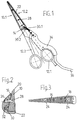
- the scissors consist of two scissor parts made of steel, each made in one piece from a blade 10.1 or 10.2 and a handle part 12.1 or 12.2.
- the scissor parts are pivotally connected to one another by means of a hinge pin 14 designed as a screw.
- the hinge pin 14 is coaxially pierced.
- An electrical heating foil 16 as shown in FIG. 3, is arranged on the outside of the blades 10.1 and 10.2.
- the heating film 16 consists of a plastic film with applied heating resistor tracks 18.
- the heating film 16 corresponds in shape essentially to the shape of the outer surface of the blades 10 and is arranged on this outer surface so that the heating film 16 extends from the tip of the blade 10 to close to the hinge pin 14 extends.
- the heating foil 16 adjoins the cutting edge 20 of the blade 10 with its one longitudinal edge. As a result, the heating power of the heating foil 16 is concentrated on the area of the cutting edge 20 of the blade 10.
- the cover 22 extends in the longitudinal direction over the length of the blade 10 up to close to the hinge pin 14.
- the cover 22 is in the cross-sectional profile angled so that it rests on the one hand on the outside of the blade 10 and on the other hand on the rear edge of the blade 10 opposite the cutting edge 20, as can be seen in FIG.
- the cover 22 completely covers this blade 10 and the heating foil 16 both in length and in width.
- the cover 22 completely covers the rear edge of the blade 10 opposite the cutting edge 20. Only the cutting edge 20 and the abutting inner surfaces of the blades 10.1 and 10.2 are left free from the cover 22.
- the blades 10.1 and 10.2 are drilled through at two points spaced apart in the longitudinal direction of the blade. These holes in the blades 10 correspond to position-matching holes 24 in the heating foil 16 and threaded holes 26 in the covers 22.
- the holes in the blades 10.1 and 10.2 are countersunk on their inner surface. From the inside of the blades 10, screws 28 are inserted into these bores, which penetrate the holes 24 in the heating foil 16 and are screwed into the threaded bores 26 of the cover 22.
- the heating foils 16 and the covers 22 are releasably attached to the blades 10.1 and 10.2, wherein the threaded bores 26 can preferably be formed as blind bores, so that the attachment to the outside of the cover 22 is not visible.
- a temperature sensor (not shown in the drawing) is embedded in the central region of the heating foil 16 in order to measure the temperature of the blade 10.
- Connection lines 30.1 and 30.2 are used to feed the heating foils 16.
- the connecting lines 30.1 of the heating foil 16 and the possibly associated temperature sensor emerge from the cover 22 of the blade 10.1 at the handle-side end and are guided along the handle part 12.1 of this scissor part.
- the connecting lines 30.2 of the heating foil of the other blade 10.2 and the possibly associated temperature sensor emerge from the cover 22 on the handle side, are passed through the axial bore of the hinge pin 14 in an insulated manner and then likewise run along the handle part 12.1 of the other scissor part.
- All connecting lines 30.1 and 30.2 are guided along the outside of the handle part 12.1 and fixed and covered there by a strain relief part 34.
- the strain relief part 34 is a plastic shell, which is pushed with a U-shaped profile from the outside over the grip part 12.1 and clamped there.
- the connecting lines 30.1 and 30.2 come together in a connecting cable 36 at the rear end of the strain relief part 34 and the handle part 12.1.
- the scissors are connected to a power supply and control unit via the connecting cable 36.
- the power supply of the heating foils 16 is regulated via the control unit in accordance with the temperature determined via the temperature sensors so that a temperature of the blades 10 specified in the control unit is maintained.
- the heating foil 16 brings about optimal heating of the blades 10, the heating region concentrating essentially on the cutting edge 20 of the blades 10.
- the covers 22 prevent the heating foils 16 and the heated areas of the blades 10 from being inadvertently touched.
Landscapes
- Life Sciences & Earth Sciences (AREA)
- Forests & Forestry (AREA)
- Engineering & Computer Science (AREA)
- Mechanical Engineering (AREA)
- Physics & Mathematics (AREA)
- Optics & Photonics (AREA)
- Scissors And Nippers (AREA)
- Details Of Cutting Devices (AREA)
- Surface Heating Bodies (AREA)
Abstract
Description
- Die Erfindung betrifft eine Vorrichtung zum Beheizen von Scheren, Messern und dergleichen gemäß dem Oberbegriff des Anspruchs 1.
- Aus der WO 92/00688 ist eine Schere zum gleichzeitigen Schneiden und Kauterisieren des Haares bekannt. Bei dieser Schere weisen die Klingen Ausnehmungen auf, in welche ein Klingenblatt eingesetzt wird, an welchem die Schneidkante ausgebildet ist. In die Ausnehmung wird eine elektrische Heizfolie eingelegt, die durch eine Wärmeisolierung gegen die metallische Klinge abgeschirmt ist. Dadurch wird erreicht, daß die elektrische Heizfolie vorwiegend das Klingenblatt beheizt und die metallische Klinge wenig erhitzt wird. Die elektrischen Heizfolien sind als Widerstände in Serie geschaltet, wobei jeweils an eines der Anschlußenden der Heizfolie ein elektrisches Anschlußkabel der Stromspeisung angeschlossen ist, während die jeweils anderen Enden der Heizfolien an die jeweilige Klinge angelötet sind und über die metallischen Klingen und den diese verbindenden metallischen Gelenkbolzen elektrisch leitend miteinander verbunden sind. Die Stromführung zu den Heizfolien wird über einen Temperaturfühler gesteuert, der zwischen die Klinge und das Klingenblatt eingesetzt ist und die Temperatur des Klingenblattes erfaßt.
- Die beheizten Klingenblätter, dieser bekannten Schere ermöglichen ein Schneiden des Haares, wobei die Temperatur der Klingenblätter von 150°C bis 300°C gleichzeitig ein Kauterisieren der Haarspitzen bewirkt. Wegen der Ausnehmungen der Klingen und der eingesetzten Klingenblätter ist eine aufwendige Sonderanfertigung der Schere notwendig. Die Stromführung über die Klingen und den Gelenkbolzen macht es notwendig die Klingen mit elektrisch isolierenden Griffteilen zu versehen.
- Der Erfindung liegt die Aufgabe zugrunde, eine vielseitig einsetzbare Vorrichtung zur Verfügung zu stellen, die im Aufbau einfach und in der Herstellung kostengünstig ist und sich zum Beheizen der Klingen weitgehend handelsüblicher Geräte eignet.
- Diese Aufgabe wird erfindungsgemäß gelöst durch eine Vorrichtung mit den Merkmalen des kennzeichnenden Teiles des Anspruchs 1.
- Vorteilhafte Ausführungen der Erfindung sind in den Unteransprüchen angegeben.
- Die erfindungsgemäße Vorrichtung kann bei handelsüblichen Geräten eingesetzt werden, deren Klingen aus Metall bestehen, z. B. bei Scheren zum gleichzeitigen Schneiden und Kauterisieren des Haares, bei Effilierscheren, bei Rasiermessern, bei Klingenmessern usw.. Bei diesen in herkömmlicher Weise geformten Geräten wird außen auf die Außenfläche der Klinge das elektrische Heizmodul aufgebracht. Die Außenseite der Klinge und die Heizfolie werden durch die Abdeckung aus Kunststoff abgedeckt, so daß die Heizfolie und die Klinge sowohl elektrisch als auch thermisch isoliert sind und keine Gefahr besteht, daß bei der Benutzung des Gerätes stromführende oder heiße Teile versehentlich berührt werden. Da die Heizfolie und das Kunststoffteil der Abdeckung lediglich außen auf die Klingen aufgesetzt werden, ist das Ausrüsten oder Nachrüsten des Gerätes mit dem Heizmodul einfach und kostengünstig.
- Die Heizfolie kann auf der Außenseite der Klinge so angeordnet werden, daß ihre eine Längskante an die Schneidkante der Klinge angrenzt, wobei die Heizleistung der Heizfolie vorwiegend an der Schneidkantenseite der Heizfolie konzentriert ist. Dadurch ergibt sich die Möglichkeit, gezielt die Schneidkante der Klinge zu erhitzen. Die Heizfolie erstreckt sich dabei von der Klingenspitze entlang der Schneidkante. Die Abdeckung ist vorzugsweise als formstabile Schale ausgebildet, die der Außenkontur der Klinge angepaßt ist. Die Abdeckung kann in einfacher Weise mit zwei Schrauben an der Klinge befestigt werden, wobei die Heizfolie zweckmäßig zwischen der Klinge und der Abdeckung geklemmt und festgelegt ist.
- Die Befestigung der Abdeckung und der Heizfolie ist vorzugsweise lösbar ausgebildet, so daß die Abdeckung und die Heizfolie zum Reinigen und Desinfizieren des Gerätes in einfacher Weise entfernt werden können.
- Die einfache Befestigung und Lösbarkeit der Abdeckung und der Heizfolie ermöglichen es außerdem, dasselbe Heizmodul für verschiedene Geräte zu verwenden.
- Vorzugsweise ist im mittleren Bereich der Heizfolie ein Temperaturfühler eingebettet, der zur Steuerung der Stromzuführung und damit der Heizleistung dient. Der Temperaturfühler ist optimal im Bereich der größten Erwärmung angeordnet, so daß eine zuverlässige Funktion gewährleistet ist.
- Um die Handhabung des Gerätes komfortabel zu machen, sind die Anschlußleitungen für die Heizfolien und die Temperaturfühler vorzugsweise an dem Griffteil der Klinge entlang geführt und an diesem Griffteil festgelegt. Zweckmäßigerweise wird hierzu ein Zugentlastungsteil an diesem Griffteil befestigt, welches die Anschlußleitungen abdeckt und festlegt. Die Anschlußleitungen behindern somit die Handhabung des Gerätes nicht und gleichzeitig wird eine Zugentlastung der Anschlüsse der Leitungen an die Heizfolien sichergestellt.
- Um bei einer Schere das Anschlußkabel an dem Griffteil des einen Scherenteils festzulegen, müssen die Anschlußleitungen der Heizfolie und gegebenenfalls des Temperaturfühlers des anderen Griffteils an dieses erste Griffteil geführt werden, ohne die Schwenkbewegung der Schere zu behindern. Hierzu können die Anschlußleitungen um das Scherenteil herum zu dem ersten Griffteil geführt werden. Da diese außen um das Scherenteil herumgeführten Anschlußleitungen eventuell stören könnten, wird bevorzugt der die beiden Scherenteile verbindende Gelenkbolzen als Hohlbolzen ausgeführt und die Anschlußleitungen des zweiten Scherenteils werden isoliert durch diesen hohlen Gelenkbolzen zu dem Griffteil des ersten Scherenteils geführt.
- Im folgenden wird die Erfindung anhand eines in der Zeichnung dargestellten Ausführungsbeispiels näher erläutert. Es zeigen
- Figur 1
- eine Schere mit einem erfindungsgemäßen Heizmodul,
- Figur 2
- einen Querschnitt durch eine Klinge der Schere mit dem Heizmodul und
- Figur 3
- die Heizfolie des Heizmoduls.
- Die Schere besteht aus zwei Scherenteilen aus Stahl, die jeweils einstückig aus einer Klinge 10.1 bzw. 10.2 und einem Griffteil 12.1 bzw. 12.2 bestehen. Die Scherenteile sind mittels eines als Schraube ausgebildeten Gelenkbolzens 14 schwenkbar miteinander verbunden. Der Gelenkbolzen 14 ist koaxial durchbohrt.
- Auf der Außenseite der Klingen 10.1 und 10.2 ist jeweils eine elektrische Heizfolie 16 angeordnet, wie sie in Figur 3 dargestellt ist. Die Heizfolie 16 besteht aus einer Kunststoffolie mit aufgebrachten Heizwiderstandsbahnen 18. Die Heizfolie 16 entspricht in ihrer Form im wesentlichen der Form der Außenfläche der Klingen 10 und ist auf dieser Außenfläche so angeordnet, daß sich die Heizfolie 16 von der Spitze der Klinge 10 bis nahe zu dem Gelenkbolzen 14 erstreckt. Die Heizfolie 16 grenzt dabei mit ihrer einen Längskante an die Schneidkante 20 der Klinge 10 an. Dadurch ist die Heizleistung der Heizfolie 16 auf den Bereich der Schneidkante 20 der Klinge 10 konzentriert.
- Auf die Außenseite der Klingen 10.1 und 10.2 ist jeweils eine Abdeckung 22 aufgesetzt, die als formstabile Schale aus Kunststoff ausgebildet ist. Die Abdeckung 22 erstreckt sich in Längsrichtung über die Länge der Klinge 10 bis nahe zu dem Gelenkbolzen 14. Die Abdeckung 22 ist im Querschnittsprofil abgewinkelt ausgebildet, so daß sie sich einerseits auf der Außenseite der Klinge 10 und andererseits an der der Schneidkante 20 entgegengesetzten Rückkante der Klinge 10 anlegt, wie dies in Figur 2 zu erkennen ist. Die Abdeckung 22 überdeckt auf der Außenseite der Klinge 10 diese Klinge 10 und die Heizfolie 16 sowohl in der Länge als auch in der Breite vollständig. Ebenso überdeckt die Abdeckung 22 die der Schneidkante 20 entgegengesetzte Rückkante der Klinge 10 vollständig. Lediglich die Schneidkante 20 und die aneinander anliegenden Innenflächen der Klingen 10.1 und 10.2 werden von der Abdeckung 22 freigelassen.
- Zur Befestigung der aus der Heizfolie 16 und der Abdeckung 22 bestehenden Heizmodule werden die Klingen 10.1 und 10.2 an zwei in Klingenlängsrichtung beabstandeten Punkten durchbohrt. Diesen Bohrungen der Klingen 10 entsprechen lageübereinstimmende Löcher 24 der Heizfolie 16 und Gewindebohrungen 26 der Abdeckungen 22. Die Bohrungen der Klingen 10.1 und 10.2 sind an deren Innenfläche eingesenkt. Von der Innenseite der Klingen 10 werden in diese Bohrungen Schrauben 28 eingesetzt, die die Löcher 24 der Heizfolie 16 durchdringen und in die Gewindebohrungen 26 der Abdeckung 22 eingedreht werden. Auf diese Weise sind die Heizfolien 16 und die Abdeckungen 22 lösbar an den Klingen 10.1 und 10.2 befestigt, wobei die Gewindebohrungen 26 vorzugsweise als Sackbohrungen ausgebildet sein können, so daß die Befestigung an der Außenseite der Abdeckung 22 nicht sichtbar ist.
- In die Heizfolie 16 ist in deren mittleren Bereich ein in der Zeichnung nicht dargestellter Temperaturfühler eingebettet, um die Temperatur der Klinge 10 zu messen.
- Zur Stromspeisung der Heizfolien 16 dienen Anschlußleitungen 30.1 und 30.2. Die Anschlußleitungen 30.1 und 30.2 werden über eine in der Innenfläche der Abdeckung 22 ausgebildete Nut 32 zu den Anschlüssen der Heizwiderstandsbahn 18 geführt. Die Anschlußleitungen 30.1 der Heizfolie 16 und des eventuell zugehörigen Temperaturfühlers treten an dem griffseitigen Ende aus der Abdeckung 22 der Klinge 10.1 aus und werden an dem Griffteil 12.1 dieses Scherenteils entlang geführt. Die Anschlußleitungen 30.2 der Heizfolie der anderen Klinge 10.2 und des eventuell zugehörigen Temperaturfühlers treten griffseitig aus der Abdeckung 22 aus, werden isoliert durch die axiale Bohrung des Gelenkbolzens 14 hindurchgeführt und verlaufen dann ebenfalls entlang dem Griffteil 12.1 des anderen Scherenteils.
- Sämtliche Anschlußleitungen 30.1 und 30.2 werden an der Außenseite des Griffteils 12.1 entlang geführt und dort durch ein Zugentlastungsteil 34 festgelegt und abgedeckt. Das Zugentlastungsteil 34 ist eine Kunststoffschale, die mit U-förmigem Profil von der Außenseite über das Griffteil 12.1 geschoben und dort festgeklemmt wird. Die Anschlußleitungen 30.1 und 30.2 treten in einem Anschlußkabel 36 zusammengefaßt am hinteren Ende des Zugentlastungsteiles 34 und des Griffteiles 12.1 aus. Über das Anschlußkabel 36 wird die Schere an eine Stromversorgungs- und Steuereinheit angeschlossen. Über die Steuereinheit wird die Stromspeisung der Heizfolien 16 entsprechend der über die Temperaturfühler ermittelten Temperatur so geregelt, daß eine in der Steuereinheit vorgegebene Temperatur der Klingen 10 eingehalten wird.
- Es kann erfindungsgemäß eine handelsübliche Schere verwendet werden. Es müssen lediglich in die Klingen 10.1 und 10.2 dieser Schere die Bohrungen zur Befestigung des aus der Heizfolie 16 und der Abdeckung 22 bestehenden Heizmoduls eingebracht werden. Weiter muß der Gelenkbolzen 14 axial durchbohrt werden.
- Die Heizfolie 16 bewirkt eine optimale Beheizung der Klingen 10, wobei der Heizbereich sich im wesentlichen auf die Schneidkante 20 der Klingen 10 konzentriert. Die Abdeckungen 22 verhindern ein unbeabsichtigtes Berühren der Heizfolien 16 und der beheizten Bereiche der Klingen 10.
-
- 10
- Klinge
- 12
- Griffteil
- 14
- Gelenkbolzen
- 16
- Heizfolie
- 18
- Heizwiderstandsbahn
- 20
- Schneidkante
- 22
- Abdeckung
- 24
- Löcher (von 16)
- 26
- Gewindebohrung (v.22)
- 28
- Schrauben
- 30
- Anschlußleitungen
- 32
- Nut
- 34
- Zugentlastungsteil
- 36
- Anschlußkabel
Claims (12)
- Vorrichtung zum Beheizen der Klingen von Scheren, Messern und dergleichen, mit einer an der metallischen Klinge angeordneten elektrischen Heizfolie und mit Anschlußleitungen zur Stromspeisung der Heizfolie, dadurch gekennzeichnet, daß die Heizfolie (16) mit einer Abdeckung (22) aus Kunststoff ein an der Außenfläche der Klinge (10.1, 10.2) in der Weise befestigbares Heizmodul bildet, daß die Heizfolie (16) in wärmeleitendem Kontakt mit der Außenfläche der Klinge (10.1, 10.2) angeordnet ist, sich über die Länge der Schneidkante (20) der Klingen (10.1, 10.2) erstreckt und auf ihrer Außenfläche von der Abdeckung (22) aus Kunststoff überdeckt ist.
- Vorrichtung nach Anspruch 1, dadurch gekennzeichnet, daß die Heizfolie (16) einen Temperatursensor trägt.
- Vorrichtung nach Anspruch 2, dadurch gekennzeichnet, daß der Temperatursensor im mittleren Bereich der Heizfolie (16) angeordnet ist.
- Vorrichtung nach einem der vorhergehenden Ansprüche, dadurch gekennzeichnet, daß die Heizfolie (16) mit ihrer einen Längskante an die schneidkantenseitige Längskante der Außenfläche der Klinge (10.1, 10.2) angrenzend angeordnet ist und sich bis zur Spitze der Klinge (10.1, 10.2) erstreckt.
- Vorrichtung nach einem der vorhergehenden Ansprüche, dadurch gekennzeichnet, daß die Heizfolie (16) zwischen der Klinge (10.1, 10.2) und der Abdeckung (22) geklemmt ist.
- Vorrichtung nach einem der vorhergehenden Ansprüche, dadurch gekennzeichnet, daß die Abdeckung (22) und die Heizfolie (16) lösbar an der Klinge (10.1, 10.2) befestigt sind.
- Vorrichtung nach Anspruch 6, dadurch gekennzeichnet, daß die Abdeckung (22) und die Heizfolie (16) mittels Schrauben (28) befestigt sind.
- Vorrichtung nach einem der vorhergehenden Ansprüche, dadurch gekennzeichnet, daß sich die Abdeckung (22) an die Außenseite und die von der Schneidkante (20) abgewandte Rückkante der Klinge (10.1, 10.2) anlegt.
- Vorrichtung nach einem der vorhergehenden Ansprüche, dadurch gekennzeichnet, daß sämtliche elektrische Anschlußleitungen (30.1, 30.2) an einem Griffteil (12.1) der Klinge (10.1) entlang geführt sind.
- Vorrichtung nach Anspruch 9, dadurch gekennzeichnet, daß die Anschlußleitungen (30.1, 30.2) an diesem Griffteil (12.1) durch ein an dem Griffteil (12.1) befestigbares Zugentlastungsteil (34) abgedeckt und festgelegt sind.
- Vorrichtung nach einem der vorhergehenden Ansprüche zum Beheizen der Klingen einer Schere, dadurch gekennzeichnet, daß an den Klingen (10.1, 10.2) der beiden Scherenteile jeweils ein Heizmodul befestigbar ist.
- Schere nach Anspruch 9 oder 10 und Anspruch 11, dadurch gekennzeichnet, daß die Anschlußleitungen (30.2) der Heizfolie (16) der Klinge (10.2) des zweiten Scherenteiles isoliert durch eine koaxiale Bohrung des Gelenkbolzens (14) der Schere hindurch an das erste Scherenteil geführt sind.
Applications Claiming Priority (2)
| Application Number | Priority Date | Filing Date | Title |
|---|---|---|---|
| DE29506308U DE29506308U1 (de) | 1995-04-12 | 1995-04-12 | Vorrichtung zum Beheizen der Klingen von Scheren, Messern u.dgl. |
| DE29506308U | 1995-04-12 |
Publications (3)
| Publication Number | Publication Date |
|---|---|
| EP0737551A2 true EP0737551A2 (de) | 1996-10-16 |
| EP0737551A3 EP0737551A3 (de) | 1996-10-30 |
| EP0737551B1 EP0737551B1 (de) | 1999-02-24 |
Family
ID=8006799
Family Applications (1)
| Application Number | Title | Priority Date | Filing Date |
|---|---|---|---|
| EP96103732A Expired - Lifetime EP0737551B1 (de) | 1995-04-12 | 1996-03-09 | Vorrichtung zum Beheizen der Klingen von Scheren, Messern und dergleichen |
Country Status (4)
| Country | Link |
|---|---|
| US (1) | US5743017A (de) |
| EP (1) | EP0737551B1 (de) |
| AT (1) | ATE176884T1 (de) |
| DE (2) | DE29506308U1 (de) |
Cited By (4)
| Publication number | Priority date | Publication date | Assignee | Title |
|---|---|---|---|---|
| WO2000010778A1 (de) * | 1998-08-20 | 2000-03-02 | Theracut - Hair - Technik Gmbh | Beheizbare schere |
| FR2786724A1 (fr) | 1998-12-08 | 2000-06-09 | Yves Fagon | Instrument de coupe du type ciseaux chauffants |
| CN111469195A (zh) * | 2020-04-02 | 2020-07-31 | 何杏金 | 一种热熔式剪切器 |
| US12543840B1 (en) * | 2022-09-27 | 2026-02-10 | Deborah Bradshaw-Reed | Heated pet nail clippers |
Families Citing this family (38)
| Publication number | Priority date | Publication date | Assignee | Title |
|---|---|---|---|---|
| DE19626069A1 (de) * | 1996-06-28 | 1998-01-08 | Heiss Josef Medizintech | Elektrisch beheizbare Schere |
| DE19646190A1 (de) * | 1996-11-08 | 1998-05-14 | Heiss Josef Medizintech | Elektrisch beheizbare Schere |
| DE29702608U1 (de) * | 1996-06-28 | 1997-04-17 | Josef Heiss Medizintechnik GmbH, 78532 Tuttlingen | Elektrisch beheizbare Schere |
| WO1998016355A1 (de) | 1996-10-16 | 1998-04-23 | Steffen Homann | Beheizbares schneidinstrument, insbesondere schere, messer, haarschneidemaschine oder dgl. |
| US6061912A (en) * | 1997-10-30 | 2000-05-16 | Gazaway; Eileen L. | Instrument for cutting multi-strand plastic fiber materials |
| DE19754253C1 (de) * | 1997-12-06 | 1999-09-09 | Feiler | Beheiztes Schneidinstrument |
| DE20006776U1 (de) * | 2000-04-12 | 2000-11-23 | Rieker, Heinz, 72285 Pfalzgrafenweiler | Elektrisch beheizbares Schneidinstrument |
| DE10107284B4 (de) * | 2000-04-12 | 2004-08-26 | Heinz Rieker | Elektrisch beheizbares Schneidinstrument |
| US6230745B1 (en) * | 2000-06-16 | 2001-05-15 | Cullen Brooks | Pipe heating device |
| DE10121427C2 (de) * | 2001-05-02 | 2003-06-26 | Jaguar Stahlwarenfabrik Gmbh | Steuergerät für zumindest ein beheizbares Friseur- Schneidwerkzeug und Verfahren zu dessen Betrieb |
| US7025763B2 (en) * | 2002-03-26 | 2006-04-11 | Olympus Corporation | Medical apparatus |
| US6735871B1 (en) * | 2002-07-08 | 2004-05-18 | Sammie Jean Todd-Russell | Electrically heated scissors |
| US20050204563A1 (en) * | 2004-03-19 | 2005-09-22 | Eric Stender | Tool combination assembly |
| US8615886B1 (en) * | 2004-05-06 | 2013-12-31 | Winthrop D. Childers | Shaving system with energy imparting device |
| WO2008004809A1 (en) * | 2006-07-05 | 2008-01-10 | Seung Jin Bang | Singeing hair cutter |
| US8030596B1 (en) * | 2009-05-12 | 2011-10-04 | C & W Container Corp. | Knife with heated blade and method |
| CN102476393A (zh) * | 2010-11-25 | 2012-05-30 | 软控股份有限公司 | 内导热型热裁刀及其方法 |
| US9469039B2 (en) * | 2014-01-14 | 2016-10-18 | The Gillette Company | Heated shaving razors |
| ES1110480Y (es) * | 2014-04-02 | 2014-08-19 | Gonzalez Francisco Javier Esteban | Cuchillo inalámbrico para cortar y untar alimentos frios |
| USD816450S1 (en) * | 2016-02-22 | 2018-05-01 | United Salon Technologies Gmbh | Scissor |
| US10652956B2 (en) | 2016-06-22 | 2020-05-12 | The Gillette Company Llc | Personal consumer product with thermal control circuitry and methods thereof |
| EP3351358B1 (de) | 2017-01-20 | 2019-11-20 | The Gillette Company LLC | Wärmelieferungselement für einen rasierer |
| WO2019191345A1 (en) | 2018-03-30 | 2019-10-03 | The Gillette Company Llc | Razor handle with a pivoting portion |
| AU2019242768B2 (en) | 2018-03-30 | 2022-03-10 | The Gillette Company Llc | Razor handle with movable members |
| AU2019242730A1 (en) | 2018-03-30 | 2020-09-24 | The Gillette Company Llc | Razor handle with movable members |
| USD874061S1 (en) | 2018-03-30 | 2020-01-28 | The Gillette Company Llc | Shaving razor cartridge |
| US11607820B2 (en) | 2018-03-30 | 2023-03-21 | The Gillette Company Llc | Razor handle with movable members |
| EP3774233B1 (de) | 2018-03-30 | 2024-08-07 | The Gillette Company LLC | Rasierergriff mit einem schwenkbaren abschnitt |
| US11123888B2 (en) | 2018-03-30 | 2021-09-21 | The Gillette Company Llc | Razor handle with a pivoting portion |
| CN111819046B (zh) | 2018-03-30 | 2022-09-13 | 吉列有限责任公司 | 具有可移动构件的剃刀柄部 |
| JP2021517043A (ja) | 2018-03-30 | 2021-07-15 | ザ ジレット カンパニー リミテッド ライアビリティ カンパニーThe Gillette Company Llc | 枢動部分を有するかみそりハンドル |
| US11154999B2 (en) | 2018-03-30 | 2021-10-26 | The Gillette Company Llc | Shaving razor cartridge |
| BR112020020126A2 (pt) | 2018-03-30 | 2021-04-06 | The Gillette Company Llc | Cabo de aparelho de barbear ou depilar com uma porção articulada |
| JP7090727B2 (ja) | 2018-03-30 | 2022-06-24 | ザ ジレット カンパニー リミテッド ライアビリティ カンパニー | 枢動部分を有するかみそりハンドル |
| EP3774214B1 (de) | 2018-03-30 | 2023-11-15 | The Gillette Company LLC | Rasierersystem |
| AU2019242568A1 (en) | 2018-03-30 | 2020-09-03 | The Gillette Company Llc | Razor handle with a pivoting portion |
| CN109429762A (zh) * | 2018-12-21 | 2019-03-08 | 刘伟芳 | 电加热消毒自动修枝剪 |
| CN116587336A (zh) * | 2023-05-24 | 2023-08-15 | 苏州希瑞格机器人科技有限公司 | 一种推入式气动加热剪刀 |
Family Cites Families (10)
| Publication number | Priority date | Publication date | Assignee | Title |
|---|---|---|---|---|
| US1083386A (en) * | 1913-05-06 | 1914-01-06 | Joseph A Chapman | Electrically-heated instrument. |
| US2863036A (en) * | 1957-06-19 | 1958-12-02 | Donald O Mitchell | Electrically heated butchering knives |
| US3024342A (en) * | 1960-09-13 | 1962-03-06 | Richard R Birnbach | Utensil |
| US3208142A (en) * | 1964-03-20 | 1965-09-28 | Osrow Products Company Inc | Heated knife |
| FR1502767A (fr) * | 1966-08-25 | 1967-11-24 | Ciseau perfectionné | |
| FR2407797A1 (fr) * | 1977-11-02 | 1979-06-01 | Seintier Jean Claude | Ciseau infra-rouge |
| FR2532878B1 (fr) * | 1982-09-15 | 1987-02-06 | Solvinto Francois | Appareil pour la coupe et les soins des cheveux |
| US4516574A (en) * | 1983-04-18 | 1985-05-14 | Hewes Jr Francis W | Tool for castrating animals by severing the spermatic cord by searing or cauterization |
| US5046251A (en) * | 1990-06-18 | 1991-09-10 | Scott Pamela C | Thermoplastic-fabric sear-cutting handtool |
| IT1246250B (it) * | 1990-07-10 | 1994-11-17 | Giovanni Caron | Forbici a taglienti iperriscaldati,termocontrollati,particolarmente agli effetti della asetticita' e per autocauterizzare i capelli durante il taglio nonche' impianto per la loro gestione |
-
1995
- 1995-04-12 DE DE29506308U patent/DE29506308U1/de not_active Expired - Lifetime
-
1996
- 1996-03-09 EP EP96103732A patent/EP0737551B1/de not_active Expired - Lifetime
- 1996-03-09 DE DE59601321T patent/DE59601321D1/de not_active Expired - Lifetime
- 1996-03-09 AT AT96103732T patent/ATE176884T1/de active
- 1996-04-05 US US08/626,133 patent/US5743017A/en not_active Expired - Lifetime
Cited By (4)
| Publication number | Priority date | Publication date | Assignee | Title |
|---|---|---|---|---|
| WO2000010778A1 (de) * | 1998-08-20 | 2000-03-02 | Theracut - Hair - Technik Gmbh | Beheizbare schere |
| FR2786724A1 (fr) | 1998-12-08 | 2000-06-09 | Yves Fagon | Instrument de coupe du type ciseaux chauffants |
| CN111469195A (zh) * | 2020-04-02 | 2020-07-31 | 何杏金 | 一种热熔式剪切器 |
| US12543840B1 (en) * | 2022-09-27 | 2026-02-10 | Deborah Bradshaw-Reed | Heated pet nail clippers |
Also Published As
| Publication number | Publication date |
|---|---|
| EP0737551B1 (de) | 1999-02-24 |
| ATE176884T1 (de) | 1999-03-15 |
| US5743017A (en) | 1998-04-28 |
| DE29506308U1 (de) | 1995-07-06 |
| DE59601321D1 (de) | 1999-04-01 |
| EP0737551A3 (de) | 1996-10-30 |
Similar Documents
| Publication | Publication Date | Title |
|---|---|---|
| EP0737551B1 (de) | Vorrichtung zum Beheizen der Klingen von Scheren, Messern und dergleichen | |
| DE69110890T2 (de) | Vorrichtung zum haarschneiden und gleichzeitigen kauterisieren der geschnitteten haarenden. | |
| EP1153578B1 (de) | Scheren- oder zangenförmiges chirurgisches Instrument | |
| EP0816025B1 (de) | Elektrisch beheizbare Schere | |
| WO1998016355A1 (de) | Beheizbares schneidinstrument, insbesondere schere, messer, haarschneidemaschine oder dgl. | |
| EP2155465B1 (de) | Extruderschweisseinrichtung | |
| EP3075340B1 (de) | Gewebeschere für biologisches Gewebe | |
| EP2853219B1 (de) | Instrument zur Gefäßversiegelung | |
| EP4219084B1 (de) | Handgetragenes arbeitsgerät | |
| DE3906480A1 (de) | Heizkoerper fuer elektrowaermegeraete, insbesondere fuer eine heisskleber-pistole, mit wenigstens einem temperaturabhaengigen widerstand | |
| DE2830016C2 (de) | Lötzange für Rohrverbindungen | |
| DE10107285C2 (de) | Elektrisch beheizbares Schneidinstrument | |
| DE112016007109T5 (de) | Behandlungsinstrument und Behandlungssystem | |
| EP0964774B1 (de) | Beheiztes schneidinstrument | |
| DE19837829A1 (de) | Beheizbare Schere | |
| DE29617177U1 (de) | Elektrisch beheizbare Schere | |
| DE2657569A1 (de) | Loet- bzw. entloetgeraet sowie hierfuer bestimmte loetspitze und verfahren zur herstellung einer solchen | |
| DE4018107C1 (en) | Electrically heated modelling appts. for dental wax - has heating element exhibiting large resistance jump upon reaching reference temp. | |
| DE912354C (de) | Vorrichtung zur Entfernung der Isolation von elektrischen Leitungen | |
| EP3208056B1 (de) | Elektrisch beheizbare schere | |
| DE2230090C3 (de) | Vorrichtung zum Verschweißen von thermoplastischen Kunststoffolien | |
| DE112004000159T5 (de) | Temperaturempfindliche Einrichtung | |
| DE2126671C3 (de) | Elektrische wärmeerzeugende Handwerkszange | |
| DE29509705U1 (de) | Vorrichtung zum Koagulieren von biologischem Gewebe | |
| DE29618309U1 (de) | Beheizbares Schneidinstrument, insbesondere Schere, Messer, Haarschneidemaschine o.dgl. |
Legal Events
| Date | Code | Title | Description |
|---|---|---|---|
| PUAI | Public reference made under article 153(3) epc to a published international application that has entered the european phase |
Free format text: ORIGINAL CODE: 0009012 |
|
| PUAL | Search report despatched |
Free format text: ORIGINAL CODE: 0009013 |
|
| 17P | Request for examination filed |
Effective date: 19960813 |
|
| AK | Designated contracting states |
Kind code of ref document: A2 Designated state(s): AT CH DE FR GB IT LI NL SE |
|
| AK | Designated contracting states |
Kind code of ref document: A3 Designated state(s): AT CH DE FR GB IT LI NL SE |
|
| RAP1 | Party data changed (applicant data changed or rights of an application transferred) |
Owner name: THERACUT - HAIR-TECHNIK GMBH |
|
| GRAG | Despatch of communication of intention to grant |
Free format text: ORIGINAL CODE: EPIDOS AGRA |
|
| 17Q | First examination report despatched |
Effective date: 19980409 |
|
| GRAG | Despatch of communication of intention to grant |
Free format text: ORIGINAL CODE: EPIDOS AGRA |
|
| GRAH | Despatch of communication of intention to grant a patent |
Free format text: ORIGINAL CODE: EPIDOS IGRA |
|
| GRAH | Despatch of communication of intention to grant a patent |
Free format text: ORIGINAL CODE: EPIDOS IGRA |
|
| GRAA | (expected) grant |
Free format text: ORIGINAL CODE: 0009210 |
|
| AK | Designated contracting states |
Kind code of ref document: B1 Designated state(s): AT CH DE FR GB IT LI NL SE |
|
| PG25 | Lapsed in a contracting state [announced via postgrant information from national office to epo] |
Ref country code: SE Free format text: THE PATENT HAS BEEN ANNULLED BY A DECISION OF A NATIONAL AUTHORITY Effective date: 19990224 Ref country code: NL Free format text: LAPSE BECAUSE OF FAILURE TO SUBMIT A TRANSLATION OF THE DESCRIPTION OR TO PAY THE FEE WITHIN THE PRESCRIBED TIME-LIMIT Effective date: 19990224 |
|
| REF | Corresponds to: |
Ref document number: 176884 Country of ref document: AT Date of ref document: 19990315 Kind code of ref document: T |
|
| REG | Reference to a national code |
Ref country code: CH Ref legal event code: EP |
|
| REF | Corresponds to: |
Ref document number: 59601321 Country of ref document: DE Date of ref document: 19990401 |
|
| GBT | Gb: translation of ep patent filed (gb section 77(6)(a)/1977) |
Effective date: 19990330 |
|
| ET | Fr: translation filed | ||
| ITF | It: translation for a ep patent filed | ||
| NLV1 | Nl: lapsed or annulled due to failure to fulfill the requirements of art. 29p and 29m of the patents act | ||
| PLBE | No opposition filed within time limit |
Free format text: ORIGINAL CODE: 0009261 |
|
| STAA | Information on the status of an ep patent application or granted ep patent |
Free format text: STATUS: NO OPPOSITION FILED WITHIN TIME LIMIT |
|
| 26N | No opposition filed | ||
| PGFP | Annual fee paid to national office [announced via postgrant information from national office to epo] |
Ref country code: AT Payment date: 20010323 Year of fee payment: 6 |
|
| PGFP | Annual fee paid to national office [announced via postgrant information from national office to epo] |
Ref country code: CH Payment date: 20010423 Year of fee payment: 6 |
|
| REG | Reference to a national code |
Ref country code: GB Ref legal event code: IF02 |
|
| PG25 | Lapsed in a contracting state [announced via postgrant information from national office to epo] |
Ref country code: AT Free format text: LAPSE BECAUSE OF NON-PAYMENT OF DUE FEES Effective date: 20020309 |
|
| PG25 | Lapsed in a contracting state [announced via postgrant information from national office to epo] |
Ref country code: LI Free format text: LAPSE BECAUSE OF NON-PAYMENT OF DUE FEES Effective date: 20020331 Ref country code: CH Free format text: LAPSE BECAUSE OF NON-PAYMENT OF DUE FEES Effective date: 20020331 |
|
| REG | Reference to a national code |
Ref country code: CH Ref legal event code: PL |
|
| REG | Reference to a national code |
Ref country code: DE Ref legal event code: R409 Ref document number: 59601321 Country of ref document: DE Ref country code: DE Ref legal event code: R119 Ref document number: 59601321 Country of ref document: DE |
|
| REG | Reference to a national code |
Ref country code: DE Ref legal event code: R409 Ref document number: 59601321 Country of ref document: DE |
|
| REG | Reference to a national code |
Ref country code: FR Ref legal event code: PLFP Year of fee payment: 20 |
|
| PGFP | Annual fee paid to national office [announced via postgrant information from national office to epo] |
Ref country code: GB Payment date: 20150324 Year of fee payment: 20 Ref country code: FR Payment date: 20150319 Year of fee payment: 20 |
|
| PGFP | Annual fee paid to national office [announced via postgrant information from national office to epo] |
Ref country code: DE Payment date: 20150521 Year of fee payment: 20 |
|
| PGFP | Annual fee paid to national office [announced via postgrant information from national office to epo] |
Ref country code: IT Payment date: 20150330 Year of fee payment: 20 |
|
| REG | Reference to a national code |
Ref country code: DE Ref legal event code: R071 Ref document number: 59601321 Country of ref document: DE |
|
| REG | Reference to a national code |
Ref country code: GB Ref legal event code: PE20 Expiry date: 20160308 |
|
| PG25 | Lapsed in a contracting state [announced via postgrant information from national office to epo] |
Ref country code: GB Free format text: LAPSE BECAUSE OF EXPIRATION OF PROTECTION Effective date: 20160308 |