EP0737931A2 - Procédé et appareil pour décider de la trajectoire d'un outil mouvant - Google Patents
Procédé et appareil pour décider de la trajectoire d'un outil mouvant Download PDFInfo
- Publication number
- EP0737931A2 EP0737931A2 EP96302523A EP96302523A EP0737931A2 EP 0737931 A2 EP0737931 A2 EP 0737931A2 EP 96302523 A EP96302523 A EP 96302523A EP 96302523 A EP96302523 A EP 96302523A EP 0737931 A2 EP0737931 A2 EP 0737931A2
- Authority
- EP
- European Patent Office
- Prior art keywords
- tool
- origin position
- reference surface
- solid
- basis
- Prior art date
- Legal status (The legal status is an assumption and is not a legal conclusion. Google has not performed a legal analysis and makes no representation as to the accuracy of the status listed.)
- Withdrawn
Links
Images





Classifications
-
- G—PHYSICS
- G05—CONTROLLING; REGULATING
- G05B—CONTROL OR REGULATING SYSTEMS IN GENERAL; FUNCTIONAL ELEMENTS OF SUCH SYSTEMS; MONITORING OR TESTING ARRANGEMENTS FOR SUCH SYSTEMS OR ELEMENTS
- G05B19/00—Program-control systems
- G05B19/02—Program-control systems electric
- G05B19/18—Numerical control [NC], i.e. automatically operating machines, in particular machine tools, e.g. in a manufacturing environment, so as to execute positioning, movement or co-ordinated operations by means of program data in numerical form
- G05B19/4097—Numerical control [NC], i.e. automatically operating machines, in particular machine tools, e.g. in a manufacturing environment, so as to execute positioning, movement or co-ordinated operations by means of program data in numerical form characterised by using design data to control NC machines, e.g. CAD/CAM
- G05B19/4099—Surface or curve machining, making three-dimensional [3D] objects, e.g. desktop manufacturing
-
- G—PHYSICS
- G05—CONTROLLING; REGULATING
- G05B—CONTROL OR REGULATING SYSTEMS IN GENERAL; FUNCTIONAL ELEMENTS OF SUCH SYSTEMS; MONITORING OR TESTING ARRANGEMENTS FOR SUCH SYSTEMS OR ELEMENTS
- G05B2219/00—Program-control systems
- G05B2219/30—Nc systems
- G05B2219/35—Nc in input of data, input till input file format
- G05B2219/35099—Generation of cutter path for only a designated part of surface
-
- G—PHYSICS
- G05—CONTROLLING; REGULATING
- G05B—CONTROL OR REGULATING SYSTEMS IN GENERAL; FUNCTIONAL ELEMENTS OF SUCH SYSTEMS; MONITORING OR TESTING ARRANGEMENTS FOR SUCH SYSTEMS OR ELEMENTS
- G05B2219/00—Program-control systems
- G05B2219/30—Nc systems
- G05B2219/35—Nc in input of data, input till input file format
- G05B2219/35167—Automatic toolpath generation and tool selection
-
- G—PHYSICS
- G05—CONTROLLING; REGULATING
- G05B—CONTROL OR REGULATING SYSTEMS IN GENERAL; FUNCTIONAL ELEMENTS OF SUCH SYSTEMS; MONITORING OR TESTING ARRANGEMENTS FOR SUCH SYSTEMS OR ELEMENTS
- G05B2219/00—Program-control systems
- G05B2219/30—Nc systems
- G05B2219/35—Nc in input of data, input till input file format
- G05B2219/35533—Use, input 2-D data, sectional profile to machine 3-D surface
-
- G—PHYSICS
- G05—CONTROLLING; REGULATING
- G05B—CONTROL OR REGULATING SYSTEMS IN GENERAL; FUNCTIONAL ELEMENTS OF SUCH SYSTEMS; MONITORING OR TESTING ARRANGEMENTS FOR SUCH SYSTEMS OR ELEMENTS
- G05B2219/00—Program-control systems
- G05B2219/30—Nc systems
- G05B2219/36—Nc in input of data, input key till input tape
- G05B2219/36266—Tool path editor, for offset, multi-passes
-
- G—PHYSICS
- G05—CONTROLLING; REGULATING
- G05B—CONTROL OR REGULATING SYSTEMS IN GENERAL; FUNCTIONAL ELEMENTS OF SUCH SYSTEMS; MONITORING OR TESTING ARRANGEMENTS FOR SUCH SYSTEMS OR ELEMENTS
- G05B2219/00—Program-control systems
- G05B2219/30—Nc systems
- G05B2219/45—Nc applications
- G05B2219/45224—Electrode making
-
- G—PHYSICS
- G05—CONTROLLING; REGULATING
- G05B—CONTROL OR REGULATING SYSTEMS IN GENERAL; FUNCTIONAL ELEMENTS OF SUCH SYSTEMS; MONITORING OR TESTING ARRANGEMENTS FOR SUCH SYSTEMS OR ELEMENTS
- G05B2219/00—Program-control systems
- G05B2219/30—Nc systems
- G05B2219/50—Machine tool, machine tool null till machine tool work handling
- G05B2219/50115—Select complicated, combined approach path
Definitions
- the present invention relates to method and apparatus for deciding a trace of a tool to be moved which is used for processing a reference surface of a solid.
- a trace of a tool to be moved has been decided by a procedure as mentioned below.
- CAD drawing Drawing of the solid formed by a CAD (Computer Aided Design)
- a sample of the trace of the tool to be moved is derived, and after that, the derived sample of the trace of the tool to be moved is interactively modified, thereby determining the trace.
- the invention is made in consideration of the above problems and an object of the invention is to provide method and apparatus in which a determination of a trace of a tool to be moved which is used for processing a reference surface of a solid is automated.
- an apparatus comprising:
- Fig. 1 is a block diagram showing an embodiment of an apparatus for deciding a trace of a tool to be moved.
- the apparatus has a central processing unit (CPU) 1 for controlling the whole apparatus.
- the CPU 1 is connected by: a display device 2 for displaying various information such as error, warning, message, and the like; an input device 3 such as a keyboard or the like; a memory device 4 such as a semiconductor RAM, a magnetic disk, or the like; and an information read-in device 5 for reading a program from an external memory medium such as magnetic tape, floppy disk, or the like.
- a display device 2 for displaying various information such as error, warning, message, and the like
- an input device 3 such as a keyboard or the like
- a memory device 4 such as a semiconductor RAM, a magnetic disk, or the like
- an information read-in device 5 for reading a program from an external memory medium such as magnetic tape, floppy disk, or the like.
- the CPU 1 fetches a program from an external memory medium through the information read-in device 5 into the memory device 4 and executes a process for deciding a trace of a tool to be moved in accordance with the program. That is, the CPU 1 reads figure information including an origin symbol (origin position mark of a drawing) from a 2.5-dimensional electrode drawing (CAD drawing) formed by a CAD, sets an origin position on the basis of the figure information, recognizes a reference surface position, sets a processing range on the basis of the set origin position and figure information, calculates the number of times of cutting on the basis of information regarding the process including the processing range and a cutting amount of the tool, and decides the trace of the tool to be moved on the basis of the obtained information.
- the data of the decided trace of the tool to be moved is stored into the memory device 4.
- the drawing formed by the CAD is generally 2.5-dimensional.
- the 2.5-dimensional world will now be described hereinbelow.
- Fig. 2 is a perspective view showing a finished shape of an electrode.
- a hatched surface is a reference surface 10 serving as a reference for positioning between a work as a target of a discharging process and an electrode in case of performing a discharging process.
- the CPU 1 reads a 2.5-dimensional electrode drawing formed by the CAD as shown in Fig. 3 (step S1).
- the CPU 1 reads figure information including an origin symbol 11 from the electrode drawing and executes a recognizing process of a finished shape of the electrode as a target to be processed.
- the figure information to be read is geometric information such as straight line segment, arc segment, and the like, geometric information regarding shapes of surfaces, origin position of the drawing expressed by the origin symbol 11, and the like.
- the CPU 1 sequentially reads a parameter file (processing information) in which information regarding a processing tool including a cutting amount of the tool and information regarding the electrode including a depth of the reference surface are described from the memory device 4 (step S2).
- the CPU 1 automatically recognizes the position of the reference surface 10 (step S3).
- step S3 of automatically recognizing the position of the reference surface 10 will be described in detail hereinbelow.
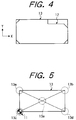
- a boundary rectangle 13 constructed by sides which are parallel with an X-axis and a Y-axis for a figure 12 of the outermost periphery of the electrode drawing.
- step S1 of the electrode drawing As shown in Fig. 5, it is judged that the origin symbol 11 at the origin position which was read in the reading step (step S1) of the electrode drawing is located near which one of four vertexes 13a to 13d of the boundary rectangle 13 and a crossing point 13e of diagonal lines, thereby setting the attributes of the upper left 13a, upper right 13b, lower left 13c, lower right 13d, and center 13e.
- step S3 After finishing the step (step S3), the CPU 1 automatically sets a processing range (step S4).
- step S4 of automatically setting the processing range will now be described in detail hereinbelow.
- the processing range will now be considered by dividing into a processing range R w in the width direction of the reference surface 10 and a processing range R h in the height direction of the reference surface 10.
- step S3 With respect to the processing range R w in the width direction of the reference surface 10, as shown in Fig. 6, lengths of the sides of the boundary rectangle 13, which was considered in the automatic recognizing step (step S3), at the position of the reference surface 10 are set to the processing range R w in the width direction of the first and second reference surfaces 10a and 10b, respectively.
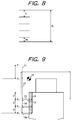
- the processing range R h in the height direction of the reference surface 10 will be obtained as follows. First, the reference surface 10 and a crossing line 14 of surfaces (A) and (B) adjacent to the reference surface 10 are obtained as shown in Fig. 7. Now, assuming that the maximum height of the crossing line 14 is set to H max and the minimum height of the crossing line 14 is set to H min and a depth of the reference surface read in the processing information reading step (step S2) is set to (D), the processing range R h in the height direction can be obtained by the following equation.
- the reference surface depth D denotes the minimum depth necessary for the reference surface 10.
- R h H max - H min + D
- step S4 When the step (step S4) is finished, the CPU 1 automatically calculates the number (N) of times of cutting and a cutting height H c (step S5).
- step S5 of automatically calculating the number (N) of times of cutting and the cutting height H c will be described in detail hereinbelow.
- the cutting amount (S) of the tool is referred to in the processing information reading step (step S2).
- the cutting height H c can be obtained by the following equation.
- H c H max - H min + N ⁇ S
- step S5 After finishing the step (step S5), the CPU 1 automatically decides a trace of the tool to be moved (step S6).
- Fig. 9 is a diagram showing a state of automatically deciding a trace of the tool to be moved in the height direction.
- Fig. 10 is a diagram showing a state of automatically deciding a trace of the tool to be moved in the width direction when the whole reference surface 10 is processed.
- Fig. 11 is a diagram showing a state of automatically deciding a trace of the tool to be moved in the width direction when both ends of the reference surface 10 are processed.
- step S6 of automatically deciding the trace of the tool to be moved as shown in Fig. 9, the trace of the tool to be moved in a manner such that the tool is dropped from a tool drop point P 1 to an origin position P 0 (C1) and to a first cutting height P 2 (C2) is determined.
- the tool is dropped only from a position higher than the origin position P 0 by an amount corresponding to the movement height to the first cutting height P 2 .
- the trace of the tool to be moved is determined in a manner such that the tool approaches the first reference surface 10a (C3) and cuts the reference surface 10a (C4) and, after that, the tool is escaped from the reference surface 10a (C5) and is moved to a next cutting height P 3 (refer to Figs. 9 and 10) (C6).
- the above operation is repeated until the trace of the tool to be moved with respect to a final cutting height P 4 is determined.
- the tool In the approach (C3) to the reference surface 10a, the tool is moved in the direction of approaching the reference surface 10a by a distance corresponding to (reference surface margin + approach amount + tool diameter/2).
- the tool In the cutting (C4) of the reference surface 10a, the tool is moved in the cutting direction of the tool by a distance corresponding to (processing range R w in the width direction + approach amount ⁇ 2) when the whole reference surface 10a is processed and the tool is moved by a distance corresponding to ⁇ (processing range R w in the width direction - both-ends reference surface width)/2 + approach amount ⁇ when both ends of the reference surface 10a are processed.
- the cutting direction of the tool denotes a direction when the process is executed so as to have a cutting object on the right-hand side.
- the tool In the escape (C5) from the reference surface 10a, the tool is moved by a distance corresponding to (reference surface margin + approach amount + tool diameter/2) in the direction of escaping from the reference surface 10a.
- step S6 When the step (step S6) is finished, whether both ends or the whole surface of the reference surface 10 is processed is judged. When it is judged that both ends are processed, the processing routine is returned to step S6 and a trace of the tool to be moved between the reference surfaces (C7) is formed as shown in Fig. 11.
- the tool In the movement of the tool between the reference surfaces (C7), the tool is moved in the cutting direction of the tool by a distance corresponding to the width of the reference surface. In the movement of the tool in the height direction, the tool is moved to a position higher than the origin position P 0 by a distance corresponding to the movement height.
- step S8 When it is judged that the whole surface is processed, whether two reference surfaces have been processed or not is judged (step S8). If it is judged to be "unprocessed", the processing routine is returned to step S6 and as shown in Fig. 10, in order to determine a trace of the tool to be moved for the other reference surface 10b, a trace (C8) of the tool to be moved from the first reference surface 10a to the second reference surface 10b is determined. After that, the automatic deciding step (step S6) of the trace of the tool to be moved is repeated with respect to the second reference surface 10b.
- the tool In the movement (C8) from the first reference surface 10a to the second reference surface 10b, the tool is moved in the approaching direction to the first reference surface 10a by a distance corresponding to (reference surface margin + tool diameter/2 + approach amount ⁇ 2 + processing range R w in the width direction of the second reference surface 10b) and the tool is moved in the direction opposite to the cutting direction of the tool of the first reference surface 10a by a distance corresponding to (reference surface margin + tool diameter/2 + approach amount ⁇ 2 + processing range R w in the width direction of the first reference surface 10a).
- step S8 When it is judged that the processes about two reference surfaces 10 of the first and second reference surfaces 10a and 10b have been finished in step S8, the processing routine is finished.
- the data of the trace of the tool to be moved which was formed as mentioned above is stored into the memory device 4 by the CPU 1.
- the complete automation in the decision of the trace of the tool to be moved in case of processing the reference surface of the electrode can be realized, the time and exertions can be reduced, and a variation in quality of the traces of the tool to be moved due to a difference of the capabilities of the human beings can be eliminated.
- the operation to decide the trace of the tool to be moved which is used for processing the reference surface of a solid such as an electrode can be automated in the numerical controlled discharge machine tool.
Landscapes
- Engineering & Computer Science (AREA)
- Manufacturing & Machinery (AREA)
- Human Computer Interaction (AREA)
- Physics & Mathematics (AREA)
- General Physics & Mathematics (AREA)
- Automation & Control Theory (AREA)
- Numerical Control (AREA)
- Electrical Discharge Machining, Electrochemical Machining, And Combined Machining (AREA)
Applications Claiming Priority (3)
| Application Number | Priority Date | Filing Date | Title |
|---|---|---|---|
| JP11018995A JP3347522B2 (ja) | 1995-04-11 | 1995-04-11 | 工具経路作成装置及び工具経路作成方法 |
| JP110189/95 | 1995-04-11 | ||
| US08/629,755 US5768136A (en) | 1995-04-11 | 1996-04-09 | Method and apparatus for deciding trace of tool to be moved |
Publications (2)
| Publication Number | Publication Date |
|---|---|
| EP0737931A2 true EP0737931A2 (fr) | 1996-10-16 |
| EP0737931A3 EP0737931A3 (fr) | 1997-09-17 |
Family
ID=26449864
Family Applications (1)
| Application Number | Title | Priority Date | Filing Date |
|---|---|---|---|
| EP96302523A Withdrawn EP0737931A3 (fr) | 1995-04-11 | 1996-04-10 | Procédé et appareil pour décider de la trajectoire d'un outil mouvant |
Country Status (3)
| Country | Link |
|---|---|
| US (1) | US5768136A (fr) |
| EP (1) | EP0737931A3 (fr) |
| JP (1) | JP3347522B2 (fr) |
Cited By (3)
| Publication number | Priority date | Publication date | Assignee | Title |
|---|---|---|---|---|
| EP0918268A3 (fr) * | 1997-11-24 | 2001-10-10 | Dieter Kragl | Procédé de fabrication de lithophanies |
| WO2007117508A3 (fr) * | 2006-03-30 | 2008-01-24 | Ugs Corp | méthode de sous-dimensionnement des électrodes pour l'usinage par etincelage à orbite polygonale |
| CN102566509A (zh) * | 2010-12-09 | 2012-07-11 | 中国科学院沈阳计算技术研究所有限公司 | 基于包络理论的数控加工仿真中通用刀具扫描体生成方法 |
Families Citing this family (27)
| Publication number | Priority date | Publication date | Assignee | Title |
|---|---|---|---|---|
| US6735489B1 (en) | 2000-01-14 | 2004-05-11 | Pravin Khurana | Horizontally structured manufacturing process modeling |
| US20020133266A1 (en) * | 2001-03-14 | 2002-09-19 | Landers Diane M. | Horizontally structured manufacturing process modeling for alternate operations, large parts and charted parts |
| US20020133267A1 (en) * | 2001-03-14 | 2002-09-19 | Landers Diane M. | Enhancement to horizontally structured manufacturing process modeling |
| US7110849B2 (en) * | 2001-03-14 | 2006-09-19 | Delphi Technologies, Inc. | Horizontally-structured CAD/CAM modeling for virtual fixture and tooling processes |
| US20020133265A1 (en) * | 2001-03-14 | 2002-09-19 | Landers Diane M. | Horizontally structured manufacturing process modeling for concurrent product and process design |
| US6839606B2 (en) * | 2001-03-14 | 2005-01-04 | Delphi Technologies, Inc. | Horizontally structured manufacturing process modeling for fixtures and tooling |
| US7308386B2 (en) * | 2001-03-14 | 2007-12-11 | Delphi Technologies, Inc. | Enhancement to horizontally-structured CAD/CAM modeling |
| US7099804B2 (en) | 2001-03-14 | 2006-08-29 | Delphi Technologies, Inc. | Automated horizontally structured manufacturing process design modeling |
| US6775581B2 (en) * | 2001-03-14 | 2004-08-10 | Delphi Technologies, Inc. | Horizontally-structured CAD/CAM modeling for virtual concurrent product and process design |
| US7280948B2 (en) * | 2002-01-31 | 2007-10-09 | Delphi Technologies, Inc. | System and method for integrating geometric models |
| US20030204286A1 (en) * | 2002-04-26 | 2003-10-30 | Thomas Steven M. | Method for modeling complex, three dimensional tool paths through a workpiece |
| US7024272B2 (en) * | 2002-04-26 | 2006-04-04 | Delphi Technologies, Inc. | Virtual design, inspect and grind optimization process |
| US7421363B2 (en) * | 2002-04-26 | 2008-09-02 | Delphi Technologies, Inc. | Method for virtual inspection of virtually machined parts |
| US20030234871A1 (en) * | 2002-06-25 | 2003-12-25 | Squilla John R. | Apparatus and method of modifying a portrait image |
| US7245984B2 (en) * | 2003-01-31 | 2007-07-17 | Delphi Technologies, Inc. | Horizontally structured manufacturing process modeling: exterior linked representational embodiment |
| US7079908B2 (en) * | 2003-01-31 | 2006-07-18 | Delphi Technologies,Inc. | Horizontally-structured modeling for analysis |
| US20040153296A1 (en) * | 2003-01-31 | 2004-08-05 | Landers Diane M. | Horizontally structured CAD/CAM coordinate system |
| US6754556B1 (en) | 2003-01-31 | 2004-06-22 | Diane M. Landers | Horizontally structured manufacturing process modeling: enhancement to multiple master process models and across file feature operability |
| US6985793B2 (en) * | 2003-01-31 | 2006-01-10 | Delphi Technologies, Inc. | Horizontally structured CAD/CAM coordinate system for manufacturing design |
| US6950719B2 (en) * | 2003-01-31 | 2005-09-27 | Delphi Technologies, Inc. | Horizontally structured manufacturing process modeling: across file feature operability |
| US7472044B2 (en) * | 2004-03-22 | 2008-12-30 | Delphi Technologies, Inc. | Horizontally structured CAD/CAM modeling-vertical to horizontal conversion |
| US7526359B2 (en) * | 2004-10-01 | 2009-04-28 | Delphi Technologies, Inc. | Enhanced digital process design methodology for process centric CAD systems |
| US9690282B2 (en) | 2011-02-28 | 2017-06-27 | Solidcam Ltd. | Computerized tool path generation |
| US8489224B2 (en) * | 2011-02-28 | 2013-07-16 | Solidcam Ltd. | Computerized tool path generation |
| US9644942B2 (en) * | 2012-11-29 | 2017-05-09 | Mitsubishi Hitachi Power Systems, Ltd. | Method and apparatus for laser projection, and machining method |
| KR101518005B1 (ko) * | 2014-06-30 | 2015-05-06 | 김윤기 | 오차 정보를 이용한 방전프로그램 생성장치, 그 생성방법 및 이를 이용한 방전시스템 |
| EP3602355A1 (fr) | 2017-03-20 | 2020-02-05 | Solidcam Ltd. | Système et procédé informatisés de génération d'un programme à commande numérique de fraisage sans broutement pour l'usinage d'une pièce à usiner |
Family Cites Families (12)
| Publication number | Priority date | Publication date | Assignee | Title |
|---|---|---|---|---|
| GB1497562A (en) * | 1976-03-12 | 1978-01-12 | Tack A | Machine tool control |
| DE3608438A1 (de) * | 1985-03-13 | 1986-09-18 | Toshiba Kikai K.K., Tokio/Tokyo | Verfahren zum berechnen von freien gekruemmten flaechen mittels computergestuetztem design cad und computergestuetzter herstellung cam und numerischer steuerung nc |
| JPH0766290B2 (ja) * | 1986-06-26 | 1995-07-19 | 東芝機械株式会社 | 工具経路生成方法 |
| US4907164A (en) * | 1988-09-26 | 1990-03-06 | General Electric Company | Automatically optimized NC tool path generation for machining |
| JPH0760336B2 (ja) * | 1988-12-28 | 1995-06-28 | オ−クマ株式会社 | 数値制御装置 |
| JP2691613B2 (ja) * | 1989-05-08 | 1997-12-17 | 菱電工機エンジニアリング株式会社 | Cad/cam装置 |
| US5043906A (en) * | 1989-11-24 | 1991-08-27 | Ford Motor Company | Absolute gouge avoidance for computer-aided control of cutter paths |
| DE69220263T2 (de) * | 1991-03-15 | 1997-11-27 | Spatial Technology Inc | Methode und Apparat für maschinelle Werkstückbearbeitung mittels eines solidmodel-Algorithmus |
| US5189626A (en) * | 1991-03-27 | 1993-02-23 | Caterpillar Inc. | Automatic generation of a set of contiguous surface patches on a computer modeled solid |
| GB9205046D0 (en) * | 1992-03-09 | 1992-04-22 | Queen Mary & Westfield College | Automated component production |
| JP2857540B2 (ja) * | 1992-06-22 | 1999-02-17 | ファナック株式会社 | カッタパスの自動再作成を行うcad/cam方法及び装置 |
| JP2905025B2 (ja) * | 1993-03-12 | 1999-06-14 | 三菱電機株式会社 | 数値制御情報作成装置およびその方法 |
-
1995
- 1995-04-11 JP JP11018995A patent/JP3347522B2/ja not_active Expired - Fee Related
-
1996
- 1996-04-09 US US08/629,755 patent/US5768136A/en not_active Expired - Lifetime
- 1996-04-10 EP EP96302523A patent/EP0737931A3/fr not_active Withdrawn
Cited By (5)
| Publication number | Priority date | Publication date | Assignee | Title |
|---|---|---|---|---|
| EP0918268A3 (fr) * | 1997-11-24 | 2001-10-10 | Dieter Kragl | Procédé de fabrication de lithophanies |
| WO2007117508A3 (fr) * | 2006-03-30 | 2008-01-24 | Ugs Corp | méthode de sous-dimensionnement des électrodes pour l'usinage par etincelage à orbite polygonale |
| US7428444B2 (en) | 2006-03-30 | 2008-09-23 | Siemens Product Lifecycle Management Software Inc. | Method for under-sizing electrodes for polygonal orbit electric discharge machining |
| EP2063335A1 (fr) * | 2006-03-30 | 2009-05-27 | Siemens Product Lifecycle Management Software Inc. | Procédé de sous-dimensionnement d'électrodes pour usinage par électroérosion à orbite électrique |
| CN102566509A (zh) * | 2010-12-09 | 2012-07-11 | 中国科学院沈阳计算技术研究所有限公司 | 基于包络理论的数控加工仿真中通用刀具扫描体生成方法 |
Also Published As
| Publication number | Publication date |
|---|---|
| JP3347522B2 (ja) | 2002-11-20 |
| EP0737931A3 (fr) | 1997-09-17 |
| JPH08281517A (ja) | 1996-10-29 |
| US5768136A (en) | 1998-06-16 |
Similar Documents
| Publication | Publication Date | Title |
|---|---|---|
| EP0737931A2 (fr) | Procédé et appareil pour décider de la trajectoire d'un outil mouvant | |
| US4757461A (en) | Process for graphically representing a structure | |
| EP0044192B2 (fr) | Procédé pour la préparation d'information pour une commande numérique | |
| EP0429276B1 (fr) | Système pour éviter le creusage pour commande assistée par ordinateur pour coupe de trajectoire | |
| CN115170580A (zh) | 板材加工控制方法、装置、计算机设备及存储介质 | |
| US4891763A (en) | NC program editing and programming device | |
| CN113182701A (zh) | 激光加工方法、装置、设备及存储介质 | |
| CN112037224B (zh) | 一种根据标注线生成轴线的方法、电子设备以及存储介质 | |
| EP0276312B1 (fr) | Procede pour calculer un vecteur normal | |
| CN117934942A (zh) | 焊缝识别模型及训练方法和焊缝跟踪方法 | |
| EP0237578A1 (fr) | Procede de formation d'une surface courbe composite | |
| JPH07262243A (ja) | 形状データチェック方法 | |
| JP2001092865A (ja) | Cad図面作成方法及び装置並びに寸法編集方法及び装置並びに記憶媒体 | |
| JP2002063219A (ja) | 設計装置、薄肉部検出表示方法、及び記憶媒体 | |
| JPH077292B2 (ja) | 2次元工具軌跡生成方法 | |
| US5151864A (en) | Method of generating cutting passes of complex curved surface | |
| JPH07129221A (ja) | 3次元工具経路のシミュレーション方法 | |
| JP3405827B2 (ja) | 図形処理装置および交点決定処理方法 | |
| JPH11175585A (ja) | 設計方法及び装置 | |
| JPH08194841A (ja) | 有限要素領域分割方法 | |
| JP2000153428A (ja) | Ncデ―タ作成装置、及び方法 | |
| JPH04174006A (ja) | グラフィック描画方法 | |
| CN120038413A (zh) | 加工设备控制方法、装置、设备及存储介质 | |
| Attila | IGES-based CAD model post processing module of a Setup and Fixture Planning System for box-shaped parts | |
| JPH1021410A (ja) | 立体イメージ画像の直交面認識方法及びその装置 |
Legal Events
| Date | Code | Title | Description |
|---|---|---|---|
| PUAI | Public reference made under article 153(3) epc to a published international application that has entered the european phase |
Free format text: ORIGINAL CODE: 0009012 |
|
| AK | Designated contracting states |
Kind code of ref document: A2 Designated state(s): DE GB |
|
| PUAL | Search report despatched |
Free format text: ORIGINAL CODE: 0009013 |
|
| AK | Designated contracting states |
Kind code of ref document: A3 Designated state(s): DE GB |
|
| 17P | Request for examination filed |
Effective date: 19980128 |
|
| 17Q | First examination report despatched |
Effective date: 20000309 |
|
| GRAP | Despatch of communication of intention to grant a patent |
Free format text: ORIGINAL CODE: EPIDOSNIGR1 |
|
| RIC1 | Information provided on ipc code assigned before grant |
Ipc: 7G 05B 19/4099 B Ipc: 7G 06F 17/50 A |
|
| RTI1 | Title (correction) |
Free format text: METHOD AND APPARATUS FOR DECIDING THE TRACE OF A TOOL TO BE MOVED |
|
| RIC1 | Information provided on ipc code assigned before grant |
Ipc: 7G 05B 19/4099 B Ipc: 7G 06F 17/50 A |
|
| STAA | Information on the status of an ep patent application or granted ep patent |
Free format text: STATUS: THE APPLICATION IS DEEMED TO BE WITHDRAWN |
|
| 18D | Application deemed to be withdrawn |
Effective date: 20050825 |