EP0739074A2 - Verdrahtungsfehlerdetektor einer Stromversorgung - Google Patents
Verdrahtungsfehlerdetektor einer Stromversorgung Download PDFInfo
- Publication number
- EP0739074A2 EP0739074A2 EP96105591A EP96105591A EP0739074A2 EP 0739074 A2 EP0739074 A2 EP 0739074A2 EP 96105591 A EP96105591 A EP 96105591A EP 96105591 A EP96105591 A EP 96105591A EP 0739074 A2 EP0739074 A2 EP 0739074A2
- Authority
- EP
- European Patent Office
- Prior art keywords
- power source
- pulse
- miswiring
- phase
- phase difference
- Prior art date
- Legal status (The legal status is an assumption and is not a legal conclusion. Google has not performed a legal analysis and makes no representation as to the accuracy of the status listed.)
- Granted
Links
Images

Classifications
-
- H—ELECTRICITY
- H02—GENERATION; CONVERSION OR DISTRIBUTION OF ELECTRIC POWER
- H02H—EMERGENCY PROTECTIVE CIRCUIT ARRANGEMENTS
- H02H7/00—Emergency protective circuit arrangements specially adapted for specific types of electric machines or apparatus or for sectionalised protection of cable or line systems, and effecting automatic switching in the event of an undesired change from normal working conditions
- H02H7/08—Emergency protective circuit arrangements specially adapted for specific types of electric machines or apparatus or for sectionalised protection of cable or line systems, and effecting automatic switching in the event of an undesired change from normal working conditions for dynamo-electric motors
- H02H7/097—Emergency protective circuit arrangements specially adapted for specific types of electric machines or apparatus or for sectionalised protection of cable or line systems, and effecting automatic switching in the event of an undesired change from normal working conditions for dynamo-electric motors against wrong direction of rotation
-
- G—PHYSICS
- G01—MEASURING; TESTING
- G01R—MEASURING ELECTRIC VARIABLES; MEASURING MAGNETIC VARIABLES
- G01R29/00—Arrangements for measuring or indicating electric quantities not covered by groups G01R19/00 - G01R27/00
- G01R29/18—Indicating phase sequence; Indicating synchronism
Definitions
- the present invention relates to a power source miswiring detection apparatus for detecting a miswiring of a power source of three-phase three-wire system or three-phase four-wire system to prevent an electronic equipment connected to the three-phase power source from suffering damage, failure or the like.
- an electronic equipment using the power source may be damaged, broken down or the like.
- an induction motor is used as an electronic equipment, in such an erroneous wiring situation the motor may rotate in the opposite direction to a desired direction, and it may be finally broken down.
- the respective phase wires of a power source is subjected to color-discrimination. The color discrimination is performed by coloring the respective phase wires with different colors so that the wires are visually discriminated from one another by a worker.
- miswiring is still unavoidable by such a conventional color-discriminating manner as described above when the miswiring is made due to a human-initiated failure (human error).
- An object of the present invention is to provide a power source miswiring detection apparatus for accurately detecting a miswiring of a power source (i.e., wires of a power source are erroneously connected) to prevent an electronic equipment using the power source from suffering damage, failure or the like even when a human error is made or the like.
- a power source miswiring detection apparatus for accurately detecting a miswiring of a power source (i.e., wires of a power source are erroneously connected) to prevent an electronic equipment using the power source from suffering damage, failure or the like even when a human error is made or the like.
- a power source miswiring detection apparatus for detecting a miswiring of wires of a power source, includes pulse generating means for generating a first pulse having a pulse width corresponding to a first phase difference between a first pair of two phases of a three-phase alternating power source, and a second pulse having a pulse width corresponding to a second phase difference between a second pair of two phases of the three-phase alternating power source which is different from the first pair of two phases, and judging means for detecting a third phase difference between the first pulse and the second pulse to judge whether the third phase difference is in a predetermined range, and detecting the miswiring if the third phase difference is judged to be out of the predetermined range.
- the power source miswiring detection apparatus as described above may further include frequency detection means for detecting the frequency of the three-phase alternating power source, wherein the predetermined range is determined in accordance with the frequency detected by the frequency detection means.
- the power source miswiring detection apparatus as described above may further include power source interrupting means for interrupting power supply of the three-phase alternating power source if the judging means judges the miswiring.
- the power source miswiring detection apparatus as described above may further include alarm means for outputting an alarm if the judging means judges the miswiring.
- the pulse generating mens generates the first pulse having the pulse width indicating the phase difference between the input first pair of two phases of the three-phase alternating power source, and generates the second pulse having the pulse width indicating the phase difference between the second pair of two phases of the alternating power source which is different from the first pair.
- the judging means determines the phase difference between the first pulse and the second pulse to judge whether the phase difference is in the predetermined range, and it detects the miswiring on the basis of the above judgment. That is, when a symmetrical three-phase alternating power source is used, the phase difference is normally equal to 120°. If there is any miswiring, the phase difference between two phases is different from 120°. Accordingly, the miswiring can be detected by checking the phase difference.
- a predetermined range is set to the reference (threshold) value of the phase difference for the judgment of the miswiring, and it is checked whether the detected phase difference is in this range.
- the present invention may be further equipped with the frequency detection means for accurately detecting the miswiring in accordance with the frequency of power.
- the reference value of the phase difference for the judgment of the miswiring is varied in accordance with the used power frequency.
- the present invention may be further provided with the power source interrupting means.
- the power source interrupting means interrupts the power supply from the three-phase alternating power source to protect an electronic equipment connected to the three-phase power source.
- the present invention may be provided with the alarm means.
- the alarm means When the judging means judges the miswiring, the alarm means outputs an alarm to alarm the miswiring to a worker.
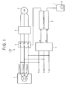
- Fig. 1 shows an embodiment of a power source miswiring detection apparatus according to an embodiment of the present invention.
- the power source miswiring detecting apparatus 100 includes a pulse generator 2 which is connected to a three-phase alternating power source 1 having three phases (R-phase, S-phase and T-phase), a microcomputer 3 connected to the pulse generator 2, an inverter 5, a power source switch 4 which is controlled by the microcomputer 3 to perform an on/off operation of power supply from the alternating power source 1 to the inverter 5, an induction motor 6 connected to the inverter 5, and a remote controller 7 which is connected to the microcomputer 3 and remotely controls the microcomputer 3.
- the remote controller 7 has a display unit 8 such as a liquid crystal display or the like.
- Fig. 2 is a circuit diagram showing the pulse generator 2 of the power source miswiring detection apparatus 100.
- the pulse generator 2 mainly includes a first diode Z1, a first photocoupler P1, a first low-pass filter which comprises a resistor R2 and a capacitor C1 and a first transistor Q1 which are used to generate a pulse A corresponding to a pulse between two phases (S-phase and T-phase) of the three-phase alternating power source 1, and further includes a second diode Z2, a second photocoupler P2, a second low-pass filter which comprises a resistor R3 and a capacitor C2, and a second transistor Q2 which are used to generate a pulse B corresponding to a pulse between two phases (T-phase and R-phase) of the three-phase alternating power source 1.
- the waveforms of the pulses A and B are shown in Fig. 3.
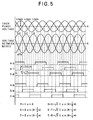
- the pulses A and B are generated as follows. As shown in Fig. 2, when the potential difference between the S-phase and the T-phase (i.e., the voltage waveform S-T of Fig. 5) is negative, current flows through the first diode Z1, but does not flow through a photodiode of the first photocoupler P1. On the other hand, when the potential difference is positive, current flows through the photodiode of the first photocoupler P1. At this time, a transistor of the first photocoupler P1 is responsive to light from the photodiode to be switched on, whereby the first transistor Q1 is switched on. Accordingly, the pulse A as shown in Fig. 5 is obtained at an output terminal of the pulse generator 2.
- the potential difference between the T-phase and the R-phase i.e., the voltage waveform T-R of Fig. 5
- the potential difference is negative
- current flows through the second diode Z2
- no current flows through a photodiode of the second photocoupler P2.
- the potential difference is positive
- current flows through the photodiode of the second photocoupler P2.
- a transistor of the second photocoupler P2 is responsive to light from the photodiode to be switched on, whereby the second transistor Q2 is switched on. Accordingly, the pulse B as shown in Fig. 5 is obtained at an output terminal of the pulse generator 2.
- Fig. 5 shows alternating waveform of a three-phase four-wire system having a power source frequency of 50Hz.
- an N-phase represents a neutral phase.
- the N-phase is generally grounded, and thus it is treated as 0V in Fig. 5.
- the pulse A corresponds to a pulse between the S-phase and the T-phase
- the pulse B corresponds to a pulse between the B-phase and the R-phase (see Fig. 5).
- the pulse width of each of the pulses A and B is equal to 10ms (milliseconds) as shown in Fig. 5.
- the pulse width of each of the pulses A and B is equal to 8.3ms (not shown).
- phase difference time lag
- TA-B time lag between the pulses A and B as shown in Fig. 3.
- the following table shows theoretical numeral values of the phase difference TA-B for all wiring combinations (24 wiring combinations or patterns) of the four phases (R,S,T,N) shown in Fig. 5. NO.
- each of the wiring combination Nos.1, 9 and 13 corresponds to a normal wiring
- the other wiring combinations correspond to the miswiring. Accordingly, as shown in the above table, when the power source frequency is set to 50Hz, the phase difference TA-B between the pulses A and B is equal to 6.7ms for the normal wiring. Further, when the power source frequency is set to 60Hz, the phase difference TA-B between the pulses A and B is equal to 5.6ms for the normal wiring. However, the phase different TA-B for the normal wiring may be deviated from the above values due to dispersion of the circuit construction. From actual measurements and experience, when the power source frequency is set to 50Hz, the phase difference TA-B of the pulses A and B for the normal wiring may be set in a range represented by the following inequality: 4ms ⁇ TA-B ⁇ 8ms
- phase difference TA-B of the pulses A and B for the normal wiring may be set in a range represented by the following inequality: 4ms ⁇ TA-B ⁇ 6.5ms
- the detection of the miswiring of the power source by the microcomputer of this embodiment is performed on the above assumption.
- the detailed procedure of the power source miswiring detection in the power source miswiring detection apparatus 100 of this embodiment will be described hereunder.
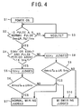
- Fig. 4 shows the power source miswiring detecting procedure of the microcomputer 3.
- the microcomputer 3 judges whether the pulse width WA of the pulse A and the pulse width WB of the pulse B satisfy the following inequalities, that is, the pulse widths WA and WB are set in the following ranges (step S2): 6ms ⁇ WA ⁇ 11ms 6ms ⁇ WB ⁇ 11ms.
- the pulse width of each of the pulses A and B is equal to 10ms for the power source of 50Hz, and the pulse width of each of the pulses A and B is equal to 8.3ms for the power source of 60Hz. That is, the value of the pulse width of each pulse is variable in a prescribed range.
- step S2 If the pulse width of the pulse A, B is judged to be out of the above range ("No" judgment) in step S2, the pulse is judged not to be a normal pulse, that is, the frequency of the power source is neither 50Hz nor 60Hz, and thus these pulses A and B are neglected (step S3).
- the pulse width of the pulse A, B is judged to be within the above range ("Yes” judgment)
- the pulse is judged to be a normal pulse and thus the process goes to step S4 to judge whether the period of the pulse is 18.5ms or more.
- the value of "18.5ms" is set for the following reason.
- the period of the pulse A, B is theoretically equal to 20ms for the power source of 50Hz, however, this value is variable in a prescribed range.
- the value of "18.5ms" is introduced in consideration of the prescribed range.
- step S4 If the period of the pulse is judged to be 18.5ms or more in step S4 ("Yes" judgement), the process goes to step S5 to judge that "the power source frequency is equal to 50Hz" because the power source frequency is set to 50Hz.
- step S6 the process goes to step S6 to judge whether the phase difference TA-B of the pulses A and B satisfies the following inequality: 4ms ⁇ TA-B ⁇ 8ms. If in step S6 the phase difference TA-B of the pulse A,B is judged to satisfy the following inequality:4ms ⁇ TA-B ⁇ 8ms ("Yes" judgment), the wiring concerned is judged to be the normal wiring, and thus the process goes to step S7 to judge that "power source wiring is normal".
- step S6 if the phase difference TA-B of the pulses A and B is judged to be out of the range of 4ms ⁇ TA-B ⁇ 8ms in step S6 ("No" judgment", the wiring concerned is judged to be a miswiring, and thus the process goes to step S10 to judge that "power source wiring is a miswiring".
- step S4 determines whether the period of the pulse is less than 18.5ms in step S4 ("No" judgment). If the period of the pulse is less than 18.5ms in step S4 ("No" judgment), the process goes to step S8 to judge that "the power source frequency is 60Hz" because the power source frequency is set to 60Hz.
- step S9 to judge whether the phase difference TA-B between the pulses A and B is out of the following range: 4ms ⁇ TA-B ⁇ 6.5ms. If the phase difference TA-B is within the range ("Yes" judgment), the wiring concerned is judged to be the normal wiring, and thus the process goes to step S7 to judge that "the power source wiring is normal". However, if in step S9 the phase difference TA-B of the pulses A and B is judged to be out of the following range:4ms ⁇ TA-B ⁇ 6.5ms ("No" judgment), the wiring is judged to be a miswiring, and thus the process goes to step S10 to judge that "the power source wiring is a miswiring".
- the microcomputer 3 If “the power source wiring is a miswiring" is judged in step S10, the microcomputer 3 outputs a switch OFF signal to the power source switch 4 to interrupt the power source 1 from the power source, whereby an electronic equipment using the power source 1 can be prevented from being damaged or broken down. Further, the microcomputer 3 outputs a display control signal to the remote controller 7 to display an alarm message indicating the miswiring on the display unit 8.
- the induction motor is used as an electronic equipment using the three-phase power source.
- the electronic equipment to which the present invention is applicable is not limited to the induction motor, and the present invention is applicable to any other electronic equipment using a three-phase alternating power.
- a power source wiring is judged to be a miswiring
- the power source is interrupted and an alarm indicating the miswiring is displayed.
- another indicating manner such as alarm sound (buzzer or the like) may be used.
- the three-phase four-wire system of wires having R-phase, S-phase, T-phase and N-phase is used.
- the present invention is applicable to a three-phase three-wire system.
- the pulse A corresponds to a first pulse
- the pulse B corresponds to a second pulse.
- the microcomputer 3, the power source switch 4 and the display unit 8 constitute the miswiring detecting means.
- the power source switch 4 corresponds to power source interrupting means
- the display unit 8 corresponds to miswiring alarming means.
- the miswiring of a power source can be checked by detecting the phase difference between two phases of the power source, whereby an electronic equipment using the power source can be prevented from being damaged or broken down.
- the miswiring can be accurately detected in accordance with the frequency of the power source.
- an electronic equipment which is connected to a three-phase power source can be protected by the power source interrupting means.
- the alarm means outputs an alarm to indicate the miswiring to a worker.
Landscapes
- Physics & Mathematics (AREA)
- General Physics & Mathematics (AREA)
- Testing Of Short-Circuits, Discontinuities, Leakage, Or Incorrect Line Connections (AREA)
- Emergency Protection Circuit Devices (AREA)
- Protection Of Static Devices (AREA)
Applications Claiming Priority (3)
| Application Number | Priority Date | Filing Date | Title |
|---|---|---|---|
| JP115175/95 | 1995-04-17 | ||
| JP7115175A JPH08289466A (ja) | 1995-04-17 | 1995-04-17 | 電源誤配線検知装置 |
| JP11517595 | 1995-04-17 |
Publications (3)
| Publication Number | Publication Date |
|---|---|
| EP0739074A2 true EP0739074A2 (de) | 1996-10-23 |
| EP0739074A3 EP0739074A3 (de) | 1998-03-18 |
| EP0739074B1 EP0739074B1 (de) | 2001-08-16 |
Family
ID=14656208
Family Applications (1)
| Application Number | Title | Priority Date | Filing Date |
|---|---|---|---|
| EP96105591A Expired - Lifetime EP0739074B1 (de) | 1995-04-17 | 1996-04-09 | Verdrahtungsfehlerdetektor einer Stromversorgung |
Country Status (7)
| Country | Link |
|---|---|
| US (1) | US5828309A (de) |
| EP (1) | EP0739074B1 (de) |
| JP (1) | JPH08289466A (de) |
| KR (1) | KR100211096B1 (de) |
| CN (1) | CN1078708C (de) |
| DE (1) | DE69614437T2 (de) |
| ES (1) | ES2162958T3 (de) |
Cited By (4)
| Publication number | Priority date | Publication date | Assignee | Title |
|---|---|---|---|---|
| FR2846487A1 (fr) * | 2002-10-29 | 2004-04-30 | Alain Durand | Dispositif de commande d'un moteur d'entrainement d'un element d'obturation d'une baie |
| EP1180840A3 (de) * | 2000-08-10 | 2005-06-08 | SANYO ELECTRIC Co., Ltd. | Schaltung zur Ermittlung einer negativen Phase einer Stromversorgung |
| CN102830326A (zh) * | 2011-06-16 | 2012-12-19 | 北京市电力公司 | 无线计量二次回路核线方法和系统 |
| CN105075084A (zh) * | 2013-03-29 | 2015-11-18 | 株式会社日立产机系统 | 电力转换装置 |
Families Citing this family (22)
| Publication number | Priority date | Publication date | Assignee | Title |
|---|---|---|---|---|
| SE509209C2 (sv) | 1997-11-28 | 1998-12-14 | Spectra Precision Ab | Anordning och förfarande för att bestämma läget för bearbetande del |
| JP2000228822A (ja) * | 1999-02-05 | 2000-08-15 | Tsubakimoto Chain Co | 過負荷保護装置及びこれを備えた減速機 |
| DE10205664B4 (de) * | 2002-02-12 | 2017-08-10 | Stiebel Eltron Gmbh & Co. Kg | Schaltung für einen Drehstrommotor |
| DE10239965A1 (de) * | 2002-08-30 | 2004-03-04 | Ramitek Gmbh | Vorrichtung zur optischen oder akustischen Anzeige für den mit dem Drehsinn der Phasen übereinstimmenden Anschluß eines Drehstromgerätes, insbesondere Drehstrommotors |
| US7400476B1 (en) * | 2003-12-10 | 2008-07-15 | Hull Jr Vernon M | Safety device for prevention of electrical shocks |
| JP2006038531A (ja) * | 2004-07-23 | 2006-02-09 | Toshiba Elevator Co Ltd | 三相交流電源の逆相検出装置 |
| CN100501429C (zh) * | 2005-12-13 | 2009-06-17 | 北京潞电电气设备厂 | 一种接线判别装置和方法 |
| WO2009082395A1 (en) * | 2007-12-21 | 2009-07-02 | Carrier Corporation | Method and system for low-power three-phase detection |
| JP5396034B2 (ja) * | 2008-03-31 | 2014-01-22 | 株式会社日立産機システム | 圧縮機の制御装置および電動モータの制御装置 |
| KR101614797B1 (ko) * | 2008-09-22 | 2016-04-22 | 삼성전자 주식회사 | 3상 역률 보상 보호 장치 및 그 제어방법 |
| JP5164030B2 (ja) | 2011-06-14 | 2013-03-13 | 株式会社安川電機 | 多軸モータ駆動システム及び多軸モータ駆動装置 |
| EP2904411B1 (de) * | 2012-10-08 | 2019-05-15 | Lodam Electronics A/S | Phasensequenznachweis |
| CN104020362B (zh) * | 2013-03-01 | 2017-04-12 | 珠海格力电器股份有限公司 | 三相负载调试控制电路 |
| US10018664B2 (en) | 2013-08-06 | 2018-07-10 | Mitsubishi Electric Corporation | Phase control device |
| CN104459355B (zh) * | 2013-09-24 | 2017-10-03 | 珠海格力电器股份有限公司 | 相序检测装置 |
| CN105785139B (zh) * | 2014-12-15 | 2021-04-16 | 丹佛斯(天津)有限公司 | 三相检测电路、三相检测方法和压缩机 |
| US10109996B2 (en) * | 2016-03-07 | 2018-10-23 | Whirlpool Corporation | Method and system for detecting miswiring of a power supply for a domestic appliance |
| KR101875628B1 (ko) * | 2016-07-15 | 2018-07-06 | 현대자동차 주식회사 | 오결선 검출 장치 및 방법 |
| EP3618213A1 (de) | 2018-07-23 | 2020-03-04 | Hoffman Enclosures, Inc. | Dreiphasige elektronische steuereinheit für gehäuseklimaanlagen |
| DE102018124124B3 (de) * | 2018-09-28 | 2019-10-10 | Sma Solar Technology Ag | Verfahren und Vorrichtung zur Identifikation einer Zuordnung von Phasenleitungen zu Anschlüssen eines schieflastfähigen elektrischen Gerätes |
| CN115597184B (zh) * | 2022-10-21 | 2024-07-23 | 珠海格力电器股份有限公司 | 防接错线保护方法、装置、空调器及存储介质 |
| WO2025162577A1 (en) * | 2024-01-31 | 2025-08-07 | Hitachi Energy Ltd | Automatic analysis of phase rotation and phase relationships |
Family Cites Families (6)
| Publication number | Priority date | Publication date | Assignee | Title |
|---|---|---|---|---|
| JPS52112355A (en) * | 1976-03-18 | 1977-09-20 | Shin Shirasuna Electric Corp | Method of detecting whether or not phase difference between two signals is constant |
| SU845114A1 (ru) * | 1979-03-22 | 1981-07-07 | Пензенский Завод Втуз При Заводе Вэм,Филиал Пензенского Политехническогоинститута | Способ установлени сдвига фаз междудВуМ гАРМОНичЕСКиМи СигНАлАМи |
| DE3211815C2 (de) * | 1982-03-31 | 1984-06-28 | Frako Kondensatoren- Und Apparatebau Gmbh, 7835 Teningen | Schaltungsanordnung zur Überwachung der Phasenfolge eines Drehstromnetzes |
| USRE33874E (en) * | 1986-05-22 | 1992-04-07 | Franklin Electric Co., Inc. | Electric motor load sensing system |
| JPH03244983A (ja) * | 1990-02-23 | 1991-10-31 | Toshiba Corp | 空気調和機 |
| US5184063A (en) * | 1992-02-13 | 1993-02-02 | Carrier Corporation | Three phase reversal detection system |
-
1995
- 1995-04-17 JP JP7115175A patent/JPH08289466A/ja active Pending
-
1996
- 1996-04-02 US US08/630,043 patent/US5828309A/en not_active Expired - Lifetime
- 1996-04-09 DE DE69614437T patent/DE69614437T2/de not_active Expired - Fee Related
- 1996-04-09 ES ES96105591T patent/ES2162958T3/es not_active Expired - Lifetime
- 1996-04-09 EP EP96105591A patent/EP0739074B1/de not_active Expired - Lifetime
- 1996-04-15 KR KR1019960011236A patent/KR100211096B1/ko not_active Expired - Fee Related
- 1996-04-15 CN CN96104620A patent/CN1078708C/zh not_active Expired - Fee Related
Cited By (7)
| Publication number | Priority date | Publication date | Assignee | Title |
|---|---|---|---|---|
| EP1180840A3 (de) * | 2000-08-10 | 2005-06-08 | SANYO ELECTRIC Co., Ltd. | Schaltung zur Ermittlung einer negativen Phase einer Stromversorgung |
| FR2846487A1 (fr) * | 2002-10-29 | 2004-04-30 | Alain Durand | Dispositif de commande d'un moteur d'entrainement d'un element d'obturation d'une baie |
| CN102830326A (zh) * | 2011-06-16 | 2012-12-19 | 北京市电力公司 | 无线计量二次回路核线方法和系统 |
| CN102830326B (zh) * | 2011-06-16 | 2015-04-08 | 国家电网公司 | 无线计量二次回路核线方法和系统 |
| CN105075084A (zh) * | 2013-03-29 | 2015-11-18 | 株式会社日立产机系统 | 电力转换装置 |
| EP2980978A4 (de) * | 2013-03-29 | 2017-02-15 | Hitachi Industrial Equipment Systems Co., Ltd. | Stromwandlervorrichtung |
| CN105075084B (zh) * | 2013-03-29 | 2017-10-13 | 株式会社日立产机系统 | 电力转换装置 |
Also Published As
| Publication number | Publication date |
|---|---|
| DE69614437D1 (de) | 2001-09-20 |
| KR100211096B1 (ko) | 1999-07-15 |
| CN1078708C (zh) | 2002-01-30 |
| CN1136170A (zh) | 1996-11-20 |
| EP0739074B1 (de) | 2001-08-16 |
| US5828309A (en) | 1998-10-27 |
| EP0739074A3 (de) | 1998-03-18 |
| KR960038404A (ko) | 1996-11-21 |
| DE69614437T2 (de) | 2002-05-16 |
| JPH08289466A (ja) | 1996-11-01 |
| ES2162958T3 (es) | 2002-01-16 |
Similar Documents
| Publication | Publication Date | Title |
|---|---|---|
| EP0739074A2 (de) | Verdrahtungsfehlerdetektor einer Stromversorgung | |
| EP1343016B1 (de) | Erkennungseinrichtung von Verdrahtungsfehlern für Klimaanlage | |
| KR100517122B1 (ko) | 돌입전류 방지용 저항기의 보호방법 | |
| US4979066A (en) | Loading controlling apparatus | |
| CA1207425A (en) | Residual differential device equipped with a surveillance system for the electronic power supply | |
| EP1265076B1 (de) | Sicherheitsvorrichtung für die Überwachung einer Gleichspannungsbusisolation | |
| GB2342455A (en) | Anti-static earth connection test system | |
| US5768077A (en) | Earthing wire disconnection detection apparatus and leakage detection apparatus having an earthing wire disconnection detection function conductor | |
| US5757275A (en) | Fault monitoring technique for programmable logic controllers | |
| US5644211A (en) | Malfunction prevention circuit for a battery charger | |
| US6946967B2 (en) | Protective device for an electric motor with sensor and evaluation unit | |
| EP0057498B1 (de) | Eine Schutzschaltung aufweisendes Gerät zur Überwachung der Erdisolierung | |
| KR100193949B1 (ko) | 반도체복합소자 및 그 소자를 사용한 인버터장치의 이상상태를 검출하는 방법 | |
| JPH09312928A (ja) | 空気調和機の欠相検知装置 | |
| RU2151458C1 (ru) | Устройство для защиты трехфазного электродвигателя от анормального режима | |
| JPH05316745A (ja) | 保護回路異常検出装置 | |
| KR200220599Y1 (ko) | 전기 자동차의 누설전류 검출장치 | |
| RU2122268C1 (ru) | Устройство для направленной защиты электрической сети от замыканий на землю | |
| JPH0568327A (ja) | 三相電源の欠相検出回路 | |
| KR930003181Y1 (ko) | 전열기구의 오동작 방지 보호 회로 | |
| KR200360753Y1 (ko) | 전기차제어장치의주변환기 | |
| SU1150690A1 (ru) | Устройство дл защиты от замыкани на землю электрической сети с изолированной нейтралью | |
| JPH0479208B2 (de) | ||
| KR890009155Y1 (ko) | 교류아크 용접기의 전기충격 방지기 | |
| SU1398012A1 (ru) | Устройство дл защиты электрической сети от токов короткого замыкани |
Legal Events
| Date | Code | Title | Description |
|---|---|---|---|
| PUAI | Public reference made under article 153(3) epc to a published international application that has entered the european phase |
Free format text: ORIGINAL CODE: 0009012 |
|
| AK | Designated contracting states |
Kind code of ref document: A2 Designated state(s): DE ES FR GB IT |
|
| PUAL | Search report despatched |
Free format text: ORIGINAL CODE: 0009013 |
|
| AK | Designated contracting states |
Kind code of ref document: A3 Designated state(s): DE ES FR GB IT |
|
| 17P | Request for examination filed |
Effective date: 19980602 |
|
| 17Q | First examination report despatched |
Effective date: 19981126 |
|
| GRAG | Despatch of communication of intention to grant |
Free format text: ORIGINAL CODE: EPIDOS AGRA |
|
| GRAH | Despatch of communication of intention to grant a patent |
Free format text: ORIGINAL CODE: EPIDOS IGRA |
|
| GRAH | Despatch of communication of intention to grant a patent |
Free format text: ORIGINAL CODE: EPIDOS IGRA |
|
| GRAA | (expected) grant |
Free format text: ORIGINAL CODE: 0009210 |
|
| AK | Designated contracting states |
Kind code of ref document: B1 Designated state(s): DE ES FR GB IT |
|
| REF | Corresponds to: |
Ref document number: 69614437 Country of ref document: DE Date of ref document: 20010920 |
|
| ET | Fr: translation filed | ||
| REG | Reference to a national code |
Ref country code: GB Ref legal event code: IF02 |
|
| REG | Reference to a national code |
Ref country code: ES Ref legal event code: FG2A Ref document number: 2162958 Country of ref document: ES Kind code of ref document: T3 |
|
| PLBE | No opposition filed within time limit |
Free format text: ORIGINAL CODE: 0009261 |
|
| STAA | Information on the status of an ep patent application or granted ep patent |
Free format text: STATUS: NO OPPOSITION FILED WITHIN TIME LIMIT |
|
| 26N | No opposition filed | ||
| PGFP | Annual fee paid to national office [announced via postgrant information from national office to epo] |
Ref country code: GB Payment date: 20050406 Year of fee payment: 10 |
|
| PGFP | Annual fee paid to national office [announced via postgrant information from national office to epo] |
Ref country code: DE Payment date: 20050407 Year of fee payment: 10 |
|
| PG25 | Lapsed in a contracting state [announced via postgrant information from national office to epo] |
Ref country code: GB Free format text: LAPSE BECAUSE OF NON-PAYMENT OF DUE FEES Effective date: 20060409 |
|
| PG25 | Lapsed in a contracting state [announced via postgrant information from national office to epo] |
Ref country code: DE Free format text: LAPSE BECAUSE OF NON-PAYMENT OF DUE FEES Effective date: 20061101 |
|
| GBPC | Gb: european patent ceased through non-payment of renewal fee |
Effective date: 20060409 |
|
| PGFP | Annual fee paid to national office [announced via postgrant information from national office to epo] |
Ref country code: FR Payment date: 20080312 Year of fee payment: 13 Ref country code: ES Payment date: 20080423 Year of fee payment: 13 |
|
| PGFP | Annual fee paid to national office [announced via postgrant information from national office to epo] |
Ref country code: IT Payment date: 20080424 Year of fee payment: 13 |
|
| REG | Reference to a national code |
Ref country code: FR Ref legal event code: ST Effective date: 20091231 |
|
| PG25 | Lapsed in a contracting state [announced via postgrant information from national office to epo] |
Ref country code: FR Free format text: LAPSE BECAUSE OF NON-PAYMENT OF DUE FEES Effective date: 20091222 |
|
| REG | Reference to a national code |
Ref country code: ES Ref legal event code: FD2A Effective date: 20090411 |
|
| PG25 | Lapsed in a contracting state [announced via postgrant information from national office to epo] |
Ref country code: ES Free format text: LAPSE BECAUSE OF NON-PAYMENT OF DUE FEES Effective date: 20090411 |
|
| PG25 | Lapsed in a contracting state [announced via postgrant information from national office to epo] |
Ref country code: IT Free format text: LAPSE BECAUSE OF NON-PAYMENT OF DUE FEES Effective date: 20090409 |