EP0740368A2 - Dispositif de rétention tubulaire - Google Patents
Dispositif de rétention tubulaire Download PDFInfo
- Publication number
- EP0740368A2 EP0740368A2 EP96302410A EP96302410A EP0740368A2 EP 0740368 A2 EP0740368 A2 EP 0740368A2 EP 96302410 A EP96302410 A EP 96302410A EP 96302410 A EP96302410 A EP 96302410A EP 0740368 A2 EP0740368 A2 EP 0740368A2
- Authority
- EP
- European Patent Office
- Prior art keywords
- retainer
- arm
- combination
- support structure
- wall
- Prior art date
- Legal status (The legal status is an assumption and is not a legal conclusion. Google has not performed a legal analysis and makes no representation as to the accuracy of the status listed.)
- Granted
Links
- 230000000295 complement effect Effects 0.000 claims 1
- 238000000465 moulding Methods 0.000 claims 1
- 229920003023 plastic Polymers 0.000 claims 1
- 239000004033 plastic Substances 0.000 claims 1
- 230000014759 maintenance of location Effects 0.000 abstract 1
- 230000037431 insertion Effects 0.000 description 5
- 238000003780 insertion Methods 0.000 description 5
- 238000010276 construction Methods 0.000 description 1
- 230000002093 peripheral effect Effects 0.000 description 1
- 238000005728 strengthening Methods 0.000 description 1
Images


Classifications
-
- H—ELECTRICITY
- H01—ELECTRIC ELEMENTS
- H01R—ELECTRICALLY-CONDUCTIVE CONNECTIONS; STRUCTURAL ASSOCIATIONS OF A PLURALITY OF MUTUALLY-INSULATED ELECTRICAL CONNECTING ELEMENTS; COUPLING DEVICES; CURRENT COLLECTORS
- H01R13/00—Details of coupling devices of the kinds covered by groups H01R12/70 or H01R24/00 - H01R33/00
- H01R13/46—Bases; Cases
- H01R13/52—Dustproof, splashproof, drip-proof, waterproof, or flameproof cases
- H01R13/5219—Sealing means between coupling parts, e.g. interfacial seal
Definitions
- the present invention relates to a tubular supporting structure, and particularly to such a structure for an electrical connector.
- a conventional retainer for a water-proof electrical connector is well-known as a tubular supporting structure.
- a cap-like retainer 1 is covered by the outer part of a housing 10 having terminal fitting insertion chambers 7, and doubly stops terminal fittings housed in the terminal fitting insertion chambers.
- the retainer 1 has an outer end wall 2 that faces out of the housing, and a surrounding side wall 3. Pairs of slits 4 are formed in a parallel manner on the side wall 3 as illustrated. The slits 4 extend from the inner side towards the outer side. Arms 5 are formed between the slits 4 and each has a free end. On the inner face of the arm 5 is formed a projection 6 that extends inwardly.
- a seal 13 is provided inboard of the retainer.
- the supporting force is weak since the arms 5 have free ends.
- the present invention has been developed after taking this problem into consideration, and aims at presenting a tubular supporting structure that can strengthen the supporting force and that can also make it robust.
- a tubular retainer and a support structure in combination, the retainer fitting with the support structure along a fitting axis, having a protruding wall and in the wall a flexible arm defined by spaced slits, the arm having a projection perpendicular to said axis and adapted for engagement with said support structure in use, wherein said flexible arm is secured at both ends thereof to said wall.
- the arm Since the arm is formed so as to be supported at both ends between the slits it is much stronger than the prior art construction. The arm is stiffer and the supporting force is thus increased. The arm is also less susceptible to damage since a free end is not provided.
- FIGURE 1 is an exploded isometric view of a water-proof connector using a tubular supporting structure according to an embodiment of the present invention.
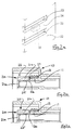
- FIGURE 2a is an enlarged isometric view of the essential part of the invention.
- FIGURE 2b is a partial section through a connector and showing one embodiment of the invention in the fully engaged state
- FIGURE 2c corresponds to Fig.2b and illustrates a partially engaged state
- FIGURE 3a is an exploded isometric view of a prior art water-proof connector
- FIGURE 3b corresponds to Fig.2a and shows a prior art arrangement
- FIGURE 3c corresponds to Fig.2c and shows a prior art arrangement.
- a water-proof connector housing 10 comprises a substantial tubular cavity member 11 having terminal fitting insertion chambers which allow terminal fittings to be housed therein, and a tubular hood member 12 that covers this cavity member 11.
- the cavity member 11 and the hood member 12 are connected towards the inner end so as to define a peripheral clearance around the cavity member, and an annular rubber seal 13 is attachable to the exterior side face of the inner extremity of the cavity member 11.
- a cap-like retainer 20 is arranged to be able to cover the extreme end of the cavity member 11.
- On an outer face 21 are formed a plurality of through holes 21a which correspond to each of the terminal fitting insertion chambers of the cavity member 11.
- a tubular side wall 22 is formed that extends from the edges of the outer face 21 towards the inner side. The outer end of the cavity member 11 is insertable within the side wall 22.
- the side wall 22 has slits 23 formed therein that extend towards the inner end.
- the slits 23 are formed in pairs on the side wall 22 and their extreme inner ends are closed.
- An arm 24 is formed between the slits 23 and which is fixed at both ends to the side face wall 22.
- a locking projection 25 is formed on the inner face of the arm 24 and which projects towards the cavity member 11 in use. Furthermore, on the side face of the cavity member 11 is formed an aperture 26 corresponding to the locking projection 25.
- the arm 24 Since the arm 24 is supported from both sides, only the central portion can bend inwards and outwards. As a result, compared to the conventional case where one extremity is free, a firm arm is achieved. Moreover, the rigidity of the arm 24 can be altered by changing the thickness and width of the arm 24.
- the retainer 20 has an outer wall 21 and is cap-like. However, it need not necessarily be cap-like as long as the arm 24, which can bend inwards and outwards, is formed on the side wall 22 for engagement with the cavity member 11.
- Figures 2b and 2c illustrate engagement of a retainer on a cavity member 11.
- Fig.2b shows the fully engaged condition, the linking portion at the free end of arm 24 being indicated by dotted line 27.
- Fig.2c illustrates how the mid portion of the arm 24 is urged outwardly as the retainer is engaged, and demonstrates that the engagement force is increased due to the increased stiffness.
- Terminal fittings are inserted into the terminal fitting insertion chambers of the cavity member 11, and the rubber seal 13 is fitted in the outer portion.
- the retainer 20 is inserted into the hood member 12, and the cavity member 11 makes contact with the locking projection 25 located on the inner side of the arm 24. Accordingly, the outer side of the cavity member 11 tries to push out the arm 24 via the locking projection 25.
- the arm 24 pushes the locking projection 25 towards the opening 26 with a strong force, and the supporting force is accordingly increased compared with the prior art. Moreover, since the arm 24 is supported from both ends, there is no possibility of damage as can happen in the case where one end is free, such damage occurring due to some object striking the free end, and possibly breaking off the arm. Strengthening is thereby effected.
- the invention has been described with the locking projection directed inwardly, it might also be directed outwardly for engagement of a retainer within a corresponding structure. What is important is that the locking arm is supported at both ends to increase the stiffness thereof, and project the arm from inadvertent damage.
Landscapes
- Connector Housings Or Holding Contact Members (AREA)
- Supports For Pipes And Cables (AREA)
Applications Claiming Priority (3)
| Application Number | Priority Date | Filing Date | Title |
|---|---|---|---|
| JP12721895 | 1995-04-26 | ||
| JP7127218A JPH08298151A (ja) | 1995-04-26 | 1995-04-26 | 筒体保持構造 |
| JP127218/95 | 1995-04-26 |
Publications (3)
| Publication Number | Publication Date |
|---|---|
| EP0740368A2 true EP0740368A2 (fr) | 1996-10-30 |
| EP0740368A3 EP0740368A3 (fr) | 1998-01-14 |
| EP0740368B1 EP0740368B1 (fr) | 1999-12-01 |
Family
ID=14954657
Family Applications (1)
| Application Number | Title | Priority Date | Filing Date |
|---|---|---|---|
| EP96302410A Expired - Lifetime EP0740368B1 (fr) | 1995-04-26 | 1996-04-04 | Dispositif de rétention tubulaire |
Country Status (5)
| Country | Link |
|---|---|
| US (1) | US5782658A (fr) |
| EP (1) | EP0740368B1 (fr) |
| JP (1) | JPH08298151A (fr) |
| CN (1) | CN1063257C (fr) |
| DE (1) | DE69605351T2 (fr) |
Cited By (1)
| Publication number | Priority date | Publication date | Assignee | Title |
|---|---|---|---|---|
| DE10113454B4 (de) * | 2000-03-21 | 2004-02-19 | Yazaki Corporation | Staubdichte Abdeckung für einen Steckverbinder und einstweilige Anordnung mit einer staubdichten Abdeckung und einem Steckverbinder |
Families Citing this family (18)
| Publication number | Priority date | Publication date | Assignee | Title |
|---|---|---|---|---|
| JP3286195B2 (ja) * | 1997-01-17 | 2002-05-27 | 矢崎総業株式会社 | ハウジングへのフロントホルダの係止構造 |
| US6142826A (en) * | 1998-03-13 | 2000-11-07 | The Whitaker Corporation | Sealed electrical connector with secondary locking member |
| FR2802347B1 (fr) * | 1999-12-08 | 2002-02-01 | Fci Automotive France | Connecteur electrique etanche, muni d'une grille avant de verrouillage des contacts |
| JP2002075519A (ja) * | 2000-09-04 | 2002-03-15 | Yazaki Corp | 防水コネクタ |
| JP4078963B2 (ja) * | 2002-11-27 | 2008-04-23 | 住友電装株式会社 | コネクタ |
| JP5569297B2 (ja) * | 2010-09-24 | 2014-08-13 | 住友電装株式会社 | 防水コネクタ |
| TWI429146B (zh) * | 2010-11-11 | 2014-03-01 | Wistron Corp | 電子裝置及其防水元件 |
| US8257111B1 (en) * | 2011-03-03 | 2012-09-04 | Delphi Technologies, Inc. | Sealed electrical splice assembly |
| WO2013013967A1 (fr) * | 2011-07-08 | 2013-01-31 | Fci Automotive Holding | Connecteur et ensemble de connexion |
| JP6106443B2 (ja) * | 2013-01-28 | 2017-03-29 | 矢崎総業株式会社 | シール部材及びシール構造 |
| JP2017084486A (ja) * | 2015-10-23 | 2017-05-18 | タイコエレクトロニクスジャパン合同会社 | コネクタ |
| EP3252876B1 (fr) * | 2016-06-01 | 2019-05-01 | Aptiv Technologies Limited | Prise électrique avec fonction de codage |
| US11309650B2 (en) * | 2017-08-01 | 2022-04-19 | Aptiv Technologies Limited | Sealed connector assembly |
| JP1646832S (fr) * | 2019-03-26 | 2019-12-02 | ||
| JP1645261S (fr) * | 2019-03-26 | 2019-11-11 | ||
| JP2021125362A (ja) * | 2020-02-05 | 2021-08-30 | 住友電装株式会社 | コネクタ |
| JP7256155B2 (ja) * | 2020-09-30 | 2023-04-11 | 矢崎総業株式会社 | コネクタ |
| JP2024053883A (ja) * | 2022-10-04 | 2024-04-16 | タイコエレクトロニクスジャパン合同会社 | シール部材およびコネクタ組立体 |
Family Cites Families (10)
| Publication number | Priority date | Publication date | Assignee | Title |
|---|---|---|---|---|
| US3474398A (en) * | 1967-09-20 | 1969-10-21 | Burndy Corp | Releasable locking connector |
| GB2071927B (en) * | 1980-03-14 | 1984-07-25 | Plessey Co Ltd | Retaining means for elongate members |
| JPH0249657Y2 (fr) * | 1984-07-31 | 1990-12-27 | ||
| JPH07105246B2 (ja) * | 1988-12-09 | 1995-11-13 | 矢崎総業株式会社 | コネクタの端子係止構造 |
| EP0420255B1 (fr) * | 1989-09-29 | 1996-05-01 | Yazaki Corporation | Dispositif de verrouillage pour connecteurs |
| US5163848A (en) * | 1990-09-27 | 1992-11-17 | Yazaki Corporation | Incomplete fitting prevention connector |
| US5192225A (en) * | 1990-11-08 | 1993-03-09 | Yazaki Corporation | Connector locking connection detection device |
| EP0484951B1 (fr) * | 1990-11-08 | 1996-09-04 | Yazaki Corporation | Dispositif de détection de verrouillage d'un connecteur |
| JPH0565996A (ja) * | 1991-09-06 | 1993-03-19 | Kubota Corp | 液化ガス充填装置 |
| JP2957084B2 (ja) * | 1994-04-08 | 1999-10-04 | 矢崎総業株式会社 | コネクタハウジング |
-
1995
- 1995-04-26 JP JP7127218A patent/JPH08298151A/ja active Pending
-
1996
- 1996-04-04 DE DE69605351T patent/DE69605351T2/de not_active Expired - Lifetime
- 1996-04-04 EP EP96302410A patent/EP0740368B1/fr not_active Expired - Lifetime
- 1996-04-26 CN CN96104915A patent/CN1063257C/zh not_active Expired - Lifetime
- 1996-04-26 US US08/638,208 patent/US5782658A/en not_active Expired - Lifetime
Cited By (1)
| Publication number | Priority date | Publication date | Assignee | Title |
|---|---|---|---|---|
| DE10113454B4 (de) * | 2000-03-21 | 2004-02-19 | Yazaki Corporation | Staubdichte Abdeckung für einen Steckverbinder und einstweilige Anordnung mit einer staubdichten Abdeckung und einem Steckverbinder |
Also Published As
| Publication number | Publication date |
|---|---|
| EP0740368A3 (fr) | 1998-01-14 |
| CN1140809A (zh) | 1997-01-22 |
| JPH08298151A (ja) | 1996-11-12 |
| DE69605351D1 (de) | 2000-01-05 |
| US5782658A (en) | 1998-07-21 |
| EP0740368B1 (fr) | 1999-12-01 |
| DE69605351T2 (de) | 2000-07-27 |
| CN1063257C (zh) | 2001-03-14 |
Similar Documents
| Publication | Publication Date | Title |
|---|---|---|
| US5782658A (en) | Tubular supporting structure | |
| US4776813A (en) | Sealed connector assembly | |
| EP0652607B1 (fr) | Connecteur étanché | |
| EP0677894B1 (fr) | Elément d'étanchéité et méthode de fabrication d'un connecteur étanche | |
| KR910004169B1 (ko) | 커 넥 터 | |
| US6679726B1 (en) | Panel mounted electrical connector | |
| US5158391A (en) | Sealing structure of waterproof connector | |
| US6059594A (en) | Sealed electrical connector | |
| JP2524946Y2 (ja) | 防水雌型コネクタハウジングの構造 | |
| JPH1027646A (ja) | コネクタ | |
| JPH07307182A (ja) | 防水ゴム栓および防水コネクタ | |
| JP6580548B2 (ja) | コネクタ | |
| JPH0722113A (ja) | 電気コネクタ及びそのハウジング | |
| US4486062A (en) | Waterproof connector | |
| US5944558A (en) | Connector with projected rib to guide the holder and the jig to control the connectivity of the terminal | |
| JPH04233176A (ja) | プラグコネクタ | |
| JP2849896B2 (ja) | 防水コネクタ | |
| JPH0727238U (ja) | 電気接続箱 | |
| JP4089468B2 (ja) | コネクタ | |
| JP3495996B2 (ja) | コネクタ | |
| EP1804340B1 (fr) | Structure de fixation pour couvercle arrière | |
| CN209977245U (zh) | 传感器及其密封件 | |
| CN119726212A (zh) | 端子壳体 | |
| JP3083057B2 (ja) | グロメットの位置決め構造及び逆付け検知機構 | |
| JP3239328B2 (ja) | 防水コネクタ |
Legal Events
| Date | Code | Title | Description |
|---|---|---|---|
| PUAI | Public reference made under article 153(3) epc to a published international application that has entered the european phase |
Free format text: ORIGINAL CODE: 0009012 |
|
| AK | Designated contracting states |
Kind code of ref document: A2 Designated state(s): DE FR GB |
|
| 17P | Request for examination filed |
Effective date: 19970210 |
|
| PUAL | Search report despatched |
Free format text: ORIGINAL CODE: 0009013 |
|
| AK | Designated contracting states |
Kind code of ref document: A3 Designated state(s): DE FR GB |
|
| 17Q | First examination report despatched |
Effective date: 19981002 |
|
| GRAG | Despatch of communication of intention to grant |
Free format text: ORIGINAL CODE: EPIDOS AGRA |
|
| 17Q | First examination report despatched |
Effective date: 19990324 |
|
| GRAG | Despatch of communication of intention to grant |
Free format text: ORIGINAL CODE: EPIDOS AGRA |
|
| GRAH | Despatch of communication of intention to grant a patent |
Free format text: ORIGINAL CODE: EPIDOS IGRA |
|
| GRAH | Despatch of communication of intention to grant a patent |
Free format text: ORIGINAL CODE: EPIDOS IGRA |
|
| GRAA | (expected) grant |
Free format text: ORIGINAL CODE: 0009210 |
|
| AK | Designated contracting states |
Kind code of ref document: B1 Designated state(s): DE FR GB |
|
| REF | Corresponds to: |
Ref document number: 69605351 Country of ref document: DE Date of ref document: 20000105 |
|
| ET | Fr: translation filed | ||
| PLBE | No opposition filed within time limit |
Free format text: ORIGINAL CODE: 0009261 |
|
| STAA | Information on the status of an ep patent application or granted ep patent |
Free format text: STATUS: NO OPPOSITION FILED WITHIN TIME LIMIT |
|
| 26N | No opposition filed | ||
| REG | Reference to a national code |
Ref country code: GB Ref legal event code: IF02 |
|
| PGFP | Annual fee paid to national office [announced via postgrant information from national office to epo] |
Ref country code: GB Payment date: 20020404 Year of fee payment: 7 |
|
| PG25 | Lapsed in a contracting state [announced via postgrant information from national office to epo] |
Ref country code: GB Free format text: LAPSE BECAUSE OF NON-PAYMENT OF DUE FEES Effective date: 20030404 |
|
| GBPC | Gb: european patent ceased through non-payment of renewal fee |
Effective date: 20030404 |
|
| REG | Reference to a national code |
Ref country code: FR Ref legal event code: PLFP Year of fee payment: 20 |
|
| PGFP | Annual fee paid to national office [announced via postgrant information from national office to epo] |
Ref country code: DE Payment date: 20150331 Year of fee payment: 20 |
|
| PGFP | Annual fee paid to national office [announced via postgrant information from national office to epo] |
Ref country code: FR Payment date: 20150408 Year of fee payment: 20 |
|
| REG | Reference to a national code |
Ref country code: DE Ref legal event code: R071 Ref document number: 69605351 Country of ref document: DE |