EP0743169A2 - Presse de fabrication de tablettes à table tournante - Google Patents
Presse de fabrication de tablettes à table tournante Download PDFInfo
- Publication number
- EP0743169A2 EP0743169A2 EP96303401A EP96303401A EP0743169A2 EP 0743169 A2 EP0743169 A2 EP 0743169A2 EP 96303401 A EP96303401 A EP 96303401A EP 96303401 A EP96303401 A EP 96303401A EP 0743169 A2 EP0743169 A2 EP 0743169A2
- Authority
- EP
- European Patent Office
- Prior art keywords
- die
- tabletting
- turret
- chamber
- press
- Prior art date
- Legal status (The legal status is an assumption and is not a legal conclusion. Google has not performed a legal analysis and makes no representation as to the accuracy of the status listed.)
- Granted
Links
Images




Classifications
-
- B—PERFORMING OPERATIONS; TRANSPORTING
- B30—PRESSES
- B30B—PRESSES IN GENERAL
- B30B15/00—Details of, or accessories for, presses; Auxiliary measures in connection with pressing
- B30B15/32—Discharging presses
-
- B—PERFORMING OPERATIONS; TRANSPORTING
- B30—PRESSES
- B30B—PRESSES IN GENERAL
- B30B11/00—Presses specially adapted for forming shaped articles from material in particulate or plastic state, e.g. briquetting presses, tabletting presses
- B30B11/02—Presses specially adapted for forming shaped articles from material in particulate or plastic state, e.g. briquetting presses, tabletting presses using a ram exerting pressure on the material in a moulding space
- B30B11/08—Presses specially adapted for forming shaped articles from material in particulate or plastic state, e.g. briquetting presses, tabletting presses using a ram exerting pressure on the material in a moulding space co-operating with moulds carried by a turntable
-
- B—PERFORMING OPERATIONS; TRANSPORTING
- B30—PRESSES
- B30B—PRESSES IN GENERAL
- B30B11/00—Presses specially adapted for forming shaped articles from material in particulate or plastic state, e.g. briquetting presses, tabletting presses
- B30B11/02—Presses specially adapted for forming shaped articles from material in particulate or plastic state, e.g. briquetting presses, tabletting presses using a ram exerting pressure on the material in a moulding space
- B30B11/08—Presses specially adapted for forming shaped articles from material in particulate or plastic state, e.g. briquetting presses, tabletting presses using a ram exerting pressure on the material in a moulding space co-operating with moulds carried by a turntable
- B30B11/085—Presses specially adapted for forming shaped articles from material in particulate or plastic state, e.g. briquetting presses, tabletting presses using a ram exerting pressure on the material in a moulding space co-operating with moulds carried by a turntable for multi-layer articles
-
- B—PERFORMING OPERATIONS; TRANSPORTING
- B30—PRESSES
- B30B—PRESSES IN GENERAL
- B30B15/00—Details of, or accessories for, presses; Auxiliary measures in connection with pressing
- B30B15/30—Feeding material to presses
- B30B15/302—Feeding material in particulate or plastic state to moulding presses
-
- B—PERFORMING OPERATIONS; TRANSPORTING
- B30—PRESSES
- B30B—PRESSES IN GENERAL
- B30B15/00—Details of, or accessories for, presses; Auxiliary measures in connection with pressing
- B30B15/30—Feeding material to presses
- B30B15/302—Feeding material in particulate or plastic state to moulding presses
- B30B15/304—Feeding material in particulate or plastic state to moulding presses by using feed frames or shoes with relative movement with regard to the mould or moulds
-
- B—PERFORMING OPERATIONS; TRANSPORTING
- B29—WORKING OF PLASTICS; WORKING OF SUBSTANCES IN A PLASTIC STATE IN GENERAL
- B29C—SHAPING OR JOINING OF PLASTICS; SHAPING OF MATERIAL IN A PLASTIC STATE, NOT OTHERWISE PROVIDED FOR; AFTER-TREATMENT OF THE SHAPED PRODUCTS, e.g. REPAIRING
- B29C43/00—Compression moulding, i.e. applying external pressure to flow the moulding material; Apparatus therefor
- B29C43/32—Component parts, details or accessories; Auxiliary operations
- B29C43/34—Feeding the material to the mould or the compression means
- B29C2043/3477—Feeding the material to the mould or the compression means centrally fed, e.g. feeding the material in the center of the mould turntables
Definitions
- the present invention relates to a rotary tabletting press for production of tablets from tabletting material.
- powdered or granulated material to be tabletted is fed onto the surface of a rotating die table within the confines of a feeder so as to fill dies in the die table as a die table rotates underneath the feeder.
- the surface of the die table rotates largely in an environment of fresh air, whilst product is introduced to that surface locally by means of the feeder.
- the quantity of material delivered to the die cavity is determined by the position of the lower punch in the die cavity and the effect of the trailing edge of the feeder scraping across the upper opening of the die cavity thereby leaving a metered dose within the die cavity.
- Opposed pairs of vertically reciprocal punches operate to enter the dies from opposite ends and are operated by stationary cams.
- Means is provided for adjusting the cams in order to adjust the amount of material which is compressed in each die to form each tablet and to control the thickness of the resulting tablet.
- the finished tablet is ejected upwardly through the upper opening of the die cavity by upward movement of the lower punch.
- the upper punches is elevated to permit this.
- the present invention provides a rotary tabletting press for the production of tablets from tabletting material, comprising a turret driven to rotate about its own axis with respect to a stationary housing and carrying rotatably with it:-
- the means to control dosing of the die cavities comprises a blade intercepting the pitch circle diameter of the die cavities. More especially, the blade is disposed adjacent the upper surface of the die plate and acts to remove tabletting material from the die plate over a prescribed arc immediately before entry of the upper punch into the die cavity. More particularly still, the above-described chamber is preferably enclosed within the turret, for example and by a peripheral wall. Conveniently, the wall extends upwardly and radially inwardly to incorporate the upper punch guides and to form a dust-proof enclosure penetrated only by a product feed duct. Feeding of tabletting material to the chamber conveniently takes place down a centrally positioned filling tube which opens into the chamber. Supplementary chevrons, deflectors or rotating paddles can be arranged above the die table if required.
- the infeed of material to the chamber may be offset from the central axis of the turret.
- the peripheral wall of the turret is rotatable with the turret.
- Another aspect of the present invention aims to provide a solution.
- a rotary tabletting press for the production of tablets from tabletting material, comprising a turret driven to rotate about its own axis with respect to a stationary housing and carrying rotatably with it:-
- the successive die cavities are filled with material as they pass under the local feeder.
- the position of the lower punch within the cavity determines the amount of material admitted to the die cavity.
- an overfilling takes place, in a conventional manner, with the lower punch being moved upwardly to discharge material into the feeder, before the trailing edge of the feeder acts as a scraper to leave the prescribed quantity of material in the die.
- the upper punch is then lowered into the die cavity to carry out the tabletting operation.
- the above-described chamber is preferably enclosed within the turret, for example by a peripheral wall. Conveniently, the wall extends upwardly and radially inwardly to incorporate the upper punch guides and to form a dust-proof enclosure penetrated only by a product feed duct.
- Feeding of tabletting material to the or each stationary tablet feeder conveniently takes place down a centrally positioned passage formed in the turret. Separate passageways are conveniently provided for each filler so that different materials (be they compositions or merely colours) can used.
- the charging of the die cavities follows standard practice, but with the advantage that the feeders are accommodated within an enclosed chamber of the turret.
- the tabletting material is fed to the local feeders from within the turret. It is preferred that the peripheral wall of the chamber is rotatable with the turret.
- the number of feeders provided will depend on the number of tablet material pressing operations (for a given die) which are to be carried out in the course of one revolution of the turret.
- the chamber may be defined at least in part by a stationary wall element disposed in close proximity to the rotatable turret.
- a stationary wall element disposed in close proximity to the rotatable turret.
- Advantageously means is provided to effect a seal between the adjacent stationary and rotary parts, at least to a sufficient extent to achieve containment of the tabletting material without unacceptable leakage.
- the wall may define the peripheral extent of the chamber and material may be fed to the chamber from within the turret.
- a stationary wall element makes possible the infeed of tabletting material from a position radially outwardly of the turret.
- the stationary wall element may be in the form of an annular element disposed around the turret and may incorporate one or more feed passages communicating with the chamber or may have a continuous circumferential opening into said chamber.
- the aforesaid blade may be carried from said stationary element.
- tabletting material moves freely across substantially the entire surface of die plate to rotate with it, with only a small area of the die table cleared of product to leaving the desired metered quantity in the successive die chambers passing the dosing blade.
- This is conveniently carried out by a stationary scraper blade depending from a stationary part of the housing which serves to deflect material from the pitch line over the short arc required between positioning of the lower punch at the prescribed depth in the die and entry of the upper punch.
- the scraper serves to scavenge material from the top of the overfilled die and deflect the rotating bed of product radially inwards until the metered dose is safely sealed by the tip of the upper punch.
- the means to control the quantity of tabletting material admitted to the die cavities may be the controlled movement of the upper and lower punches. For example, simultaneous spaced apart movement of the opposed upper and lower punches in the presence of tabletting material can be used to draw a measured quantity of material into the die.
- Tablet ejection is downwardly through the lower opening of the die cavity.
- an advantageous die clamping mechanism for the rotary tablet press employs at least one die clamping element, by which several dies can be located simultaneously.
- a tolerance compensation element is disposed between each die and at least one of the die clamping element and the die table to take up tolerances.
- a particulary convenient embodiment of the tolerance compensator is a resilient O-ring. The resilience is in the opposite direction to the main tablet ejection force.
- the die clamping element conveniently comprises an annular ring having a plurality of bores corresponding in number to the number of dies.
- at least one end of the die has a reduced diameter portion whereby all the dies can be located simultaneously and said reduced diameter end fits snugly into a respective said bore of the clamping element.
- each die has a shoulder which makes axial engagement with a shoulder of a corresponding bore in the die table. Contact is preferably direct in the direction of tablet ejection.
- a preferred die comprises a cylindrical element having reduced diameter portions to opposite ends whereby the die can be inserted either way around.
- the outer periphery of the die is relieved to receive an anti-rotation member which cooperates with it and the die table.
- any angular location device for the die as concealed from the upper face of the die table and preferably also from the lower surface of the die table. This is advantageous as it avoids the need for additional gaps or cavities in these surfaces which could entrap tabletting material or cause other snagging hazards.
- the angular location device could form part of the clamping element.
- Another aspect of the invention concerns controlling flow of tabletting material onto the die table and proposes a sensor monitoring the amount of material on the die table and controlling the opening of a feed gate in response to demand for tabletting material.
- the end of the feeding tube which opens onto the die table is movable in response to signals from the position sensor.
- a rotary tabletting press comprises a stationary housing 1 accommodating a drive shaft 2 journalled for rotation in the housing in a conventional manner (not shown) and having an axis of rotation R and having mounted thereon in driving connection therewith a lower part 3 of a rotatable turret.
- the lower part incorporates a plurality of circumferentially spaced bores 5 for respective lower punches of opposed pairs of upper and lower punches.
- the lower part includes an annular die plate 7 accommodating a plurality of circumferentially spaced die cavities 9 set on a common pitch circle diameter coaxial with the axis of a shaft 2 in a conventional manner.
- a conical deflection plate 11 extends from the axis of the turret radially outwardly and downwardly to the upper surface of the die plate 7.
- the turret further comprises an upper part 13 accommodating upper punch housings 15 with a plurality of circumferentially spaced bores 16 for the upper punches, and a peripheral wall element 17 which contacts the die plate 7.
- a tabletting material chamber 19 is defined radially inwardly of the wall 17 and between the upper and lower parts 3 and 13 of the turret.
- the upper turret part 13 is journalled for rotation on a stationary spindle 21 which incorporates a coaxial tablet material feed passage 23 feeding material to the chamber 19.
- a stationary scraper blade 25 extends from the stationary spindle 21 being connected thereto by a support arm 27.
- Respective pairs of upper and lower punches 31, 33 controlled by respective upper and lower cams are slidably guided in the respective bores 16, 5 of the upper and lower punch housings to be entrant into the die cavity 9 according to the prescribed working cycle.
- the punches are shown in Figure 3 by way of example. In a single-sided machine a pair of opposed compression rolls (not illustrated) act on the respective upper and lower punches at final compression, as is well known in the art.
- the scraper blade 25 extends radially inwardly from a position in close proximity with the circumferential wall 17 so as to clear tabletting material from the die plate over an area intercepted by the die cavities 9 and for a short arc ⁇ of the revolution of the turret sufficient to allow entry of the upper punch into the die cavity.
- the compression cycle largely follows conventional practice, for example using stationary cams and compression rolls, with tablet ejection occurring approximately 180° from entry of the upper punch into the die cavity. However, ejection is by downward movement of the upper punch to eject the completed tablet from the lower opening of the die cavity into a take-off chute 35.
- a take off blade 41 is positioned to wipe the lower surface of the die plate 7 (see Figure 4).
- a supplemental stationary blade 25' may be provided to distribute tabletting material over the die plate, and specifically outwardly toward the pitch circle diameter of the die cavities.
- the angle of the surface 11 will be chosen to aid outward movement of the tabletting material from the infeed passage.
- the invention may also be applied to a so-called double-sided machine in which there are two pairs of compression rolls, and appropriately profiled cam tracks, for example for producing two tablets per revolution of the turret or for producing double layer tablets.
- an additional scraper blade is provided to meter the quantity of tabletting material to be admitted to the die cavity before entry of the upper punch for a second time.
- Additional material guides may be provided within the chamber to guide the tabletting material outwardly into the path of the dies.
- a second take-off blade and chute is provided as necessary.
- the discrete tablet feeders would be required.
- the upper part is intended to be separable from the lower part, separation requiring upward axial movement of the upper part. Separation occurs where the upper turret part meets the die plate of the lower turret part.
- the elevating means and the clamping means is not described in further detail.
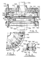
- FIG. 5 there is illustrated a vertical section showing part of a rotary tabletting press according to another embodiment and comprising a rotatable turret having upper and lower parts 100, 102.
- the lower part is driven rotatably from a main drive shaft 104 which is journalled in the housing of the tablet press, not further illustrated.
- the upper housing part is keyed to a die table 106 of the lower housing part by way of three locating pins, see for example 108.
- a jacking system (not illustrated) controls relative axial movement of the upper and lower housing parts.
- a clamping system holds the upper part to the lower part in use.
- the upper half is axially movable for separation and the lower half fixed.
- the upper half is mounted in a way which allows limited angular pivoting of the turret about a horizontal axis once it has been elevated.
- One upper punch is shown at 110 guided for reciprocal movement in a bore 112 of the upper housing part.
- the die table 106 has a plurality of stepped through bores 114 to accommodate a respective die 116 shown further in Figures 8, 9 and 10.
- the lower housing part 102 has a plurality of bores 118 each accommodating a respective lower punch 120. It will be understood that there is respective upper and lower punch 110, 120 for each die 116 and these are set on a common pitch circle diameter relative to the axis of rotation of the turret. Movement of the upper and lower punches is controlled by respective upper and lower stationary cams and by compression rolls (not illustrated) as is common in the art.
- FIG. 5 shows the upper and lower housing parts in their closed position ready for use.
- a material feed chamber 122 is formed within the turret partly by components of the lower housing part and partly by components of the upper housing part. Tabletting material is brought into the chamber down a feed tube 124 having an open end 126 which can be moved relative to a feed cone 128.
- a feeder mechanism for controlling distribution of tabletting material across the die table to the dies is carried from a stationary shaft 130 conveniently passing through the main drive shaft and attached to the machine structure, for example at the main gear box. Part of the feeder mechanism is shown schematically at 132.
- One embodiment is described further with reference to Figure 11.
- Each die 116 comprises a central outer diameter portion 134 and two reduced diameter end portions 136, 138 defining axially orientated shoulders 140, 142.
- Each die has a through bore forming the respective die cavities 90 of the die table.
- the outer periphery of central enlarged portion 134 has an arcuate cut-out 144 to receive a cylindrical key 146 for locating a die against rotation.
- the bore 114 in the die table has larger and smaller diameter portions 114a, 114b defining an axial shoulder 148 against which one of shoulders 140, 142 of the die engages according to the orientation of the die.
- annular die clamping ring 150 which has a plurality of bores 152 dimensioned to receive either one of the reduced diameter portions 136, 138 of the die 116 so that either end face 154, 156 of the die finishes flush with the upper surface 158 of the die clamping ring.
- An O-ring 160 fits between the upper facing axial shoulder of the die and the underside axial surface 162 of the die clamping ring.
- the die clamping ring can be secured to the die table by a plurality of bolts but more conveniently it is located by the axial positioning of the upper turret housing part onto the lower turret housing part which brings a cooperating part 170 into engagement with the outer rim 150 of the die clamping element.
- Component 170 conveniently comprises a seal retaining ring which makes cooperating engagement with the upper housing part 100 and also serves to retain respective upper punch seals 172.
- the peripheral wall of the material containment chamber is formed by the respective rim parts of the die clamping ring and the seal retaining ring 170.
- a centre cover plate 174 fits within the annular die clamping ring 150 and lies flush with the upper surface 158 thereof.
- the die clamping arrangement illustrated in Figures 5, 6 and 7 is employed where there is downward tablet ejection. In a case where there is upward table ejection, the clamping element would be positioned on the underside of the die table.
- the top of the die table is shown schematically at 200 and has a plurality of bores each receiving a respective die 216.
- the direction of rotation of the die table is represented by arrow A.
- a rotationally fixed feeding tube 224 opens onto the die table 200.
- the feeding tube opens onto a cone similar to that illustrated in Figure 5.
- a spiral deflector arm 226 which serves to move material radially outwards from the base of the cone 228 to the inside of a feeder wall 230.
- a main scraper 228 removes surplice material from the die faces and returns it to the inside of the feeder wall 230 which forms a continuation of the main scraper disposed radially inwardly of the dies.
- the main scraper is in close contact with the die table until the upper punch has entered the die thereby ensuring the correct metered dose. Thereafter the feeder wall may be slightly spaced from the die table as some leakage past the feeder wall is immaterial once the upper punch has entered the die.
- an arcuate deflector 232 which serves to move material radially outwards to the pitch line of the dies and is disposed in a position corresponding generally to that where filling would start in relation to the arcuate movement of the die table.
- the spiral deflector 226 terminates radially inwardly of the feeder wall and a pivoted sensing vane 234 is disposed between it and the feeder wall. Its angular position is responsive to the quantity of material disposed on the die plate.
- a micro switch or proportional sensor 236 monitors movement of the pivoted sensing vane and serves to adjust the quantity of material flowing onto the die table in response to demand.
- the feeding tube is moved axially with respect to the distribution cone so that the open end of the feeding tube moves between a closed position where it contacts the cone and an open position. Movement may be continuously variable or between open and closed positions.
- the spiral deflector 226 is positioned so as to form a continuation of the arcuate deflector 232 as shown in dotted outline.
- a rotary tabletting press comprises a stationary housing 301 accommodating a drive shaft 302 journalled for rotation in the housing in a conventional manner (not shown) and having an axis of rotation R and having mounted thereon in driving connection therewith a lower part 303 of a rotatable turret.
- the lower part incorporates a plurality of circumferentially spaced bores 305 for respective lower punches of opposed pairs of upper and lower punches.
- the lower part includes an annular die plate 7 accommodating a plurality of circumferentially spaced die cavities 9 set on a common pitch circle diameter coaxial with the axis of a shaft 302 in a conventional manner.
- the turret further comprises an upper part 313 accommodating upper punch housings 315 with a plurality of circumferentially spaced bores 316 for the upper punches, and a peripheral wall element 317 which contacts the die plate 307.
- a chamber 319 is defined radially inwardly of the wall 317 and between the upper and lower parts 303 and 313 of the turret.
- the upper turret part 313 is journalled for rotation on a stationary spindle 321 which incorporates two coaxial tablet material feed passage 323, 324 feeding material to respective local stationary tabletting material feeders 326, 328 disposed diametrically opposite one another in the illustration.
- Each feeder comprises a compartment open to the underside and placed to make sliding engagement with the upper surface of the die plate and extending over a prescribed distance. Tabletting material is fed to the respective feeders via a respective radial passage 327 from a respective infeed passage 323, 324.
- Respective pairs of upper and lower punches 331, 333 controlled by respective upper and lower cams (not illustrated) are slidably guided in the respective bores 316, 305 of the upper and lower punch housings to be entrant into the die cavity 309 according to the prescribed working cycle.
- the punches are shown in Figure 14 by way of example.
- the respective local feeders 326, 328 are positioned so that the die cavities intercept them so that tabletting material from the feeder enters successive die cavities 309 as they pass during rotation of the turret.
- the circumferential extent of the feeders is sufficient to allow entry of the tabletting material into the die.
- the upper punch enters the die cavity when it is clear of the feeder.
- the compression cycle largely follows conventional practice, for example using stationary cams and compression rolls.
- tablet ejection is by downward movement of the upper punch to eject the completed tablet from the lower opening of the die cavity into a take-off chute (not illustrated).
- a take-off blade may be provided to wipe the lower surface of the die plate 307.
Landscapes
- Engineering & Computer Science (AREA)
- Mechanical Engineering (AREA)
- Medical Preparation Storing Or Oral Administration Devices (AREA)
- Medicinal Preparation (AREA)
- Encapsulation Of And Coatings For Semiconductor Or Solid State Devices (AREA)
- Pharmaceuticals Containing Other Organic And Inorganic Compounds (AREA)
- Specific Conveyance Elements (AREA)
- General Preparation And Processing Of Foods (AREA)
- Saccharide Compounds (AREA)
- Processing And Handling Of Plastics And Other Materials For Molding In General (AREA)
Priority Applications (1)
| Application Number | Priority Date | Filing Date | Title |
|---|---|---|---|
| EP01117417A EP1164001B1 (fr) | 1995-05-18 | 1996-05-14 | Presse pour comprimés à table rotative |
Applications Claiming Priority (6)
| Application Number | Priority Date | Filing Date | Title |
|---|---|---|---|
| GBGB9510068.1A GB9510068D0 (en) | 1995-05-18 | 1995-05-18 | Rotary tabletting press |
| GB9510068 | 1995-05-18 | ||
| GBGB9512377.4A GB9512377D0 (en) | 1995-06-17 | 1995-06-17 | Rotary tabletting press |
| GB9512377 | 1995-06-17 | ||
| GBGB9609380.2A GB9609380D0 (en) | 1996-05-10 | 1996-05-10 | Rotary tabletting press |
| GB9609380 | 1996-05-10 |
Related Child Applications (1)
| Application Number | Title | Priority Date | Filing Date |
|---|---|---|---|
| EP01117417A Division EP1164001B1 (fr) | 1995-05-18 | 1996-05-14 | Presse pour comprimés à table rotative |
Publications (3)
| Publication Number | Publication Date |
|---|---|
| EP0743169A2 true EP0743169A2 (fr) | 1996-11-20 |
| EP0743169A3 EP0743169A3 (fr) | 1997-09-24 |
| EP0743169B1 EP0743169B1 (fr) | 2002-02-13 |
Family
ID=27267727
Family Applications (2)
| Application Number | Title | Priority Date | Filing Date |
|---|---|---|---|
| EP01117417A Expired - Lifetime EP1164001B1 (fr) | 1995-05-18 | 1996-05-14 | Presse pour comprimés à table rotative |
| EP96303401A Expired - Lifetime EP0743169B1 (fr) | 1995-05-18 | 1996-05-14 | Presse de fabrication de tablettes à table tournante |
Family Applications Before (1)
| Application Number | Title | Priority Date | Filing Date |
|---|---|---|---|
| EP01117417A Expired - Lifetime EP1164001B1 (fr) | 1995-05-18 | 1996-05-14 | Presse pour comprimés à table rotative |
Country Status (7)
| Country | Link |
|---|---|
| US (1) | US6068465A (fr) |
| EP (2) | EP1164001B1 (fr) |
| JP (1) | JPH09122996A (fr) |
| CN (2) | CN1524684A (fr) |
| AT (2) | ATE213199T1 (fr) |
| CA (1) | CA2176412C (fr) |
| DE (2) | DE69634348D1 (fr) |
Cited By (5)
| Publication number | Priority date | Publication date | Assignee | Title |
|---|---|---|---|---|
| EP0823324A1 (fr) * | 1996-08-09 | 1998-02-11 | Courtoy | Presse de fabrication de tablettes à table tournante |
| CN102173082A (zh) * | 2011-01-18 | 2011-09-07 | 西安交通大学 | 一种低能耗高出力的多样化生物质压型设备 |
| RU2487017C1 (ru) * | 2012-02-09 | 2013-07-10 | Открытое акционерное общество "Производственное объединение "Завод имени Серго" | Роторная таблеточная машина |
| RU2487800C1 (ru) * | 2011-12-30 | 2013-07-20 | Открытое акционерное общество "Производственное объединение "Завод имени Серго" | Роторная таблеточная машина |
| CN114311794A (zh) * | 2021-12-19 | 2022-04-12 | 株洲老工匠精密合金有限公司 | 一种用于硬质合金片生产的全自动压机 |
Families Citing this family (38)
| Publication number | Priority date | Publication date | Assignee | Title |
|---|---|---|---|---|
| US6761554B2 (en) * | 2001-06-25 | 2004-07-13 | Leraj, Inc. | Rotary tableting press |
| CN100410063C (zh) * | 2003-11-14 | 2008-08-13 | 株式会社三和化学研究所 | 有核成型品的制造方法 |
| ITBO20040014A1 (it) * | 2004-01-14 | 2004-04-14 | Ima Spa | Macchina comprimitrice per la produzione di compresse |
| US8802183B2 (en) | 2005-04-28 | 2014-08-12 | Proteus Digital Health, Inc. | Communication system with enhanced partial power source and method of manufacturing same |
| CA2789262C (fr) | 2005-04-28 | 2016-10-04 | Proteus Digital Health, Inc. | Systeme pharma-informatique |
| DE102005021926C5 (de) * | 2005-05-12 | 2008-11-20 | Fette Gmbh | Rundläuferpresse |
| US7555360B1 (en) * | 2005-11-14 | 2009-06-30 | Sandblast By Creative Concepts, Inc. | Apparatus and method for vending candy tablets from powder |
| CA2673021C (fr) * | 2006-12-21 | 2015-06-23 | John Mccoy | Poste de moulage et procede associe |
| EP1952696A1 (fr) * | 2007-02-01 | 2008-08-06 | Nestec S.A. | Procédé et appareil pour fabriquer des produits alimentaires avec remplissage au centre |
| DE102007057789B3 (de) * | 2007-11-30 | 2009-08-06 | Fette Gmbh | Füllvorrichtung für eine Rundlauf-Tablettenpresse |
| WO2010129288A2 (fr) | 2009-04-28 | 2010-11-11 | Proteus Biomedical, Inc. | Marqueurs d'évènement comestibles à haute fiabilité et leurs procédés d'utilisation |
| DE102009021276B4 (de) * | 2009-05-11 | 2012-08-02 | Fette Compacting Gmbh | Rundläuferpresse |
| JP4928629B2 (ja) * | 2010-03-11 | 2012-05-09 | 日本特殊陶業株式会社 | スパークプラグ |
| CN102905672B (zh) | 2010-04-07 | 2016-08-17 | 普罗秋斯数字健康公司 | 微型可吞服装置 |
| EP2642983A4 (fr) | 2010-11-22 | 2014-03-12 | Proteus Digital Health Inc | Dispositif ingérable avec produit pharmaceutique |
| US9756874B2 (en) | 2011-07-11 | 2017-09-12 | Proteus Digital Health, Inc. | Masticable ingestible product and communication system therefor |
| WO2015112603A1 (fr) | 2014-01-21 | 2015-07-30 | Proteus Digital Health, Inc. | Produit ingérable pouvant être mâché et système de communication associé |
| AU2013364943B2 (en) | 2012-12-19 | 2018-05-10 | Omori Machinery Co., Ltd. | Medical Tablet, and Manufacturing Method and Manufacturing Apparatus for Medical Tablet |
| WO2014120669A1 (fr) | 2013-01-29 | 2014-08-07 | Proteus Digital Health, Inc. | Films polymères hautement dilatables et compositions les contenant |
| US10175376B2 (en) | 2013-03-15 | 2019-01-08 | Proteus Digital Health, Inc. | Metal detector apparatus, system, and method |
| CN103264515A (zh) * | 2013-05-20 | 2013-08-28 | 杭州阿米尔体育用品有限公司 | 一种旋转式加压成型机 |
| US9796576B2 (en) | 2013-08-30 | 2017-10-24 | Proteus Digital Health, Inc. | Container with electronically controlled interlock |
| US10084880B2 (en) | 2013-11-04 | 2018-09-25 | Proteus Digital Health, Inc. | Social media networking based on physiologic information |
| CN104309154B (zh) * | 2013-12-17 | 2017-06-16 | 深圳市华创精科生物技术有限公司 | 一种双冲回转式压片机 |
| CN104985854B (zh) * | 2015-06-30 | 2017-10-13 | 刘宇 | 一种自动下料的药片压型装置 |
| US11051543B2 (en) | 2015-07-21 | 2021-07-06 | Otsuka Pharmaceutical Co. Ltd. | Alginate on adhesive bilayer laminate film |
| CN109843149B (zh) | 2016-07-22 | 2020-07-07 | 普罗秋斯数字健康公司 | 可摄入事件标记的电磁感测和检测 |
| US10820831B2 (en) | 2016-10-26 | 2020-11-03 | Proteus Digital Health, Inc. | Methods for manufacturing capsules with ingestible event markers |
| EP3406437B1 (fr) * | 2017-05-24 | 2020-03-11 | Korsch AG | Dispositif de remplissage pour une machine à fabriquer des comprimés |
| DE102018117351B4 (de) * | 2018-07-18 | 2020-11-05 | Fette Compacting Gmbh | Weiche eines Tablettenablaufs einer Tablettenpresse |
| JP7118416B2 (ja) * | 2018-08-30 | 2022-08-16 | 株式会社菊水製作所 | 粉体圧縮成形システム及びその制御方法 |
| CN109435315B (zh) * | 2018-11-09 | 2023-06-23 | 苏州益顺华智能装备有限公司 | 一种全自动胶饼机 |
| JP7300708B2 (ja) | 2019-04-01 | 2023-06-30 | 株式会社菊水製作所 | 粉体を用いる処理システム及びその制御方法 |
| KR20220059524A (ko) * | 2019-09-09 | 2022-05-10 | 코르쉬 아게 | 정제기의 구성 요소를 지지하기 위한 장치, 정제기의 구성 요소의 위치를 조정하기 위한 장치의 용도 및 방법 |
| CN114905681A (zh) * | 2022-03-08 | 2022-08-16 | 邹松岭 | 一种转台式高速成型机 |
| CN116394572A (zh) * | 2023-05-04 | 2023-07-07 | 天马(安徽)国药科技股份有限公司 | 一种中药饮片压制设备及压制方法 |
| CN117698197B (zh) * | 2024-02-06 | 2024-04-19 | 大同宇林德石墨新材料股份有限公司 | 柔性石墨挤压成型装置 |
| CN118046521B (zh) * | 2024-04-16 | 2024-06-21 | 泉州市海拓新材料科技有限公司 | 一种生产环保型xpe发泡材料加工成型装置 |
Family Cites Families (23)
| Publication number | Priority date | Publication date | Assignee | Title |
|---|---|---|---|---|
| NL7332C (fr) * | 1900-01-01 | |||
| US2514486A (en) * | 1945-11-21 | 1950-07-11 | Lee B Green | Molding machine |
| GB1070587A (en) * | 1964-09-16 | 1967-06-01 | V Nauciino I I T Electromashin | Method and apparatus for compressing flowable powder materials |
| GB1212033A (en) * | 1968-04-11 | 1970-11-11 | Manesty Machines | Tablet-making machines |
| DE6928976U (de) * | 1968-07-25 | 1969-11-13 | Manesty Machines | Umlaufende tablettiermaschine |
| GB1481797A (en) * | 1973-11-17 | 1977-08-03 | Manesty Machines | Tabletting machines |
| US3999922A (en) * | 1975-04-16 | 1976-12-28 | Yasuo Shimada | Rotary tableting machine |
| US4157148A (en) * | 1977-07-11 | 1979-06-05 | The Upjohn Company | Modified feed frames for tableting machine |
| SU770836A1 (ru) * | 1978-11-30 | 1980-10-15 | Предприятие П/Я В-8906 | Автомат дл таблетировани порошка |
| DE3003238C2 (de) * | 1980-01-30 | 1982-12-16 | Wilhelm Fette Gmbh, 2053 Schwarzenbek | Halterung für im Kreis angeordnete Matrizen der Matrizenscheibe einer Rundlauftablettiermaschine |
| US4403935A (en) * | 1980-03-27 | 1983-09-13 | Manesty Machines Limited | Tabletting machines |
| JPS61234923A (ja) * | 1985-04-12 | 1986-10-20 | Kikusui Seisakusho:Kk | 圧縮成形品の側帯部の艶出し方法 |
| JPS62238100A (ja) * | 1986-04-08 | 1987-10-19 | Hata Tekkosho:Kk | 回転式粉末圧縮成型機 |
| IT1221567B (it) * | 1987-12-30 | 1990-07-12 | Ima Spa | Macchina comprimitrice per la realizzazione di compresse |
| US5088915A (en) * | 1988-06-08 | 1992-02-18 | Korsch Ohg Maschinenfabrik | Coated-core press |
| SU1648791A1 (ru) * | 1988-10-04 | 1991-05-15 | Мариупольский Филиал Специального Проектно-Конструкторского Бюро Медицинской И Микробиологической Промышленности Ленинградского Научно-Производственного Объединения "Прогресс" | Роторна таблеточна машина |
| DE9003241U1 (de) * | 1990-03-17 | 1990-06-13 | Korsch Maschinenfabrik, 1000 Berlin | Rundlaufpresse |
| IT1238959B (it) * | 1990-05-21 | 1993-09-17 | Ima Spa | Dispositivo per il prelevamento ed il convogliamento di compresse in uscita da una macchina comprimitrice. |
| JPH0810472Y2 (ja) * | 1990-08-31 | 1996-03-29 | 塩野義製薬株式会社 | 回転式粉末圧縮成形機 |
| JPH05131294A (ja) * | 1991-11-08 | 1993-05-28 | Tdk Corp | ロータリプレス |
| DE9306785U1 (de) * | 1993-05-05 | 1993-07-08 | Kilian & Co. GmbH Maschinenfabrik, 5000 Köln | Rundlauf-Tablettenpresse |
| DE9416999U1 (de) * | 1994-01-15 | 1995-01-05 | Korsch Pressen GmbH, 13509 Berlin | Vorrichtung zur Fixierung von Facon-Matritzen |
| JP3442846B2 (ja) * | 1994-02-16 | 2003-09-02 | トライス株式会社 | 粉体圧縮成形装置 |
-
1996
- 1996-05-13 CA CA002176412A patent/CA2176412C/fr not_active Expired - Fee Related
- 1996-05-13 US US08/647,593 patent/US6068465A/en not_active Expired - Fee Related
- 1996-05-14 AT AT96303401T patent/ATE213199T1/de active
- 1996-05-14 EP EP01117417A patent/EP1164001B1/fr not_active Expired - Lifetime
- 1996-05-14 DE DE69634348T patent/DE69634348D1/de not_active Expired - Lifetime
- 1996-05-14 AT AT01117417T patent/ATE288824T1/de not_active IP Right Cessation
- 1996-05-14 DE DE69619157T patent/DE69619157T2/de not_active Expired - Fee Related
- 1996-05-14 EP EP96303401A patent/EP0743169B1/fr not_active Expired - Lifetime
- 1996-05-17 JP JP8123089A patent/JPH09122996A/ja not_active Withdrawn
- 1996-05-20 CN CNA2003101046536A patent/CN1524684A/zh active Pending
- 1996-05-20 CN CNB961066520A patent/CN1163342C/zh not_active Expired - Fee Related
Cited By (5)
| Publication number | Priority date | Publication date | Assignee | Title |
|---|---|---|---|---|
| EP0823324A1 (fr) * | 1996-08-09 | 1998-02-11 | Courtoy | Presse de fabrication de tablettes à table tournante |
| CN102173082A (zh) * | 2011-01-18 | 2011-09-07 | 西安交通大学 | 一种低能耗高出力的多样化生物质压型设备 |
| RU2487800C1 (ru) * | 2011-12-30 | 2013-07-20 | Открытое акционерное общество "Производственное объединение "Завод имени Серго" | Роторная таблеточная машина |
| RU2487017C1 (ru) * | 2012-02-09 | 2013-07-10 | Открытое акционерное общество "Производственное объединение "Завод имени Серго" | Роторная таблеточная машина |
| CN114311794A (zh) * | 2021-12-19 | 2022-04-12 | 株洲老工匠精密合金有限公司 | 一种用于硬质合金片生产的全自动压机 |
Also Published As
| Publication number | Publication date |
|---|---|
| JPH09122996A (ja) | 1997-05-13 |
| EP1164001B1 (fr) | 2005-02-09 |
| ATE288824T1 (de) | 2005-02-15 |
| MX9601885A (es) | 1997-09-30 |
| CA2176412C (fr) | 2008-10-07 |
| DE69619157T2 (de) | 2002-10-02 |
| EP1164001A3 (fr) | 2002-04-03 |
| EP1164001A2 (fr) | 2001-12-19 |
| CN1163342C (zh) | 2004-08-25 |
| CA2176412A1 (fr) | 1996-11-19 |
| DE69634348D1 (de) | 2005-03-17 |
| ATE213199T1 (de) | 2002-02-15 |
| CN1140657A (zh) | 1997-01-22 |
| CN1524684A (zh) | 2004-09-01 |
| EP0743169B1 (fr) | 2002-02-13 |
| EP0743169A3 (fr) | 1997-09-24 |
| US6068465A (en) | 2000-05-30 |
| DE69619157D1 (de) | 2002-03-21 |
Similar Documents
| Publication | Publication Date | Title |
|---|---|---|
| EP0743169B1 (fr) | Presse de fabrication de tablettes à table tournante | |
| CA1101738A (fr) | Traduction non-disponible | |
| KR100513415B1 (ko) | 분말을 단단한 젤라틴 캡슐 등에 계량 및 분배하기 위한 장치 | |
| JP2556568B2 (ja) | 錠剤製造用圧縮機械 | |
| JP6019109B2 (ja) | 錠剤出口を備えたロータリー打錠機、前記ロータリー打錠機用の錠剤出口、及び打錠機で錠剤を製造する方法 | |
| US3063390A (en) | Tablet machine with inspection means | |
| EP0103209B1 (fr) | Machines à comprimer des tablettes | |
| GB1483594A (en) | Hard-gelatin capsule filling machines | |
| US4163354A (en) | Method and apparatus for filling capsules | |
| US4501307A (en) | Machine for filling and closing two-piece hard gelatine capsules | |
| US3918873A (en) | Tabletting machines | |
| EP3166851B1 (fr) | Unité et procédé pour remplir des éléments contenants de capsules à usage unique | |
| US4545412A (en) | Machine for filling a container with pharmaceutical products formed by paste | |
| JP2020011298A (ja) | タブレットプレスのタブレット排出部のゲート | |
| US3408963A (en) | Tablet machine | |
| WO2005068170A1 (fr) | Machine de production de comprimes | |
| KR0122097B1 (ko) | 약제포장용 정량공급장치 | |
| US5910324A (en) | Device for the manufacture of tablets | |
| EP0798262A1 (fr) | Machine de remplissage de récipients avec des liquides | |
| MXPA96001885A (en) | Rotato tableting press | |
| USRE30319E (en) | Tabletting machines | |
| CN220501768U (zh) | 一种瓶盖自动分料机以及瓶盖自动组装装置 | |
| CN216686271U (zh) | 一种用于缓减包装机入口输送压力的动态环型输送设备 | |
| JPH09122990A (ja) | 打錠機 | |
| US4538788A (en) | Valve mechanism for can filling machines |
Legal Events
| Date | Code | Title | Description |
|---|---|---|---|
| PUAI | Public reference made under article 153(3) epc to a published international application that has entered the european phase |
Free format text: ORIGINAL CODE: 0009012 |
|
| AK | Designated contracting states |
Kind code of ref document: A2 Designated state(s): AT BE CH DE DK ES FI FR GB GR IE IT LI LU MC NL PT SE |
|
| PUAL | Search report despatched |
Free format text: ORIGINAL CODE: 0009013 |
|
| AK | Designated contracting states |
Kind code of ref document: A3 Designated state(s): AT BE CH DE DK ES FI FR GB GR IE IT LI LU MC NL PT SE |
|
| 17P | Request for examination filed |
Effective date: 19980106 |
|
| 17Q | First examination report despatched |
Effective date: 19991116 |
|
| GRAG | Despatch of communication of intention to grant |
Free format text: ORIGINAL CODE: EPIDOS AGRA |
|
| GRAG | Despatch of communication of intention to grant |
Free format text: ORIGINAL CODE: EPIDOS AGRA |
|
| GRAH | Despatch of communication of intention to grant a patent |
Free format text: ORIGINAL CODE: EPIDOS IGRA |
|
| GRAH | Despatch of communication of intention to grant a patent |
Free format text: ORIGINAL CODE: EPIDOS IGRA |
|
| GRAA | (expected) grant |
Free format text: ORIGINAL CODE: 0009210 |
|
| REG | Reference to a national code |
Ref country code: GB Ref legal event code: IF02 |
|
| AK | Designated contracting states |
Kind code of ref document: B1 Designated state(s): AT BE CH DE DK ES FI FR GB GR IE IT LI LU MC NL PT SE |
|
| PG25 | Lapsed in a contracting state [announced via postgrant information from national office to epo] |
Ref country code: NL Free format text: LAPSE BECAUSE OF FAILURE TO SUBMIT A TRANSLATION OF THE DESCRIPTION OR TO PAY THE FEE WITHIN THE PRESCRIBED TIME-LIMIT Effective date: 20020213 Ref country code: LI Free format text: LAPSE BECAUSE OF FAILURE TO SUBMIT A TRANSLATION OF THE DESCRIPTION OR TO PAY THE FEE WITHIN THE PRESCRIBED TIME-LIMIT Effective date: 20020213 Ref country code: GR Free format text: LAPSE BECAUSE OF FAILURE TO SUBMIT A TRANSLATION OF THE DESCRIPTION OR TO PAY THE FEE WITHIN THE PRESCRIBED TIME-LIMIT Effective date: 20020213 Ref country code: FI Free format text: LAPSE BECAUSE OF FAILURE TO SUBMIT A TRANSLATION OF THE DESCRIPTION OR TO PAY THE FEE WITHIN THE PRESCRIBED TIME-LIMIT Effective date: 20020213 Ref country code: CH Free format text: LAPSE BECAUSE OF FAILURE TO SUBMIT A TRANSLATION OF THE DESCRIPTION OR TO PAY THE FEE WITHIN THE PRESCRIBED TIME-LIMIT Effective date: 20020213 Ref country code: AT Free format text: LAPSE BECAUSE OF FAILURE TO SUBMIT A TRANSLATION OF THE DESCRIPTION OR TO PAY THE FEE WITHIN THE PRESCRIBED TIME-LIMIT Effective date: 20020213 |
|
| REF | Corresponds to: |
Ref document number: 213199 Country of ref document: AT Date of ref document: 20020215 Kind code of ref document: T |
|
| REG | Reference to a national code |
Ref country code: CH Ref legal event code: EP |
|
| REF | Corresponds to: |
Ref document number: 69619157 Country of ref document: DE Date of ref document: 20020321 |
|
| PG25 | Lapsed in a contracting state [announced via postgrant information from national office to epo] |
Ref country code: SE Free format text: LAPSE BECAUSE OF FAILURE TO SUBMIT A TRANSLATION OF THE DESCRIPTION OR TO PAY THE FEE WITHIN THE PRESCRIBED TIME-LIMIT Effective date: 20020513 Ref country code: PT Free format text: LAPSE BECAUSE OF FAILURE TO SUBMIT A TRANSLATION OF THE DESCRIPTION OR TO PAY THE FEE WITHIN THE PRESCRIBED TIME-LIMIT Effective date: 20020513 Ref country code: DK Free format text: LAPSE BECAUSE OF FAILURE TO SUBMIT A TRANSLATION OF THE DESCRIPTION OR TO PAY THE FEE WITHIN THE PRESCRIBED TIME-LIMIT Effective date: 20020513 |
|
| PG25 | Lapsed in a contracting state [announced via postgrant information from national office to epo] |
Ref country code: MC Free format text: LAPSE BECAUSE OF NON-PAYMENT OF DUE FEES Effective date: 20020514 Ref country code: LU Free format text: LAPSE BECAUSE OF NON-PAYMENT OF DUE FEES Effective date: 20020514 Ref country code: IE Free format text: LAPSE BECAUSE OF NON-PAYMENT OF DUE FEES Effective date: 20020514 |
|
| NLV1 | Nl: lapsed or annulled due to failure to fulfill the requirements of art. 29p and 29m of the patents act | ||
| RAP2 | Party data changed (patent owner data changed or rights of a patent transferred) |
Owner name: BWI PLC |
|
| ET | Fr: translation filed | ||
| PG25 | Lapsed in a contracting state [announced via postgrant information from national office to epo] |
Ref country code: ES Free format text: LAPSE BECAUSE OF FAILURE TO SUBMIT A TRANSLATION OF THE DESCRIPTION OR TO PAY THE FEE WITHIN THE PRESCRIBED TIME-LIMIT Effective date: 20020829 |
|
| REG | Reference to a national code |
Ref country code: CH Ref legal event code: PL |
|
| PLBE | No opposition filed within time limit |
Free format text: ORIGINAL CODE: 0009261 |
|
| STAA | Information on the status of an ep patent application or granted ep patent |
Free format text: STATUS: NO OPPOSITION FILED WITHIN TIME LIMIT |
|
| 26N | No opposition filed |
Effective date: 20021114 |
|
| REG | Reference to a national code |
Ref country code: IE Ref legal event code: MM4A |
|
| REG | Reference to a national code |
Ref country code: FR Ref legal event code: CA |
|
| PGFP | Annual fee paid to national office [announced via postgrant information from national office to epo] |
Ref country code: IT Payment date: 20080731 Year of fee payment: 13 Ref country code: FR Payment date: 20080718 Year of fee payment: 13 |
|
| PGFP | Annual fee paid to national office [announced via postgrant information from national office to epo] |
Ref country code: GB Payment date: 20080709 Year of fee payment: 13 |
|
| PGFP | Annual fee paid to national office [announced via postgrant information from national office to epo] |
Ref country code: DE Payment date: 20081030 Year of fee payment: 13 |
|
| PGFP | Annual fee paid to national office [announced via postgrant information from national office to epo] |
Ref country code: BE Payment date: 20080813 Year of fee payment: 13 |
|
| BERE | Be: lapsed |
Owner name: *BWI P.L.C. Effective date: 20090531 |
|
| GBPC | Gb: european patent ceased through non-payment of renewal fee |
Effective date: 20090514 |
|
| REG | Reference to a national code |
Ref country code: FR Ref legal event code: ST Effective date: 20100129 |
|
| PG25 | Lapsed in a contracting state [announced via postgrant information from national office to epo] |
Ref country code: FR Free format text: LAPSE BECAUSE OF NON-PAYMENT OF DUE FEES Effective date: 20090602 |
|
| PG25 | Lapsed in a contracting state [announced via postgrant information from national office to epo] |
Ref country code: GB Free format text: LAPSE BECAUSE OF NON-PAYMENT OF DUE FEES Effective date: 20090514 |
|
| PG25 | Lapsed in a contracting state [announced via postgrant information from national office to epo] |
Ref country code: DE Free format text: LAPSE BECAUSE OF NON-PAYMENT OF DUE FEES Effective date: 20091201 Ref country code: BE Free format text: LAPSE BECAUSE OF NON-PAYMENT OF DUE FEES Effective date: 20090531 |
|
| PG25 | Lapsed in a contracting state [announced via postgrant information from national office to epo] |
Ref country code: IT Free format text: LAPSE BECAUSE OF NON-PAYMENT OF DUE FEES Effective date: 20090514 |