EP0743410A2 - Dispositif de verrouillage contrÔlé pour portes, fenêtres et similaires - Google Patents
Dispositif de verrouillage contrÔlé pour portes, fenêtres et similaires Download PDFInfo
- Publication number
- EP0743410A2 EP0743410A2 EP96107943A EP96107943A EP0743410A2 EP 0743410 A2 EP0743410 A2 EP 0743410A2 EP 96107943 A EP96107943 A EP 96107943A EP 96107943 A EP96107943 A EP 96107943A EP 0743410 A2 EP0743410 A2 EP 0743410A2
- Authority
- EP
- European Patent Office
- Prior art keywords
- magnetic field
- locking
- monitoring
- output signals
- monitoring circuit
- Prior art date
- Legal status (The legal status is an assumption and is not a legal conclusion. Google has not performed a legal analysis and makes no representation as to the accuracy of the status listed.)
- Withdrawn
Links
Images
Classifications
-
- E—FIXED CONSTRUCTIONS
- E05—LOCKS; KEYS; WINDOW OR DOOR FITTINGS; SAFES
- E05B—LOCKS; ACCESSORIES THEREFOR; HANDCUFFS
- E05B45/00—Alarm locks
- E05B45/06—Electric alarm locks
- E05B45/08—Electric alarm locks with contact making inside the lock or in the striking plate
- E05B45/083—Electric alarm locks with contact making inside the lock or in the striking plate with contact making either in the striking plate or by movement of the bolt relative to the striking plate
-
- E—FIXED CONSTRUCTIONS
- E05—LOCKS; KEYS; WINDOW OR DOOR FITTINGS; SAFES
- E05C—BOLTS OR FASTENING DEVICES FOR WINGS, SPECIALLY FOR DOORS OR WINDOWS
- E05C9/00—Arrangements of simultaneously actuated bolts or other securing devices at well-separated positions on the same wing
- E05C9/18—Details of fastening means or of fixed retaining means for the ends of bars
- E05C9/1808—Keepers
-
- E—FIXED CONSTRUCTIONS
- E05—LOCKS; KEYS; WINDOW OR DOOR FITTINGS; SAFES
- E05C—BOLTS OR FASTENING DEVICES FOR WINGS, SPECIALLY FOR DOORS OR WINDOWS
- E05C9/00—Arrangements of simultaneously actuated bolts or other securing devices at well-separated positions on the same wing
- E05C9/18—Details of fastening means or of fixed retaining means for the ends of bars
- E05C9/1825—Fastening means
- E05C9/1833—Fastening means performing sliding movements
- E05C9/185—Fastening means performing sliding movements parallel with actuating bar
- E05C9/1858—Fastening means performing sliding movements parallel with actuating bar of the roller bolt type
Definitions
- the invention relates to a monitorable locking arrangement for a wing of a window or a door or the like which is mounted on a frame between an open position and a closed position and is pivotably movable.
- EP-B-0 468 514 it is known for monitoring both the closed state and the locked state of a window or a door to use a permanent magnet in at least one locking pin of a drive rod system which can be moved in the rebate circumferential direction of the window or door leaf, which in the frame-side latch engagement element ( Striking plate) a magnetic field sensor is assigned.
- the magnetic field sensor is concealed in the area of a bolt engagement recess on the bolt engagement element and monitors whether the bolt pin is located inside or outside the bolt engagement recess in the closed position of the wing.
- the magnetic field sensor is designed as a Hall switch, that is to say integrally provided with a threshold circuit which, depending on whether the detected field strength is greater or less than a reference variable defined by the threshold circuit, supplies a monitoring signal which signals the locking position or the unlocking position of the locking bolt.
- the responsiveness of the known monitorable locking arrangement is not sufficient for some applications.
- the spatial assignment of the bolt pin and the bolt engagement element on the fully assembled door can only be roughly predetermined due to the manufacturing tolerances and the installation tolerances.
- the monitoring device consisting of permanent magnet and magnetic field sensor must also be adjusted separately.
- the adjustment changes due to the mechanical stress on the window or door during operation.
- the necessary adjustment measures and the risk of misalignment require comparatively large tolerance thresholds for magnetic field detection.
- it has been shown that the security against manipulation does not meet increased requirements, since the closed and locked state of the window or door can be simulated even with the sash open using an additional magnet. Even if the closing position of the wing is detected by additional sensors, the locking position could be simulated when the wing is actually unlocked if the auxiliary magnet is suitably flat.
- the monitoring circuit can be operated with the leaf in the closed position in an initialization phase in which it determines the reference variable or reference variables depending on output signals generated by the magnetic field sensor arrangement in the locking position of the locking element and in a memory registers.
- the manual electrical adjustment of the sensor system is not necessary.
- the locking arrangement only needs to be adjusted from a mechanical point of view to ensure proper closing and locking of the leaf.
- the monitoring circuit is switched to the initialization mode, in which the field strength that randomly results during the mechanical adjustment on the magnetic field sensor arrangement is detected and, depending on this, the reference variable is automatically determined and stored for the subsequent monitoring mode. Since the reference value is determined depending on the installation situation that arises in the individual case, the tolerance limits can be comparatively narrow, which benefits the accuracy of the monitoring.
- the magnetic field sensor arrangement can comprise a single magnetic field sensor.
- the security against manipulation can, however, be increased considerably if several magnetic field sensors are used are provided which respond to the magnetic field at locations that are spatially spaced from one another, the monitoring circuit generating the monitoring signal as a function of the output signals of the individual magnetic field sensors and the separately assigned reference variables.
- the monitoring circuit in the initialization phase depending on the output signals of the individual magnetic field sensors, specifies the reference quantities assigned to the magnetic field sensors separately and writes them into the memory.
- the permanent magnet in the locking position of the locking element will generate different field strengths on the magnetic field sensors, the size of which cannot be simulated due to the spatially changing distribution of the magnetic field.
- Two magnetic field sensors are already sufficient to enable a highly tamper-proof monitoring of the locking status.
- the monitoring circuit can assign a single reference variable to each magnetic field sensor, which, depending on the installation situation, must either exceed or fall below the field strength in order to represent the locked state.
- the security against manipulation is increased, however, if the monitoring circuit specifies pairs of reference variables and the monitoring signal is generated depending on whether the output signals of the individual magnetic field sensors lie inside or outside signal windows defined by the reference quantity pairs.
- the monitoring signal representing the locking position can be generated depending on the fact that the output signals of the individual magnetic field sensors are all within the signal window; this monitoring signal can also be generated depending on the fact that the output signal of at least one of the magnetic field sensors lies within the signal window and at least one of the magnetic field sensors lies outside the signal window in a predetermined manner.
- drift correction means can be provided which allow the reference values stored in the memory to follow a change in the field strength detected in the locking position by the magnetic field sensor arrangement with a predetermined rate of change and / or depending on a time average of the output signals of the magnetic field sensor arrangement .
- the monitoring circuit thus ensures that the reference quantities can follow a slow drift of the output signals of the magnetic field arrangement, which benefits the long-term detection accuracy.
- an electromagnet is arranged in the area of the magnetic field sensor arrangement, in particular to form a structural unit with the latter and / or the locking engagement element, the magnetic field of which can be spatially superimposed on the magnetic field of the permanent magnet and that the monitoring circuit controls the electromagnet both in the initialization phase and also energized for the generation of the monitoring signal.
- This embodiment is based on the consideration that the spatial distribution of the magnetic field of the permanent magnet can be changed in a predetermined manner by an additional electromagnet.
- the magnetic field that can be measured in the locking position thus depends not only on the magnetic field of the permanent magnet, but also on the field strength of the electromagnet, which further increases the security against manipulation.
- the electromagnet is excited during the monitoring phase.
- a further increase in the security against manipulation can, however, be achieved if the monitoring phase involves several monitoring cycles comprises, of which the electromagnet is energized in at least one monitoring cycle and not energized in at least one further monitoring cycle.
- the monitoring signal representing the locking position is then delivered as a function of both monitoring cycles, ie in both monitoring cycles the output signals of the magnetic field sensor arrangement must correspond to the locking position.
- the monitoring circuit also defines reference values for both monitoring cycles in the initialization phase and stores them.
- the electromagnet is preferably arranged spatially asymmetrically to an axis of measurement symmetry of the magnetic field arrangement. This allows a particularly large spatial change in the magnetic field distribution to be achieved in the two monitoring cycles.
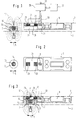
- FIG. 1 schematically shows a window or a door with a stationary frame 1, on which a wing 3 is mounted so that it can pivot about a horizontal and / or a vertical pivot axis.
- the wing 3 is movable about this pivot axis between an open position and a closed position closing the frame opening.
- a drive rod fitting In a peripheral area of the wing 3 is a drive rod fitting, not shown, for example a tilt and turn fitting in the direction of an arrow 5, ie in the circumferential direction of the wing 3, guided.
- a motor drive or a conventional handle olive or the like can be provided for actuating the connecting rod fitting.
- a locking pin 7 is fastened to the connecting rod fitting and can be moved back and forth together with the connecting rod fitting in the direction of arrow 5.
- the bolt pin 7 is assigned a bolt engagement element 9 (striking plate element) which is fixed to the frame 1 and has a bolt engagement recess 11 which is open on one side to the peripheral surface of the wing 3 and in the circumferential direction.
- the locking pin 7 can between the unlocked position shown in FIGS. 1 and 2, in which it is located outside the locking engagement recess 11, and a locked position shown in FIG. 3, in which it is in the locking engagement recess 11 is inserted and the opening movement of the wing 3 prevented, adjusted.
- the locking arrangement is conventional, and it goes without saying that the connecting rod fitting and the locking pin can also be guided on the frame 1, while the locking engagement element 9 can be arranged stationary on the wing 3.
- the locking pin 7 can also be connected in a stationary manner to the frame 1 or the sash 3, while the locking engagement element 9 can be guided to be movable in the circumferential direction on the other part of the window or the door.
- a permanent magnet 15 is fastened in a recess 13 in the locking pin substantially flush.
- the magnetic axis of the permanent magnet 15 extends approximately perpendicular to the circumferential direction and approximately parallel to the plane of the in the illustrated embodiment Wing 3.
- a chamber 21 of the bolt engagement element consisting of non-magnetic material, which at least partially overlaps with the bolt engagement recess 11 at least partially, here essentially completely overlapping in the circumferential direction of the frame 1 and is separated from the bolt engagement recess 11 by a partition 19, and is only open to the frame 1 9 are attached at a distance in the circumferential direction of the frame 1 and thus in the direction of displacement of the locking bolt 7, two magnetic field sensors 23, for example two Hall elements.
- the magnetic field sensors 23 are arranged so that they primarily respond to the magnetic field components running in the direction of the magnetic axis of the permanent magnet 7 and each deliver an output signal that is a measure of the size of this field strength component at the location of the respective magnetic field sensor 23.
- An evaluation circuit 25 is connected to the two magnetic field sensors 23 and compares the output signal of each of the two magnetic field sensors separately with a pair of reference variables.
- the reference quantity pairs define a signal window for each of the two magnetic field sensors 23, which is dimensioned such that the output signals of each of the two magnetic field sensors 23 lie within the signal window when the locking pin 7 and then the permanent magnet 15 are located within the locking engagement recess 11, i.e. the locking arrangement properly is locked (Fig. 3). If the locking pin 7 and thus the permanent magnet 15 are located outside the locking engagement recess 11, the output signals of both magnetic field sensors 23 lie outside the respectively assigned signal window.
- the monitoring circuit 25 delivers at an output 27 a monitoring signal signaling the locking state when both magnetic field sensors 23 emit output signals lying within the signal window.
- the monitoring circuit 25 delivers a monitoring signal signaling the unlocking state if at least one of the two magnetic field sensors 23 delivers an output signal lying outside the signal window.
- the magnetic field sensors 23 are generally asymmetrical to the main magnetic axis of the permanent magnet 15, the magnetic field strength components to which they respond in the locked state are of different sizes. Accordingly, the absolute values of the signal windows and, if appropriate, their width are selected differently. In spite of the fact that only a single permanent magnet 15 is used, a high degree of security against manipulation can be achieved in this way, since the field strength values lying in both signal windows are extremely difficult to simulate.
- the two magnetic field sensors 23 lie in a common plane parallel to the circumferential direction and perpendicular to the plane of the wing 3.
- the two magnetic field sensors 23 can, however, also lie in different planes. Although the arrangement shown with measuring directions parallel to one another are preferred, the measuring directions can nevertheless be inclined to one another.
- the monitoring circuit 25 is assigned a data memory 29 in which the reference variables are stored.
- the reference variables are written into the data memory 29 in an initialization phase of the monitoring circuit 25 after the locking arrangement has been installed. In the initialization phase, the wing 3 is closed and the locking arrangement is locked by inserting the locking pin 7 into the locking engagement recess 11.
- the monitoring circuit 25 determines the reference variables on the basis of the output signals supplied by the magnetic field sensors 23 and writes them into the data memory 29.
- the reference variables can be signals directly comparable with the output signals of the magnetic field sensors 23; it goes without saying that the output signals of the magnetic field sensors may also be processed, in particular digitized, if necessary can be. Both reference values of each signal window can be defined separately and written into the data memory 29; However, it is also conceivable to only define and save a reference variable and to use this reference variable to specify the limits of the signal window during monitoring.
- the monitoring circuit 25 checks the locking state in two successive monitoring cycles. In a first monitoring cycle, the magnetic field detected by the magnetic field sensors 23 is determined exclusively by the permanent magnet 15 of the locking pin 7. In a second monitoring cycle, the monitoring circuit 25 changes the spatial distribution of the magnetic field of the permanent magnet 15 and thus the magnetic field strength components at the location of the two magnetic field sensors 23 by energizing an electromagnet 31 arranged in the vicinity of the locking engagement recess 11 monitors how this above for the case of the magnetic field provided exclusively by the permanent magnet 15. It goes without saying that the variants explained there in connection can also be used here.
- the main magnetic axis of the electromagnet 31 is inclined to the main magnetic axis of the permanent magnet 15, here perpendicular to it. It goes without saying that the electromagnet 31 may be omitted if the second monitoring cycle is to be dispensed with.
- the bolt engagement element 9, the magnetic field sensors 23 and possibly the electromagnet 31 form a common structural unit in order to facilitate assembly.
- a frame bore is also indicated at 33, through which the electrical components of the structural unit can be connected to the monitoring circuit 25.
- the monitoring circuit 25 can optionally be integrated into the structural unit; however, it can also, at least with some of its components, be part of another circuit, for example a monitoring center or the like, to which further monitoring sensors or the like, possibly also other windows or doors, can be connected.
- a change in the spatial distribution of the magnetic field at the location of the magnetic field sensors 23 can result, for example, from aging of the permanent magnet 15 or from changes in the adjustment of the wing 3 relative to the frame 1.
- the magnetic field strength components at the location of the magnetic field sensors 23 can also change to such an extent that, despite a mechanically properly locked locking arrangement, they signal an unlocked state in relation to the originally stored reference quantities or, in the unlocked state, they indicate a locked state.
- the monitoring circuit 25 comprises drift correction means, the reference values stored in the memory 29 in the event of a drift-like slow change in the size of the output signals of the magnetic field sensors 23 follow the field strength component then detected.
- a time average of the output signals of the individual magnetic field sensors 23 can be formed and the deviation of this mean value from the stored reference values can be used to identify and compensate for the drift.
- the drift correction can also be carried out in such a way that if the output signal of the individual magnetic field sensor 23 assigned to the locked state deviates from the reference variable, the reference variable is corrected in the direction of the deviation by a predetermined proportion of the deviation or by a step. The size of the change then determines the rate at which the reference size follows the deviation.
Landscapes
- Engineering & Computer Science (AREA)
- Mechanical Engineering (AREA)
- Burglar Alarm Systems (AREA)
- Lock And Its Accessories (AREA)
Applications Claiming Priority (2)
| Application Number | Priority Date | Filing Date | Title |
|---|---|---|---|
| DE1995118527 DE19518527A1 (de) | 1995-05-19 | 1995-05-19 | Überwachbare Verriegelungsanordnung für ein Fenster oder eine Türe oder dergleichen |
| DE19518527 | 1995-05-19 |
Publications (2)
| Publication Number | Publication Date |
|---|---|
| EP0743410A2 true EP0743410A2 (fr) | 1996-11-20 |
| EP0743410A3 EP0743410A3 (fr) | 1998-03-11 |
Family
ID=7762418
Family Applications (1)
| Application Number | Title | Priority Date | Filing Date |
|---|---|---|---|
| EP96107943A Withdrawn EP0743410A3 (fr) | 1995-05-19 | 1996-05-17 | Dispositif de verrouillage contrÔlé pour portes, fenêtres et similaires |
Country Status (2)
| Country | Link |
|---|---|
| EP (1) | EP0743410A3 (fr) |
| DE (1) | DE19518527A1 (fr) |
Cited By (19)
| Publication number | Priority date | Publication date | Assignee | Title |
|---|---|---|---|---|
| EP0924374A3 (fr) * | 1997-12-19 | 2007-10-03 | Esco Metallbaubeschlag-Handel GmbH | Dispositif de surveillance, en particulier pour fenêtre ou système à ouverture et fermeture similaire |
| WO2015140078A1 (fr) * | 2014-03-18 | 2015-09-24 | Gretsch-Unitas GmbH Baubeschläge | Agencement de porte équipé d'un dispositif de verrouillage entraîné par moteur |
| WO2016012520A1 (fr) * | 2014-07-22 | 2016-01-28 | Mighton Products Limited | Système de capteur d'état de fenêtre |
| EP3118402A1 (fr) * | 2015-07-13 | 2017-01-18 | PaX AG | Dormant de porte ou de fenetre |
| DE102015011299A1 (de) | 2015-09-02 | 2017-03-02 | Siegenia-Aubi Kg | Anordnung zur Verschlussüberwachung |
| WO2018055398A1 (fr) * | 2016-09-23 | 2018-03-29 | Giovanni Laporta | Système de détection de l'état d'un ensemble fenêtre ou porte |
| EP3309333A1 (fr) * | 2016-10-15 | 2018-04-18 | PaX AG | Système comprenant un châssis dormant destiné à loger un cadre de vantail |
| US10027503B2 (en) * | 2013-12-11 | 2018-07-17 | Echostar Technologies International Corporation | Integrated door locking and state detection systems and methods |
| EP3342964A3 (fr) * | 2016-12-29 | 2018-08-22 | SCHÜCO International KG | Dispositif de surveillance formant cadre pour fenêtres ou pour portes et fenêtre ou porte dotées du dispositif de surveillance formant cadre |
| US10060644B2 (en) | 2015-12-31 | 2018-08-28 | Echostar Technologies International Corporation | Methods and systems for control of home automation activity based on user preferences |
| US10073428B2 (en) | 2015-12-31 | 2018-09-11 | Echostar Technologies International Corporation | Methods and systems for control of home automation activity based on user characteristics |
| US10091017B2 (en) | 2015-12-30 | 2018-10-02 | Echostar Technologies International Corporation | Personalized home automation control based on individualized profiling |
| US10101717B2 (en) | 2015-12-15 | 2018-10-16 | Echostar Technologies International Corporation | Home automation data storage system and methods |
| US10200752B2 (en) | 2013-12-16 | 2019-02-05 | DISH Technologies L.L.C. | Methods and systems for location specific operations |
| US10294600B2 (en) | 2016-08-05 | 2019-05-21 | Echostar Technologies International Corporation | Remote detection of washer/dryer operation/fault condition |
| US10550601B2 (en) * | 2017-08-03 | 2020-02-04 | Schlage Lock Company Llc | Method and apparatus to determine a condition of a door |
| EP3539094B1 (fr) | 2016-11-10 | 2020-09-23 | Delta Dore | Dispositif et procede de detection de la position d'un dispositif de mise d'une fenetre dans au moins trois etats differents |
| EP3767059A1 (fr) * | 2019-07-17 | 2021-01-20 | Somfy Activites SA | Détecteur de position d'un pion pour une huisserie à ouvrant pivotant, et procédé de détection |
| EP3828843A1 (fr) * | 2019-11-28 | 2021-06-02 | dormakaba Schweiz AG | Système de capteur |
Families Citing this family (15)
| Publication number | Priority date | Publication date | Assignee | Title |
|---|---|---|---|---|
| DE19815768C2 (de) * | 1998-04-08 | 2000-11-30 | Richard Ross | Kippfensterverriegelung einer Objektsicherungsanlage |
| DE19916118C2 (de) * | 1999-04-09 | 2001-03-15 | Fuss Fritz Gmbh & Co | Vorrichtung zur Verschlußüberwachung einer Verriegelungseinrichtung, insbesondere für Türen und Fenster |
| DE10246642B4 (de) * | 2002-10-07 | 2004-12-30 | Gantner Electronic Gmbh | Elektromechanisches Schloss mit Schutz gegen Manipulation |
| DE102005018826B3 (de) * | 2005-04-22 | 2006-10-05 | Robert Seuffer Gmbh & Co. Kg | Vorrichtung zur Erfassung der Position eines Schließelements, insbesondere eines Fensters oder einer Tür |
| DE102005046868A1 (de) * | 2005-09-30 | 2007-04-19 | Edscha Ag | Türfeststellvorrichtung |
| DE102005000182A1 (de) | 2005-12-13 | 2007-06-21 | Aug. Winkhaus Gmbh & Co. Kg | Überwachbare Verriegelungsanordnung für ein Fenster, eine Türe oder dergleichen und Verfahren zum Betrieb einer solchen Verriegelungsanordnung |
| DE102008017479A1 (de) | 2008-04-03 | 2009-10-15 | Moresens Gmbh | Vorrichtung zur magnetischen Positionsüberwachung |
| DE102008001194A1 (de) | 2008-04-15 | 2009-10-22 | Aug. Winkhaus Gmbh & Co. Kg | Überwachungseinrichtung eines Treibstangenbeschlages eines Fensters |
| DE102008047194A1 (de) * | 2008-09-15 | 2010-04-15 | ABUS August Bremicker Söhne KG | Verriegelungseinheit für Fenster- oder Türflügel |
| GB2505003A (en) * | 2012-08-18 | 2014-02-19 | Mark Gray | Fenestration alarm contact sensor for determining a locked and unlocked configuration |
| DE202014102708U1 (de) * | 2014-06-12 | 2015-09-15 | Baugruppentechnik Pollmeier Gmbh | Verriegelungssystem |
| DE202014009713U1 (de) | 2014-12-10 | 2015-01-30 | Kfv Karl Fliether Gmbh & Co. Kg | Magnetanordnung |
| DE102016107868B3 (de) * | 2016-04-28 | 2017-05-11 | Insta Gmbh | Vorrichtung zur Lageermittlung eines Magneten |
| DE102016123574A1 (de) | 2016-12-06 | 2018-06-07 | Maco Technologie Gmbh | Sicherungsvorrichtung |
| DE102023120327A1 (de) * | 2023-07-31 | 2025-02-06 | Safetec Solution AG | SCHLIEßEINRICHTUNG SOWIE SICHERHEITSANLAGE UND VERFAHREN MIT DER SCHLIEßEINRICHTUNG |
Family Cites Families (17)
| Publication number | Priority date | Publication date | Assignee | Title |
|---|---|---|---|---|
| DE2708938A1 (de) * | 1977-03-02 | 1978-09-07 | Bbc Brown Boveri & Cie | Sicherungseinrichtung |
| DE2813029A1 (de) * | 1978-03-23 | 1979-09-27 | Siemens Ag | Ueberwachungseinrichtung fuer ein tuerschloss |
| DE3316010A1 (de) * | 1983-05-03 | 1985-01-10 | Felten & Guilleaume GmbH, 5000 Köln | Verfahren zum ueberwachen eines im wesentlichen geschlossenen raumes |
| GB8322957D0 (en) * | 1983-08-26 | 1983-09-28 | Securistyle Ltd | Door/window fasteners |
| DE3333497A1 (de) * | 1983-09-16 | 1985-04-18 | Vdo Adolf Schindling Ag, 6000 Frankfurt | Positionsgeber mit mindestens einem hall-schaltelement |
| FR2596094B1 (fr) * | 1986-03-18 | 1991-12-06 | Jouan | Systeme de detection de la fermeture imparfaite des portes d'une enceinte a portes multiples |
| DE3615173A1 (de) * | 1986-05-05 | 1987-11-12 | Fuss Fritz Gmbh & Co | Blockschloss |
| DE3632367C1 (de) * | 1986-09-24 | 1988-02-18 | Heinrich Saelzer | Vorrichtung zur Fernueberwachung der Position und/oder Bewegung einer Absperreinrichtung |
| DE3941086A1 (de) * | 1989-12-13 | 1991-06-20 | Daimler Benz Ag | Kontaktlose tuerkontrolle |
| DE9011016U1 (de) * | 1990-07-25 | 1990-10-11 | Aug. Winkhaus GmbH & Co KG, 4404 Telgte | Verriegelungsvorrichtung für ein Fenster o.dgl. |
| DE9113493U1 (de) * | 1991-10-30 | 1992-01-16 | BKS GmbH, 5620 Velbert | Vorrichtung zur Überwachung des Schließeingriffs von Treibriegelstangen, insbesondere an Treibstangenschlössern |
| DE4204509A1 (de) * | 1992-02-15 | 1993-08-19 | Merk Gmbh Telefonbau Fried | Elektronische ueberwachung von eingangstueren |
| IT229415Y1 (it) * | 1992-02-26 | 1998-07-02 | Conforti Spa | Dispositivo di controllo a distanza per porte di sicurezza e simili |
| FR2698656B1 (fr) * | 1992-12-02 | 1995-01-20 | Jacques Lewiner | Perfectionnements aux dispositifs pour détecter la position engagée d'un pêne. |
| DE4318518C1 (de) * | 1993-06-03 | 1994-09-01 | Fuss Fritz Gmbh & Co | Türüberwachungsvorrichtung |
| DE4438168A1 (de) * | 1993-10-30 | 1995-05-04 | Aeg Sensorsysteme Gmbh | Schließeinrichtung mit einem Schloß und Beschlägen für Haus- und Wohnungstüren |
| DE4337685C2 (de) * | 1993-11-04 | 2003-06-26 | Winkhaus Fa August | Meldeeinrichtungs-Nachrüstsatz für eine Verriegelungseinrichtung für ein Fenster oder dergleichen |
-
1995
- 1995-05-19 DE DE1995118527 patent/DE19518527A1/de not_active Withdrawn
-
1996
- 1996-05-17 EP EP96107943A patent/EP0743410A3/fr not_active Withdrawn
Cited By (26)
| Publication number | Priority date | Publication date | Assignee | Title |
|---|---|---|---|---|
| EP0924374A3 (fr) * | 1997-12-19 | 2007-10-03 | Esco Metallbaubeschlag-Handel GmbH | Dispositif de surveillance, en particulier pour fenêtre ou système à ouverture et fermeture similaire |
| US10027503B2 (en) * | 2013-12-11 | 2018-07-17 | Echostar Technologies International Corporation | Integrated door locking and state detection systems and methods |
| US10200752B2 (en) | 2013-12-16 | 2019-02-05 | DISH Technologies L.L.C. | Methods and systems for location specific operations |
| US11109098B2 (en) | 2013-12-16 | 2021-08-31 | DISH Technologies L.L.C. | Methods and systems for location specific operations |
| US10487538B2 (en) | 2014-03-18 | 2019-11-26 | Gretsch-Unitas Gmbh Baubeschlaege | Door arrangement having a motor-driven locking device |
| WO2015140078A1 (fr) * | 2014-03-18 | 2015-09-24 | Gretsch-Unitas GmbH Baubeschläge | Agencement de porte équipé d'un dispositif de verrouillage entraîné par moteur |
| WO2016012520A1 (fr) * | 2014-07-22 | 2016-01-28 | Mighton Products Limited | Système de capteur d'état de fenêtre |
| EP3118402A1 (fr) * | 2015-07-13 | 2017-01-18 | PaX AG | Dormant de porte ou de fenetre |
| EP3159464A1 (fr) | 2015-09-02 | 2017-04-26 | Siegenia-Aubi KG | Systeme de surveillance de fermeture |
| DE102015011299A1 (de) | 2015-09-02 | 2017-03-02 | Siegenia-Aubi Kg | Anordnung zur Verschlussüberwachung |
| US10101717B2 (en) | 2015-12-15 | 2018-10-16 | Echostar Technologies International Corporation | Home automation data storage system and methods |
| US10091017B2 (en) | 2015-12-30 | 2018-10-02 | Echostar Technologies International Corporation | Personalized home automation control based on individualized profiling |
| US10060644B2 (en) | 2015-12-31 | 2018-08-28 | Echostar Technologies International Corporation | Methods and systems for control of home automation activity based on user preferences |
| US10073428B2 (en) | 2015-12-31 | 2018-09-11 | Echostar Technologies International Corporation | Methods and systems for control of home automation activity based on user characteristics |
| US10294600B2 (en) | 2016-08-05 | 2019-05-21 | Echostar Technologies International Corporation | Remote detection of washer/dryer operation/fault condition |
| WO2018055398A1 (fr) * | 2016-09-23 | 2018-03-29 | Giovanni Laporta | Système de détection de l'état d'un ensemble fenêtre ou porte |
| US11473337B2 (en) | 2016-09-23 | 2022-10-18 | Giovanni Laporta | System for detecting the status of a window or door assembly |
| AU2017332835B2 (en) * | 2016-09-23 | 2023-08-17 | Giovanni Laporta | System for detecting the status of a window or door assembly |
| EP3516137B1 (fr) | 2016-09-23 | 2024-08-21 | Giovanni Laporta | Système de détection de l'état d'un ensemble fenêtre ou porte |
| EP3309333A1 (fr) * | 2016-10-15 | 2018-04-18 | PaX AG | Système comprenant un châssis dormant destiné à loger un cadre de vantail |
| EP3539094B1 (fr) | 2016-11-10 | 2020-09-23 | Delta Dore | Dispositif et procede de detection de la position d'un dispositif de mise d'une fenetre dans au moins trois etats differents |
| EP3342964A3 (fr) * | 2016-12-29 | 2018-08-22 | SCHÜCO International KG | Dispositif de surveillance formant cadre pour fenêtres ou pour portes et fenêtre ou porte dotées du dispositif de surveillance formant cadre |
| US10550601B2 (en) * | 2017-08-03 | 2020-02-04 | Schlage Lock Company Llc | Method and apparatus to determine a condition of a door |
| EP3767059A1 (fr) * | 2019-07-17 | 2021-01-20 | Somfy Activites SA | Détecteur de position d'un pion pour une huisserie à ouvrant pivotant, et procédé de détection |
| FR3098837A1 (fr) * | 2019-07-17 | 2021-01-22 | Somfy Activites Sa | Détecteur de position d’un pion pour une huisserie à ouvrant pivotant, et procédé de détection |
| EP3828843A1 (fr) * | 2019-11-28 | 2021-06-02 | dormakaba Schweiz AG | Système de capteur |
Also Published As
| Publication number | Publication date |
|---|---|
| DE19518527A1 (de) | 1996-11-21 |
| EP0743410A3 (fr) | 1998-03-11 |
Similar Documents
| Publication | Publication Date | Title |
|---|---|---|
| EP0743410A2 (fr) | Dispositif de verrouillage contrÔlé pour portes, fenêtres et similaires | |
| DE29519486U1 (de) | Vorrichtung zur Überwachung des Fenster-Verschlußzustands eines Öffnungs-Abdeckelements und Öffnungs-Abdeckelement mit einer derartigen Verschlußzustandsüberwachung | |
| EP0445398A2 (fr) | Tourniquet de contrôle pour passages de personnes | |
| EP0763644B2 (fr) | Fenêtre/porte avec positions de verrouillage entre le battant pivotant et/ou basculant et le cadre fixe | |
| DE102005018826B3 (de) | Vorrichtung zur Erfassung der Position eines Schließelements, insbesondere eines Fensters oder einer Tür | |
| DE102010018566B4 (de) | Zustandsdetektionsvorrichtung für eine Schließvorrichtung und eine solche umfassende Schließvorrichtung | |
| EP1058764A1 (fr) | Dispositif de fermeture pour porte d'armoire de commande, habillage de machine ou similaire | |
| EP0887495A1 (fr) | Système d'accouplement pour dispositifs de fermeture électroniques | |
| DE69926455T2 (de) | Schlüsselsicherheitsschalter | |
| EP3004717A1 (fr) | Porte d'ascenseur pourvue d'un contacteur | |
| DE19938378A1 (de) | Vorrichtung zum Öffnen und Verschließen einer Öffnung in einer Wandung mittels einer Schiebetür | |
| DE102008062230A1 (de) | Meßanordnung einer Funktionseinheit in einem Kraftfahrzeug | |
| EP3498960A1 (fr) | Dispositif de verrouillage pour une porte, en particulier une porte coulissante | |
| EP1260657B1 (fr) | Dispositif de serrure | |
| DE4031348A1 (de) | Sicherheitsschalter | |
| DE202019106083U1 (de) | Sicherheitsmodul und modulare Sicherheitsalarmgriff-Vorrichtung zur Montage an einem beweglichen Tür- oder Fensterrahmen | |
| DE29923398U1 (de) | Schließsystem für Möbel | |
| DE202013005835U1 (de) | Schließvorrichtung für Türen, Fenster oder dergleichen | |
| EP0844356B1 (fr) | Dispositif pour la commande d'une fenêtre | |
| DE102008034340A1 (de) | Vorrichtung zum Schließen einer Tür | |
| EP0135805B1 (fr) | Serrure pour porte | |
| DE9117070U1 (de) | Ventileinrichtung | |
| DE9212791U1 (de) | Vorrichtung zum Ver- und Entriegeln einer Tür in einem verfahrbaren Trennwandelement | |
| DE4413904A1 (de) | Stelleinrichtung für eine Zentralverriegelung mit überrastbaren Federnocken | |
| DE19537929A1 (de) | Verschließbares Schrankelement |
Legal Events
| Date | Code | Title | Description |
|---|---|---|---|
| PUAI | Public reference made under article 153(3) epc to a published international application that has entered the european phase |
Free format text: ORIGINAL CODE: 0009012 |
|
| AK | Designated contracting states |
Kind code of ref document: A2 Designated state(s): AT BE CH DE DK ES FI FR GB IT LI NL SE |
|
| PUAL | Search report despatched |
Free format text: ORIGINAL CODE: 0009013 |
|
| AK | Designated contracting states |
Kind code of ref document: A3 Designated state(s): AT BE CH DE DK ES FI FR GB IT LI NL SE |
|
| 17P | Request for examination filed |
Effective date: 19980515 |
|
| STAA | Information on the status of an ep patent application or granted ep patent |
Free format text: STATUS: THE APPLICATION HAS BEEN WITHDRAWN |
|
| 18W | Application withdrawn |
Withdrawal date: 19990813 |