EP0743457B1 - Kreiselpumpe mit Ansaugpumpe mit flexiblen Schaufeln - Google Patents
Kreiselpumpe mit Ansaugpumpe mit flexiblen Schaufeln Download PDFInfo
- Publication number
- EP0743457B1 EP0743457B1 EP96850092A EP96850092A EP0743457B1 EP 0743457 B1 EP0743457 B1 EP 0743457B1 EP 96850092 A EP96850092 A EP 96850092A EP 96850092 A EP96850092 A EP 96850092A EP 0743457 B1 EP0743457 B1 EP 0743457B1
- Authority
- EP
- European Patent Office
- Prior art keywords
- impeller
- rotary
- liquid pump
- chamber
- pump
- Prior art date
- Legal status (The legal status is an assumption and is not a legal conclusion. Google has not performed a legal analysis and makes no representation as to the accuracy of the status listed.)
- Expired - Lifetime
Links
- 230000037452 priming Effects 0.000 title claims description 20
- 239000007788 liquid Substances 0.000 claims description 34
- 239000012530 fluid Substances 0.000 claims description 8
- 238000005086 pumping Methods 0.000 claims description 6
- 238000007599 discharging Methods 0.000 claims description 4
- 230000001939 inductive effect Effects 0.000 claims 1
- 238000001816 cooling Methods 0.000 description 4
- 239000004576 sand Substances 0.000 description 4
- 102000010637 Aquaporins Human genes 0.000 description 1
- 108010063290 Aquaporins Proteins 0.000 description 1
- 229920002457 flexible plastic Polymers 0.000 description 1
- 238000010348 incorporation Methods 0.000 description 1
- 238000004519 manufacturing process Methods 0.000 description 1
- 230000013011 mating Effects 0.000 description 1
- 230000037361 pathway Effects 0.000 description 1
- 238000009987 spinning Methods 0.000 description 1
Images




Classifications
-
- F—MECHANICAL ENGINEERING; LIGHTING; HEATING; WEAPONS; BLASTING
- F04—POSITIVE - DISPLACEMENT MACHINES FOR LIQUIDS; PUMPS FOR LIQUIDS OR ELASTIC FLUIDS
- F04C—ROTARY-PISTON, OR OSCILLATING-PISTON, POSITIVE-DISPLACEMENT MACHINES FOR LIQUIDS; ROTARY-PISTON, OR OSCILLATING-PISTON, POSITIVE-DISPLACEMENT PUMPS
- F04C5/00—Rotary-piston machines or pumps with the working-chamber walls at least partly resiliently deformable
-
- F—MECHANICAL ENGINEERING; LIGHTING; HEATING; WEAPONS; BLASTING
- F04—POSITIVE - DISPLACEMENT MACHINES FOR LIQUIDS; PUMPS FOR LIQUIDS OR ELASTIC FLUIDS
- F04C—ROTARY-PISTON, OR OSCILLATING-PISTON, POSITIVE-DISPLACEMENT MACHINES FOR LIQUIDS; ROTARY-PISTON, OR OSCILLATING-PISTON, POSITIVE-DISPLACEMENT PUMPS
- F04C11/00—Combinations of two or more machines or pumps, each being of rotary-piston or oscillating-piston type; Pumping installations
- F04C11/005—Combinations of two or more machines or pumps, each being of rotary-piston or oscillating-piston type; Pumping installations of dissimilar working principle
-
- F—MECHANICAL ENGINEERING; LIGHTING; HEATING; WEAPONS; BLASTING
- F04—POSITIVE - DISPLACEMENT MACHINES FOR LIQUIDS; PUMPS FOR LIQUIDS OR ELASTIC FLUIDS
- F04D—NON-POSITIVE-DISPLACEMENT PUMPS
- F04D9/00—Priming; Preventing vapour lock
- F04D9/04—Priming; Preventing vapour lock using priming pumps; using booster pumps to prevent vapour-lock
- F04D9/041—Priming; Preventing vapour lock using priming pumps; using booster pumps to prevent vapour-lock the priming pump having evacuating action
Definitions
- This invention pertains to rotary liquid pumps, such as vortex-type cooling pumps used, for example, with marine diesel engines.
- a rotary, liquid pump comprising a housing; a shaft journaled in said housing; a pair of impellers mounted on said shaft, in spaced apart disposition, for rotation in common with said shaft; means for admitting liquid to said housing; means for discharging impelled liquid from said housing; of said impellers a first having rigid vanes and a second flexible vanes; wherein said second impeller rotates in a chamber having an inner circumferential surface provided with cusps at a plurality of locations; said chamber being provided with side walls which cooperate with said surface to define a pumping chamber; which side walls are provided with inlet ports and outlet ports respectively for admitting and discharging fluid.
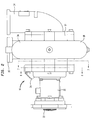
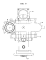
- the novel, rotary, liquid pump 10 comprises a housing 12.
- the housing 12 has an inlet conduit 14 bolted thereto, and an outlet conduit 16 extending therefrom, the same being integral with the main body 18 of the housing 12.
- a distance piece 20 is fastened to the housing 12 and, at the outermost end thereof, bares an input gear 22.
- the gear 22 is disposed for engagement thereof with a prime mover (not shown).
- the housing 12 further has an angled, short cylinder 24 extending therefrom, the same comprising a second outlet conduit. Installed in the outermost end of the outlet 16 is a check valve 28 of the flapper type.
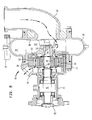
- FIG. 5 shows the inner structures of the pump 10.
- the inlet conduit 14 opens onto the hub 30 of a paddle-wheel-type impeller 32.
- the impeller 32 in this embodiment thereof, has a diameter of approximately six inches, and it is disposed for rotation within a liquid-working chamber 34 which has a diameter of approximately twelve inches.
- the impeller 32 and the vanes 36 thereof are rigid; the vanes 36 are straight, and terminated with flat ends.
- Chamber 34 has parallel, confronting walls 38 and 40, and the lateral edges of the vanes 36 are spaced apart, from the walls, approximately one-eighth of an inch.
- Impeller hub 30 is engaged with a rotary shaft 42, the terminal end of the shaft being threaded and has a nut 44, torqued thereon, which holds a washer 46 and a lock washer 48 fast against the hub 30.
- the shaft 42 and hub 30 have keyways formed therein which receive a key 50 for mating the impeller 32 with the shaft 42 for common rotation therewith.
- the housing 12 Inboard of the chamber 34, the housing 12 has a second chamber 52.
- Chamber 52 is formed by a pair of circular plates 54 and 56 which are set apart, in parallelism, by an intervening ring 58.
- a second impeller 60 is confined within chamber 52, and keyingly engaged with the shaft 42 thereat.
- Impeller 60 has flexible (i.e., rubber) vanes 61, and the impeller width and diameter is such as to give it an intimate fit within the chamber 52; it is rotatable therein with a fine clearance relative to the walls and periphery of chamber 52.
- the impeller 32 is the main pumping element in the pump, whereas impeller 60 is a priming impeller.
- Impeller 60 is double-acting.
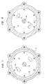
- the plates 54 and 56 as shown in Figures 7 and 8, have pairs of ports formed therein.
- Ports 62 and 64 of plate 54 constitute liquid inlets for the priming impeller 60
- the ports 66 and 68, of plate 56 constitute liquid outlets for the priming impeller 60.
- the impeller 60 primes even under dry (non-liquid) conditions.
- the flapper valve 28, shown in more detail in Figure 6, cooperates with the impeller 60 to create a vacuum pressure in the inlet conduit 14.
- the impeller 60 ingests air, along the arrowed pathway shown in Figure 5, until the vacuum pressure proceeds to draw liquid.
- the pump 10 expels liquid through the priming impeller discharge conduit embodied by the cylinder 24 and through the outlet conduit 16. Discharge pressure is generated by a spinning vortex in the constant velocity chamber 34.
- the pump 10, shown herein to be of the vortex type in this embodiment of the invention is capable of flow rates up to about four hundred gallons of liquid a minute and able to provide cooling of engines of up to approximately 2500 horsepower. It is inordinately efficient; even with the parasitical load of the priming impeller 60, it operates at an efficiency range of approximately fifty to sixty percent. As noted, the pump 10, having the flexible-vane priming impeller 60 will self-prime even when the environment in which it commences to operate is absolutely dry.
- the paddle-wheel type, primary impeller 32 is not encumbered with close clearances in its chamber 34, accordingly it is not notably subject to wear; it can handle sand and debris exceedingly well.
- the priming impeller 60 for having flexible vanes 61, can deal well with sand and other detritus. Radial loading of the impeller 32 is essentially zero; the constant velocity vortex generated about the periphery of the impeller 32 means that the pressure is also equal thereabout. Radial loading of the priming impeller 60 is also essentially zero because of its radial symmetry. Pump 10, then, promises long life in heavy duty for the seals and bearings thereof, and minimum replacements, over time, of the impellers 32 and 60.
- the priming portion of the pump 10 comprising the impeller 60 rotary within the second chamber 52, and having flexible vanes 61, is double-acting (i.e., producing two pumping cycles per revolution), it effectively doubles the flow rate for a given impeller size and, as noted, eliminates radial thrust since all radial forces are balanced.
- the priming portion of the pump 10 would cause a sacrifice in pressure capability but, with this embodiment of the invention, discharge pressure generation for the priming portion is not a requirement. Its discharge is simply routed overboard or to the exhaust system so that back pressure is minimal.
- Prior art, flexible impeller pumps have inlet and discharge ports which are disposed radially of the impeller.
- the inlet ports 62 and 64 in plate 54, and outlet ports 66 and 68 in plate 56 are axially disposed, and provide for an axial flow path through the priming portion of the pump 10.
- This arrangement allows for a continuous cam ring 58; the vanes 61 do not have to pass over any discontinuity in the ring 58.
- impeller life, and vane life are extended significantly.
- this priming pump 70 has an enclosing ring 58 which mounts plates 54 and 56 to either side thereof.
- the ring 58 has an inner circumferential surface 72 which is uninterruptedly continuous.
- the plates 54 and 56 cooperate with the ring 58 to define a pumping chamber 52 therewithin.
- Pump 70 has no radial ports; the inlet ports 62 and 64, as well as the outlet ports 66 and 68 produce an axial flow path through the pump 70.
- Ports 62 and 64, in plate 54 are equally spaced apart, i.e., one hundred and eighty degrees of arc apart, with reference to the rotary axis 74 of the pump 70, and the ports 66 and 68 are also similarly spaced apart. Too, the ports 62 and 64 are spaced apart from ports 66 and 68 ninety degrees of arc.
- inlet ports 62 and 64 are located at approximately forty-five and two hundred and twenty-five degrees of arc, and ports 66 and 68 at approximately three hundred and fifteen, and one hundred and thirty-five degrees of arc, from a vertical reference point 76 constituted by a bolt hole 78. Such positionings cooperate with the inner surface 72 of the pump 70 to derive the most efficient performance of the pump.
- the surface 72 of the ring 58 is novelly defined of a plurality of radii.
- a radius 80, subsisting at the top and bottom of the pump 70, and a shorter radius 82 obtaining at the opposite sides of the surface 72, are drawn from the radial center or axis 74, and a third radius 84, drawn from designated locii at four places offset from the axis or radial center (only one of which is shown) defines portions of the surface 72 which join the surfaces formed by radii 80 and 82. Too, radii 84 define cusps 86 at four locations about the surface 72.
- the cusps 86 comprise means for causing the fingers or vanes 61 to flex outwardly or inwardly, abruptly, as they pass over the cusps and move onto the next-adjacent surfacing.
- the vanes or fingers 61 are given a "bump,” so to speak, to enhance fluid intake and to enhance fluid discharge at these locations.
- finger 88 is greatly bent and is moving upon the cusp 86 thereat, whereas finger 90 has passed the cusp 86 and has swung outwardly to define an enlarged subchamber 92 there which is open to the port 62 to draw a marked quantity of fluid thereinto.
- finger 92 at the other side of the impeller 60, has moved onto the cusp 86 thereat and, as a consequence, has been bent severely causing it to expel its captured fluid into port 66 as it passed thereover; finger 94 which follows will also be forced to squeeze out its contained fluid as it moves onto the cusp 86 there.
Landscapes
- Engineering & Computer Science (AREA)
- Mechanical Engineering (AREA)
- General Engineering & Computer Science (AREA)
- Structures Of Non-Positive Displacement Pumps (AREA)
Claims (12)
- Rotations-Flüssigkeitspumpe mitdadurch gekennzeichnet,einem Gehäuse (12);einer in dem Gehäuse gelagerten Welle (42);einem Paar Laufräder (32 und 60), die im Abstand voneinander jeweils auf der Welle derart angebracht sind, daß sie sich zusammen mit der Welle drehen;einer Einrichtung (14) zum Einlassen von Flüssigkeit in das Gehäuse, undeiner Einrichtung (16) für den Austritt von vorangetriebener Flüssigkeit aus dem Gehäuse;wobei von den Laufrädern ein erstes (32) starre Flügel (36) und ein zweites (60) flexible Flügel (61) aufweist,daß das zweite Laufrad (60) in einer Kammer (52) umläuft, die eine Innenumfangsfläche (72) mit an einer Mehrzahl von Stellen vorgesehenen Scheitelpunkten (86) aufweist,daß die Kammer (52) mit Seitenwänden (54 bzw. 56) versehen ist, die mit der Fläche (72) unter Bildung einer Pumpkammer (52) zusammenwirken,daß die erste Seitenwand (54) mit Einlaßöffnungen (62 bzw. 64) für den axialen Einlaß von Fluid in die Kammer (52) versehen ist, unddaß die zweite Seitenwand (56) mit Auslaßöffnungen (66 bzw. 68) für den Austritt von Fluid axial aus der Kammer (52) versehen ist.
- Rotations-Flüssigkeitspumpe nach Anspruch 1,
dadurch gekennzeichnet, daß die Kammer (52) einen Innenring (58) aufweist, dessen Innenfläche mit den Scheitelpunkten (86) versehen ist. - Rotations-Flüssigkeitspumpe nach Anspruch 2,
dadurch gekennzeichnet, daß die Wände (54 bzw. 56) in austauschbarer Weise an beiden Seiten des Rings (58) angebracht sind. - Rotations-Flüssigkeitspumpe nach Anspruch 1,
dadurch gekennzeichnet, daß die Öffnungen jedes Öffnungspaares (62, 64 bzw. 66, 68) gleichmäßig voneinander beabstandet sind. - Rotations-Flüssigkeitspumpe nach Anspruch 4,
dadurch gekennzeichnet, daß die Öffnungen eines Öffnungspaares relativ zu der Achse (42) in einem Winkel von 90° von dem anderen Öffnungspaar angeordnet sind. - Rotations-Flüssigkeitspumpe nach Anspruch 1,
dadurch gekennzeichnet, daß die Fläche (72) aus einer Mehrzahl von Radien gebildet ist. - Rotations-Flüssigkeitspumpe nach Anspruch 1,
dadurch gekennzeichnet, daß die Umfangsfläche (72) ein radiales Zentrum aufweist und aus einer Mehrzahl von Radien, die von dem Zentrum aus gezogen sind, sowie aus einer Mehrzahl von Radien, die von von dem Zentrum versetzten Stellen aus gezogen sind, gebildet sind. - Rotations-Flüssigkeitspumpe nach Anspruch 1,
dadurch gekennzeichnet, daß die Scheitelpunkte (86) die flexiblen Flügel (61) des Laufrads (60) dazu veranlassen, sich an einer Mehrzahl von Stellen in der Kammer (52) abrupt zu biegen. - Rotations-Flüssigkeitspumpe nach Anspruch 1,
dadurch gekennzeichnet, daß der Auslaß (16) eine mit dem anderen Laufrad (60) zusammenwirkende Einrichtung zum Hervorrufen eines Unterdrucks in der Einlaßeinrichtung (14) aufweist. - Rotations-Flüssigkeitspumpe nach Anspruch 1,
dadurch gekennzeichnet, daß das erste Laufrad (32) in einer Kammer (34) umläuft, die einen gegebenen Außendurchmesser aufweist, und daß das erste Laufrad (32) einen Außendurchmesser aufweist, der etwa die Hälfte des gegebenen Durchmessers beträgt. - Rotations-Flüssigkeitspumpe nach Anspruch 1,
dadurch gekennzeichnet, daß es sich bei dem ersten Laufrad (32) um ein primäres flüssigkeitsbearbeitendes Laufrad handelt und es sich bei dem zweiten Laufrad (60) um ein Ansaug-Laufrad handelt. - Rotations-Flüssigkeitspumpe nach Anspruch 1,
dadurch gekennzeichnet, daß die zweite Kammer (52) eine Einrichtung zum Bewältigen einer axialen Strömung durch diese hindurch aufweist.
Applications Claiming Priority (2)
| Application Number | Priority Date | Filing Date | Title |
|---|---|---|---|
| US08/440,793 US5599171A (en) | 1995-05-15 | 1995-05-15 | Rotary, self-priming, liquip pump, and an impellers and shaft assembly therefor, and a flexible-impeller pump assembly |
| US440793 | 1995-05-15 |
Publications (2)
| Publication Number | Publication Date |
|---|---|
| EP0743457A1 EP0743457A1 (de) | 1996-11-20 |
| EP0743457B1 true EP0743457B1 (de) | 2000-11-29 |
Family
ID=23750206
Family Applications (1)
| Application Number | Title | Priority Date | Filing Date |
|---|---|---|---|
| EP96850092A Expired - Lifetime EP0743457B1 (de) | 1995-05-15 | 1996-05-09 | Kreiselpumpe mit Ansaugpumpe mit flexiblen Schaufeln |
Country Status (4)
| Country | Link |
|---|---|
| US (1) | US5599171A (de) |
| EP (1) | EP0743457B1 (de) |
| JP (2) | JPH08312577A (de) |
| DE (1) | DE69611054T2 (de) |
Families Citing this family (18)
| Publication number | Priority date | Publication date | Assignee | Title |
|---|---|---|---|---|
| GB2320031B (en) * | 1996-12-06 | 2001-05-02 | Stephen Skill | Apparatus and method for growing culture of micro-organisms |
| US6071072A (en) * | 1998-12-02 | 2000-06-06 | Chang; Wan-Te | Self-priming centrifugal pump |
| US6206632B1 (en) | 1999-03-26 | 2001-03-27 | Timothy D. Gallus | Bleed tube for centrifugal pump and method for retrofitting same |
| DK200000278U4 (da) * | 2000-09-20 | 2002-01-11 | Apv Fluid Handling Horsens As | Hygiejnisk selvansugende centrifugalpumpe. |
| SE519641C2 (sv) * | 2001-08-08 | 2003-03-25 | Metso Paper Inc | Kombinerad centrifugal- och vakuumpump för pumpning av massa |
| AU2008219105B2 (en) * | 2007-02-16 | 2013-05-30 | Gojo Industries, Inc. | Flexible impeller pumps for mixing individual components |
| WO2011017708A1 (en) * | 2009-08-07 | 2011-02-10 | Sta-Rite Industries, Llc | Dry run porting system |
| JP5510006B2 (ja) * | 2010-04-01 | 2014-06-04 | セイコーエプソン株式会社 | マイクロポンプ |
| KR101228770B1 (ko) * | 2010-07-21 | 2013-01-31 | 지효근 | 스퍼트 펌프 |
| DE102011078017B3 (de) * | 2011-06-22 | 2012-06-21 | E.G.O. Elektro-Gerätebau GmbH | Pumpe |
| AU2013274079B2 (en) * | 2012-06-14 | 2017-08-31 | Flow Control Llc. | Preventing submersible pump air lock |
| WO2014139578A1 (en) * | 2013-03-14 | 2014-09-18 | Grundfos Holding A/S | Impeller |
| GB201410986D0 (en) * | 2014-06-20 | 2014-08-06 | Marine Flow Ltd | Flexible impeller pump |
| DE102015003224C5 (de) * | 2015-03-13 | 2021-07-15 | Gea Tuchenhagen Gmbh | Selbstansaugende Pumpe |
| GB2547657A (en) * | 2016-02-23 | 2017-08-30 | Barrus E P Ltd | Pump |
| CN107448418B (zh) * | 2017-06-01 | 2019-09-20 | 武汉船用机械有限责任公司 | 一种叶片泵 |
| CN107461367B (zh) * | 2017-07-21 | 2024-06-21 | 上海福慧特泵业制造有限公司 | 一种无接触纳米气泡微泵 |
| WO2021262551A1 (en) * | 2020-06-26 | 2021-12-30 | LeimbachCausey, LLC | Multi-chamber impeller pump |
Family Cites Families (18)
| Publication number | Priority date | Publication date | Assignee | Title |
|---|---|---|---|---|
| US2734457A (en) * | 1956-02-14 | fernstrum | ||
| US2899902A (en) * | 1959-08-18 | Rotary pump impeller | ||
| GB191011818A (en) * | 1909-05-12 | 1911-05-11 | Wilhelm Von Pittler | Improvements in Rotary Fluid Pressure Machines. |
| GB672522A (en) * | 1949-08-19 | 1952-05-21 | Eugene Mayus | Rotary pumps |
| US3082694A (en) * | 1960-05-24 | 1963-03-26 | Ingersoll Rand Co | Self-priming centrifugal pump |
| FR1307316A (fr) * | 1961-09-06 | 1962-10-26 | Nouveau perfectionnement apporté aux pompes rotatives à aubages flexibles | |
| US3163157A (en) * | 1963-09-26 | 1964-12-29 | Crusader Marine Corp | Apparatus for cooling an internal combustion engine |
| US3518028A (en) * | 1968-01-26 | 1970-06-30 | Trw Inc | Power reduction of liquid ring pumps |
| DE2757952C2 (de) * | 1977-12-24 | 1983-02-24 | Sihi Gmbh & Co Kg, 2210 Itzehoe | Selbstansaugende Kreiselpumpe |
| US4392779A (en) * | 1980-05-05 | 1983-07-12 | Brunswick Corporation | Marine drive water pump |
| JPS57113994A (en) * | 1980-12-29 | 1982-07-15 | Yamaha Motor Co Ltd | Rotary pump |
| JPS588292A (ja) * | 1981-07-08 | 1983-01-18 | Tokyo Tatsuno Co Ltd | 自吸式遠心ポンプ |
| JPS6024317U (ja) * | 1983-07-25 | 1985-02-19 | 増田 喜章 | ワンタッチで着脱できる油圧タンク用フィルタ− |
| US4624627A (en) * | 1985-02-22 | 1986-11-25 | Tunks Larry M | Self-priming pump |
| JPS62243979A (ja) * | 1986-04-14 | 1987-10-24 | Sanshin Ind Co Ltd | 船舶推進機の水ポンプ保護装置 |
| JPH036512U (de) * | 1989-06-06 | 1991-01-22 | ||
| JPH06249160A (ja) * | 1993-02-26 | 1994-09-06 | Suzuki Motor Corp | 船外機の冷却水ポンプ構造 |
| JP3122295B2 (ja) * | 1993-12-09 | 2001-01-09 | 株式会社東芝 | 磁気ディスクコントローラの二重化方法 |
-
1995
- 1995-05-15 US US08/440,793 patent/US5599171A/en not_active Expired - Lifetime
-
1996
- 1996-05-09 EP EP96850092A patent/EP0743457B1/de not_active Expired - Lifetime
- 1996-05-09 DE DE69611054T patent/DE69611054T2/de not_active Expired - Fee Related
- 1996-05-14 JP JP8119069A patent/JPH08312577A/ja active Pending
-
1999
- 1999-11-11 JP JP1999008608U patent/JP3068887U/ja not_active Expired - Lifetime
Also Published As
| Publication number | Publication date |
|---|---|
| JPH08312577A (ja) | 1996-11-26 |
| JP3068887U (ja) | 2000-05-26 |
| DE69611054D1 (de) | 2001-01-04 |
| US5599171A (en) | 1997-02-04 |
| DE69611054T2 (de) | 2001-06-13 |
| EP0743457A1 (de) | 1996-11-20 |
Similar Documents
| Publication | Publication Date | Title |
|---|---|---|
| US5599171A (en) | Rotary, self-priming, liquip pump, and an impellers and shaft assembly therefor, and a flexible-impeller pump assembly | |
| US3468260A (en) | Rotary pump with axially movable radial vanes | |
| US4132504A (en) | Liquid ring pump | |
| US3644061A (en) | Pump apparatus | |
| EP0560466A3 (de) | Zentrifugalblutpumpe und Motorantrieb | |
| CA2013132A1 (en) | Pump for and method of separating gas from a fluid to be pumped | |
| US4273515A (en) | Liquid ring pump | |
| KR101072855B1 (ko) | 진공 강 자흡식 펌프 | |
| US5660536A (en) | High capacity simplified sea water pump | |
| US3795459A (en) | Pitot pump with slotted inlet passages in rotor case | |
| US2659313A (en) | Rotary pump | |
| US2734457A (en) | fernstrum | |
| US4406121A (en) | Rotary fluid device | |
| US3395649A (en) | Impeller construction | |
| US4826402A (en) | High-capacity centrifugal pump | |
| KR100951430B1 (ko) | 자흡식 터보펌프 | |
| US5219271A (en) | High capacity, high efficiency pump | |
| US5803713A (en) | Multi-stage liquid ring vacuum pump-compressor | |
| EP1505301A2 (de) | Selbstansaugende Kreiselpumpe | |
| KR100540381B1 (ko) | 자흡식 펌프용 임펠러 | |
| US20020119065A1 (en) | Cartridge vane pump having enhanced cold start performance | |
| JP2587942B2 (ja) | ポンプ | |
| US3582235A (en) | Rotary pump | |
| JPS5824637B2 (ja) | 自吸式ポンプ | |
| CN220646300U (zh) | 一种可调节出水口方向的泵 |
Legal Events
| Date | Code | Title | Description |
|---|---|---|---|
| PUAI | Public reference made under article 153(3) epc to a published international application that has entered the european phase |
Free format text: ORIGINAL CODE: 0009012 |
|
| AK | Designated contracting states |
Kind code of ref document: A1 Designated state(s): DE FR GB |
|
| 17P | Request for examination filed |
Effective date: 19970429 |
|
| 17Q | First examination report despatched |
Effective date: 19991014 |
|
| GRAG | Despatch of communication of intention to grant |
Free format text: ORIGINAL CODE: EPIDOS AGRA |
|
| GRAG | Despatch of communication of intention to grant |
Free format text: ORIGINAL CODE: EPIDOS AGRA |
|
| GRAH | Despatch of communication of intention to grant a patent |
Free format text: ORIGINAL CODE: EPIDOS IGRA |
|
| GRAH | Despatch of communication of intention to grant a patent |
Free format text: ORIGINAL CODE: EPIDOS IGRA |
|
| GRAA | (expected) grant |
Free format text: ORIGINAL CODE: 0009210 |
|
| AK | Designated contracting states |
Kind code of ref document: B1 Designated state(s): DE FR GB |
|
| REF | Corresponds to: |
Ref document number: 69611054 Country of ref document: DE Date of ref document: 20010104 |
|
| ET | Fr: translation filed | ||
| PLBE | No opposition filed within time limit |
Free format text: ORIGINAL CODE: 0009261 |
|
| STAA | Information on the status of an ep patent application or granted ep patent |
Free format text: STATUS: NO OPPOSITION FILED WITHIN TIME LIMIT |
|
| 26N | No opposition filed | ||
| REG | Reference to a national code |
Ref country code: GB Ref legal event code: IF02 |
|
| PGFP | Annual fee paid to national office [announced via postgrant information from national office to epo] |
Ref country code: GB Payment date: 20040505 Year of fee payment: 9 |
|
| PGFP | Annual fee paid to national office [announced via postgrant information from national office to epo] |
Ref country code: FR Payment date: 20040519 Year of fee payment: 9 |
|
| PGFP | Annual fee paid to national office [announced via postgrant information from national office to epo] |
Ref country code: DE Payment date: 20040630 Year of fee payment: 9 |
|
| PG25 | Lapsed in a contracting state [announced via postgrant information from national office to epo] |
Ref country code: GB Free format text: LAPSE BECAUSE OF NON-PAYMENT OF DUE FEES Effective date: 20050509 |
|
| PG25 | Lapsed in a contracting state [announced via postgrant information from national office to epo] |
Ref country code: DE Free format text: LAPSE BECAUSE OF NON-PAYMENT OF DUE FEES Effective date: 20051201 |
|
| GBPC | Gb: european patent ceased through non-payment of renewal fee |
Effective date: 20050509 |
|
| PG25 | Lapsed in a contracting state [announced via postgrant information from national office to epo] |
Ref country code: FR Free format text: LAPSE BECAUSE OF NON-PAYMENT OF DUE FEES Effective date: 20060131 |
|
| REG | Reference to a national code |
Ref country code: FR Ref legal event code: ST Effective date: 20060131 |