EP0747650A1 - Einlass- und Auslassverbinder für Wärmetauscher - Google Patents
Einlass- und Auslassverbinder für Wärmetauscher Download PDFInfo
- Publication number
- EP0747650A1 EP0747650A1 EP96108950A EP96108950A EP0747650A1 EP 0747650 A1 EP0747650 A1 EP 0747650A1 EP 96108950 A EP96108950 A EP 96108950A EP 96108950 A EP96108950 A EP 96108950A EP 0747650 A1 EP0747650 A1 EP 0747650A1
- Authority
- EP
- European Patent Office
- Prior art keywords
- heat exchanger
- union
- header pipe
- brazed
- fluid passage
- Prior art date
- Legal status (The legal status is an assumption and is not a legal conclusion. Google has not performed a legal analysis and makes no representation as to the accuracy of the status listed.)
- Granted
Links
- 230000007246 mechanism Effects 0.000 title description 22
- 239000012530 fluid Substances 0.000 claims abstract description 34
- 238000005219 brazing Methods 0.000 claims abstract description 21
- 230000002093 peripheral effect Effects 0.000 claims description 10
- 229910000838 Al alloy Inorganic materials 0.000 claims description 6
- 230000000149 penetrating effect Effects 0.000 claims description 5
- 230000004907 flux Effects 0.000 abstract description 12
- 108010007387 therin Proteins 0.000 abstract 1
- 239000000463 material Substances 0.000 description 8
- 238000005192 partition Methods 0.000 description 8
- 239000003507 refrigerant Substances 0.000 description 7
- 238000005304 joining Methods 0.000 description 5
- 239000011248 coating agent Substances 0.000 description 4
- 238000000576 coating method Methods 0.000 description 4
- 238000004378 air conditioning Methods 0.000 description 2
- 238000010276 construction Methods 0.000 description 2
- 238000004519 manufacturing process Methods 0.000 description 2
- 229910052751 metal Inorganic materials 0.000 description 2
- 239000002184 metal Substances 0.000 description 2
- 238000000034 method Methods 0.000 description 2
- 230000008569 process Effects 0.000 description 2
- 230000006866 deterioration Effects 0.000 description 1
- 238000007599 discharging Methods 0.000 description 1
- 230000006872 improvement Effects 0.000 description 1
- 239000007788 liquid Substances 0.000 description 1
- 230000004048 modification Effects 0.000 description 1
- 238000012986 modification Methods 0.000 description 1
- 238000005057 refrigeration Methods 0.000 description 1
- 238000007789 sealing Methods 0.000 description 1
Images




Classifications
-
- F—MECHANICAL ENGINEERING; LIGHTING; HEATING; WEAPONS; BLASTING
- F28—HEAT EXCHANGE IN GENERAL
- F28F—DETAILS OF HEAT-EXCHANGE AND HEAT-TRANSFER APPARATUS, OF GENERAL APPLICATION
- F28F9/00—Casings; Header boxes; Auxiliary supports for elements; Auxiliary members within casings
- F28F9/02—Header boxes; End plates
- F28F9/0246—Arrangements for connecting header boxes with flow lines
- F28F9/0251—Massive connectors, e.g. blocks; Plate-like connectors
-
- F—MECHANICAL ENGINEERING; LIGHTING; HEATING; WEAPONS; BLASTING
- F28—HEAT EXCHANGE IN GENERAL
- F28D—HEAT-EXCHANGE APPARATUS, NOT PROVIDED FOR IN ANOTHER SUBCLASS, IN WHICH THE HEAT-EXCHANGE MEDIA DO NOT COME INTO DIRECT CONTACT
- F28D1/00—Heat-exchange apparatus having stationary conduit assemblies for one heat-exchange medium only, the media being in contact with different sides of the conduit wall, in which the other heat-exchange medium is a large body of fluid, e.g. domestic or motor car radiators
- F28D1/02—Heat-exchange apparatus having stationary conduit assemblies for one heat-exchange medium only, the media being in contact with different sides of the conduit wall, in which the other heat-exchange medium is a large body of fluid, e.g. domestic or motor car radiators with heat-exchange conduits immersed in the body of fluid
- F28D1/04—Heat-exchange apparatus having stationary conduit assemblies for one heat-exchange medium only, the media being in contact with different sides of the conduit wall, in which the other heat-exchange medium is a large body of fluid, e.g. domestic or motor car radiators with heat-exchange conduits immersed in the body of fluid with tubular conduits
- F28D1/053—Heat-exchange apparatus having stationary conduit assemblies for one heat-exchange medium only, the media being in contact with different sides of the conduit wall, in which the other heat-exchange medium is a large body of fluid, e.g. domestic or motor car radiators with heat-exchange conduits immersed in the body of fluid with tubular conduits the conduits being straight
- F28D1/0535—Heat-exchange apparatus having stationary conduit assemblies for one heat-exchange medium only, the media being in contact with different sides of the conduit wall, in which the other heat-exchange medium is a large body of fluid, e.g. domestic or motor car radiators with heat-exchange conduits immersed in the body of fluid with tubular conduits the conduits being straight the conduits having a non-circular cross-section
- F28D1/05366—Assemblies of conduits connected to common headers, e.g. core type radiators
- F28D1/05375—Assemblies of conduits connected to common headers, e.g. core type radiators with particular pattern of flow, e.g. change of flow direction
-
- F—MECHANICAL ENGINEERING; LIGHTING; HEATING; WEAPONS; BLASTING
- F28—HEAT EXCHANGE IN GENERAL
- F28F—DETAILS OF HEAT-EXCHANGE AND HEAT-TRANSFER APPARATUS, OF GENERAL APPLICATION
- F28F9/00—Casings; Header boxes; Auxiliary supports for elements; Auxiliary members within casings
- F28F9/001—Casings in the form of plate-like arrangements; Frames enclosing a heat exchange core
- F28F9/002—Casings in the form of plate-like arrangements; Frames enclosing a heat exchange core with fastening means for other structures
-
- F—MECHANICAL ENGINEERING; LIGHTING; HEATING; WEAPONS; BLASTING
- F28—HEAT EXCHANGE IN GENERAL
- F28F—DETAILS OF HEAT-EXCHANGE AND HEAT-TRANSFER APPARATUS, OF GENERAL APPLICATION
- F28F9/00—Casings; Header boxes; Auxiliary supports for elements; Auxiliary members within casings
- F28F9/02—Header boxes; End plates
- F28F9/0246—Arrangements for connecting header boxes with flow lines
-
- F—MECHANICAL ENGINEERING; LIGHTING; HEATING; WEAPONS; BLASTING
- F28—HEAT EXCHANGE IN GENERAL
- F28F—DETAILS OF HEAT-EXCHANGE AND HEAT-TRANSFER APPARATUS, OF GENERAL APPLICATION
- F28F9/00—Casings; Header boxes; Auxiliary supports for elements; Auxiliary members within casings
- F28F9/02—Header boxes; End plates
- F28F9/0246—Arrangements for connecting header boxes with flow lines
- F28F9/0256—Arrangements for coupling connectors with flow lines
-
- F—MECHANICAL ENGINEERING; LIGHTING; HEATING; WEAPONS; BLASTING
- F28—HEAT EXCHANGE IN GENERAL
- F28F—DETAILS OF HEAT-EXCHANGE AND HEAT-TRANSFER APPARATUS, OF GENERAL APPLICATION
- F28F2275/00—Fastening; Joining
- F28F2275/04—Fastening; Joining by brazing
Definitions
- the present invention relates generally to a heat exchanger and more particularly, to a union joint mechanism for inlet and outlet ports suitable for use in automotive air conditioning systems.
- a heat exchanger may comprise one or more header pipes, an inlet port for introducing a fluid into the header pipes, and an outlet port for discharging the fluid from the header pipes.
- the inlet port and outlet port are fixedly and hermetically connected to the header pipes to circulate the fluid in the heat exchanger.
- the inlet and outlet ports are generally connected to the header pipes by brazing.
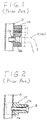
- Japanese Utility Model publication No. H3-128275 discloses a pair of header pipes 13 each having a union joint mechanism thereon for joining an inlet pipe 15 and an outlet pipe 16, respectively.
- a union joint mechanism includes union element 14 which is directly connected to header pipe 13 by brazing.
- inlet pipe 15 or outlet pipe 16 may be fixedly and hermetically joined with union element 14 for the purpose of freely selecting the position of inlet pipe 15 or outlet pipe 16 and increasing the strength of a union joint mechanism.
- union element 14 includes a fluid passage 14a integrally formed therein.
- One end of fluid passage 14a protrudes into the interior of header pipe 13. That end of fluid passage 14a is connected to hole 13a of header pipe 13 by brazing.
- Union element 14 may be made of a high hardness aluminum alloy, such as A7000 series aluminum alloys, which provides a strong body although such material is generally difficult to braze properly.
- union element 17 comprises an opening 17a formed therein.
- a sleeve member 18 may be inserted into opening 17a so that sleeve member 18 protrudes into the interior of header pipe 17. Fluid may flow through the inner surface of sleeve member 18
- Sleeve member 18 may be made of a material which is easily brazed in character. Thereby, sleeve member 18, which functions as a fluid path, may be securely connected to header pipe 13 by brazing.
- a flux material must be coated on the areas at which sleeve member 18 is connected to hole 13a of header pipe 13 and union element 17 is connected to the peripheral surface of header pipe 13 before brazing.
- This coating work is difficult because the areas to be coated are hidden by union element 17 when union element 17 is set on header pipe 13. Without the coating, however, the areas are difficult to braze and as a result, the heat exchanger may leak heat exchanger fluid at the brazing area and may have weak connections between header pipe 13 and union element 17.
- excess flux is coated on the connection areas to attempt to prevent leakage of the fluid and weakness of the connection, the flux flows into the interior of fluid passage 17a or sleeve member 18. Consequently, the heat exchanger does not seal properly when the heat exchanger is heated up in a furnace for brazing.
- the connecting area may not receive a sufficient amount of the brazing material for proper brazing because the brazing material may be absorbed in the gap created between sleeve member 18 and union element 17 or between union element 17 and the outer peripheral of header pipe 13.
- the leakage of the brazing material in the connecting area may result in leakage of the fluid and a deterioration of pressure strength and may not insure the strength of union element 17.
- the present invention comprises a heat exchanger for conducting a fluid.
- the heat exchanger comprises a plurality of heat transfer tubes having opposite first and second ends respectively.
- a plurality of fins are sandwiched by the heat transfer tubes.
- First and second header pipes are fixedly and hermetically connected to one of the opposite ends of each of the heat transfer tubes.
- a pair of union joint devices are disposed in the first and second header pipes respectively for linking the heat exchanger to an external element of a fluid circuit.
- Each of the union joint devices includes a union member therein, a fluid passage disposed in the union member, and a brazed area wherein one end of the fluid passage is brazed to a hole formed on the header pipe.
- a space is created around the brazed area for enabling a person to examine the condition of brazing and insuring a flux therein.
- Fig. 1 is an enlarged partial cross sections view of a union joint mechanism of a heat exchanger according to an embodiment of the prior art.
- Fig. 2 is an enlarged partial cross sectional view of a union joint mechanism of a heat exchanger according to another embodiment of the prior art.
- Fig. 3 is an elevational view of a heat exchanger according to an embodiment of the present invention.
- Fig. 4 is a top view of the heat exchanger shown in Fig. 3.
- Fig. 5 is an enlarged fragmentary sectional view taken along line 5-5 of Fig. 3.
- Fig. 6 is an overhead view of a union joint member according to an embodiment of the present invention.
- Fig. 7 is a side view of the union joint member shown in Fig. 6.
- Fig. 8 is schematic view of an external pipe joint member connected to a union joint mechanism according to another embodiment of the present invention.
- Fig. 9 is a schematic view of a union joint mechanism according to another embodiment of the present invention.
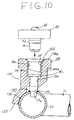
- Fig. 10 is an enlarged fragmentary sectional view taken along line 5-5 of Fig. 3 according to another embodiment of the present invention.
- Fig. 11 is an overhead view of union joint member according to another embodiment of the present invention.
- Fig. 12 is a side view of the union joint member shown in Fig. 11.
- a heat exchanger 20 includes a plurality of adjacent, essentially flat tubes 21 having an oval cross section and open ends which allow refrigerant fluid to flow therethrough.
- a plurality of corrugated fin units 22 may be disposed between adjacent tubes 21.
- Circular header pipes 23 and 24 may be disposed substantially perpendicularly to flat tubes 21a and may have, for example, a clad construction.
- Flat tubes 21 are fixedly connected to header pipes 23 and 24 and disposed in slots 27 such that the open end of flat tubes 21 communicate with the hollow interior of header pipes 23 and 24.
- Header pipe 23 may have a closed top end and a bottom end.
- Inlet union joint mechanism 32 may be fixedly and hermetically connected to header pipe 23. Inlet union joint mechanism 32 may also be linked to the outlet of a compressor (not shown).
- Partition wall 23a may be fixedly disposed within header pipe 23 at a location about midway along its length and may divide header pipe 23 into an upper cavity 231 and a lower cavity 232, which is isolated from upper cavity 231.
- Second header pipe 24 may also have a closed top end and a bottom end.
- Outlet union joint mechanism 33 may be fixedly and hermetically connected to header pipe 23. Outlet union joint mechanism 33 may be linked to the inlet of a receiver (not shown).
- Partition wall 24a may be fixedly disposed within second header pipe 24 at a location approximately one third of the way along the length of second header pipe 24 and may divide second header pipe 24 into an upper cavity 241 and a lower cavity 242, which is isolated from upper cavity 241.
- the location of partition wall 24a may be lower than the location of partition wall 23a.
- compressed refrigeration gas from a compressor flows into upper cavity 213 of first header pipe 23 through inlet union joint mechanism 32 and is distributed such that a portion of the gas flows through each of flat tubes 21 which is disposed above partition wall 23a and into an upper portion of upper cavity 241.
- the refrigerant in the upper portion of upper cavity 241 flows downward into the lower portion of upper cavity 241 and is distributed such that a portion flows through each of the plurality of flat tubes 21 disposed below partition wall 23a and partition wall 24a, and into an upper portion of lower cavity 232 of first header pipe 23.
- the refrigerant in an upper portion of lower cavity 232 flows downwardly into a lower portion of lower cavity 232 and is again distributed such that a portion flows through each of the plurality of flat tubes 21 disposed below partition wall 24a and into lower cavity 242 of second header pipe 24.
- heat from the refrigerant gas is exchanged with the atmospheric air flowing through corrugated fin unit 22 in the direction of arrow W as shown in Fig. 4. Since the refrigerant gas radiates heat to the outside air, it condenses to a liquid refrigerant in lower cavity 242 and flows from lower cavity 242 out through outlet union joint mechanism 33 and into the receiver and the further elements of the circuit as discussed above.
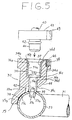
- union joint mechanism 32 includes a union element 34 and a sleeve member 37 inserted into an opening 36 integrally formed in union element 34.
- Union element 34 may comprise a rectangular-shaped body 34a, an opening 36 penetrating from a first end surface 34b to a second end surface 34c of union element 34, and an arm 35 extending from second end surface 34c.
- Arm 35 may comprise a wall portion 35a, an arc portion 35b extending from wall portion 35a, and an inner surface 35c of arm 35 formed on arc portion 35b.
- Inner surface 35c may be desired to closely contact the peripheral surface of header pipe 23.
- Opening 36 may comprise a first cylindrical hole 36a, a second cylindrical hole 36b, a shoulder portion 36c joining first cylindrical hole 35a to second cylindrical hole 36b, and a beveling surface 36d joining first end surface 34b to first cylindrical hole 36a.
- the inner diameter of first cylindrical hole 36a may be larger than that of secured cylindrical hole 36b.
- Sleeve member 37 may comprise a first cylindrical portion 37a, a second cylindrical portion 37b, a third cylindrical portion 37c, a first shoulder portion 37d joining first cylindrical portion 37a to second cylindrical portion 37b, a second shoulder portion 37e joining second cylindrical portion 37b to third cylindrical portion 37c, and a flange portion 37f extending from one end of first cylindrical portion 37a.
- the outer diameter of first cylindrical portion 37a may be larger than that of second cylindrical portion 37b.
- the outer diameter of second cylindrical portion 37b may be larger than that of third cylindrical portion 37c.
- sleeve member 37 may be forcibly inserted into opening 36 of union element 34 such that third cylindrical portion 37c and a partial portion of second cylindrical portion 37b substantially protrude from second end surface 34c of union element 34.
- Union element 34 may be made of a metal, for example, such as an aluminum alloy series 7000, which is difficult to braze but is very hard.
- Sleeve member 37 may be made of a metal, for example, such as A3000 series aluminum alloy which is easily brazed.
- union element 34 may comprise a thread hole 46 straightly penetrating from first end surface 34b toward the inside of body 34a.
- Union element 34 may further comprise a cutaway portion 49 formed on a first side surface 34d. Cutaway portion 49 may completely join first side surface 34d to a second end surface 34c.
- union element 34 may be securely connected to header pipe 23 at first joint area 38 such that inner surface 37c of arm 35 may be brazed to the peripheral surface of header pipe 23.
- Sleeve member 37 may also be fixedly and hermetically connected to header pipe 23 at second joint area 39 such that second shoulder portion 37e may be brazed to the circumference of hole 23b of header pipe 23.
- the external joint mechanism may comprise a joint block 43, a first pipe member 40 connected to one end surface therein, and a second pipe member 42, which is provided with an "O"-ring 42 thereon, connected to the other end surface therein.
- Joint block 43 includes hole 45 through which bolt 44 may be passed. After second pipe member 42 is inserted into opening 36 of union element 34, the external joint mechanism may be secured to union joint mechanism 32 such that bolt 44 penetrates hole 45 and is bound in thread hole 46.
- wall portion 35a and second end surface 34c collectively form space 47 around the outer peripheral surface of second cylindrical portion 37b of sleeve member 37. Therefore, space 47 functions to maintain flux therein without permitting the flux to deviate into other gaps. Further, second joint area 39 may be securely brazed since space 47 also functions to insure a desirable amount of brazing material therein for brazing. Second joint area 39 thus provides superior sealing and strength in construction.
- an operator may be able to confirm whether the flux has properly coated second joint area 39 by observing the second joint area 39 through space 47. If it is not sufficiently coated, the flux may be supplemented at second joint area 39.
- the operator may confirm whether second joint area 39 is properly brazed by observing second joint area 39 from three direction as indicated by the arrows shown in Fig. 9. Therefore, if union element 34 includes either inclined portion 49 or space 47, the operator may confirm the coating condition of the flux and the resulting brazing condition as well.
- the improvement may decrease the leakage of the fluid from header pipe 23 (24) and may facilitate control of the production process in inspecting leakage of the fluid.
- FIG. 10 another embodiment of the present invention is depicted. Elements similar to those of the other embodiments are designated with the same references numerals.
- a union joint mechanism 132 may comprise a union element 134 and a sleeve member 37 inserted into an opening 36 formed in union element 134.
- Union element 134 may comprise a rectangular shape body 134a, an opening 36 penetrating from a first end surface 134b to a second end surface 134c of union element 134, and an arm 135 extending from second end surface 134c.
- Union element 134 may comprise a thread hole 146 penetrating straight from first end surface 134b toward the inside of body 134a.
- Union element 134 may also comprise a notch portion 147 formed in body 134a so as to surround second cylindrical hole 36b and extend along the peripheral surface of sleeve member 37.
- Union element 134 may further comprise a cutaway portion 149 formed on one side surface 134d. Cutaway portion 149 inclines toward second end surface 134c and completely joins side surface 134d to second end surface 134c. Union element 134 may be securely connected to header pipe 23 at first joint area 138 such that arm 135 is brazed to the peripheral surface of header pipe 23. Sleeve member 37 may also be fixedly and hermetically connected to header pipe 23 at second joint area 139 such that second shoulder portion 37e is brazed to the circumference of hole 23b of header pipe 23. This structure also provides the advantages of the embodiments of Figs. 3-9 as discussed above.
Landscapes
- Engineering & Computer Science (AREA)
- Physics & Mathematics (AREA)
- Thermal Sciences (AREA)
- Mechanical Engineering (AREA)
- General Engineering & Computer Science (AREA)
- Details Of Heat-Exchange And Heat-Transfer (AREA)
- Heat-Exchange Devices With Radiators And Conduit Assemblies (AREA)
- Flanged Joints, Insulating Joints, And Other Joints (AREA)
Applications Claiming Priority (2)
| Application Number | Priority Date | Filing Date | Title |
|---|---|---|---|
| JP168303/95 | 1995-06-09 | ||
| JP16830395A JP3406424B2 (ja) | 1995-06-09 | 1995-06-09 | 熱交換器の配管接続部構造 |
Publications (2)
| Publication Number | Publication Date |
|---|---|
| EP0747650A1 true EP0747650A1 (de) | 1996-12-11 |
| EP0747650B1 EP0747650B1 (de) | 1998-04-08 |
Family
ID=15865526
Family Applications (1)
| Application Number | Title | Priority Date | Filing Date |
|---|---|---|---|
| EP96108950A Expired - Lifetime EP0747650B1 (de) | 1995-06-09 | 1996-06-04 | Einlass- und Auslassverbindungsstück für einen Wärmetauscher |
Country Status (7)
| Country | Link |
|---|---|
| US (1) | US5711370A (de) |
| EP (1) | EP0747650B1 (de) |
| JP (1) | JP3406424B2 (de) |
| CN (1) | CN1106566C (de) |
| AR (1) | AR010197A1 (de) |
| DE (1) | DE69600219T2 (de) |
| MY (1) | MY121958A (de) |
Cited By (7)
| Publication number | Priority date | Publication date | Assignee | Title |
|---|---|---|---|---|
| WO1999057501A1 (en) * | 1998-05-05 | 1999-11-11 | Norsk Hydro Asa | Heat exchanger manifold block with improved brazeability |
| WO2000029800A1 (en) * | 1998-11-17 | 2000-05-25 | Norsk Hydro Asa | Heat exchanger mounting bracket with integrated inlet/outlet block and locating sleeve |
| EP1426723A1 (de) * | 2002-11-29 | 2004-06-09 | Calsonic Kansei Corporation | Wärmeaustauscher |
| EP1914498A1 (de) * | 2006-10-18 | 2008-04-23 | Behr France Hambach S.A.R.L. | Flansch, insbesondere für einen Wärmetauscher |
| WO2010105689A3 (de) * | 2009-03-20 | 2011-04-21 | A-Heat Allied Heat Exchange Technology Ag | Verbindungsanschluss, wärmetauscherblock, sowie ein verfahren zur herstellung eines wärmetauscherblocks |
| WO2014124847A1 (de) * | 2013-02-16 | 2014-08-21 | Volkswagen Aktiengesellschaft | Kühleinrichtung für ein kraftfahrzeug |
| LU500556B1 (en) * | 2021-08-19 | 2023-02-20 | Estra Automotive Systems Luxembourg S A R L | Condenser with receiver dryer |
Families Citing this family (22)
| Publication number | Priority date | Publication date | Assignee | Title |
|---|---|---|---|---|
| US5911274A (en) * | 1995-12-06 | 1999-06-15 | Calsonic Corporation | Joint portion of heat exchanger |
| EP0953815B1 (de) * | 1998-04-30 | 2003-08-06 | Showa Denko K.K. | Anschlussvorrichtung für Wärmetauscher |
| US6908117B1 (en) | 2000-10-06 | 2005-06-21 | Hutchinson Fts, Inc. | Block-conduit connection alignment device |
| JP3805628B2 (ja) * | 2001-01-29 | 2006-08-02 | 株式会社ヴァレオサーマルシステムズ | 熱交換器 |
| US7260893B2 (en) * | 2004-01-09 | 2007-08-28 | Delphi Technologies, Inc. | Method of attaching a transmission oil cooler to an aluminum tank |
| US7077194B2 (en) * | 2004-02-26 | 2006-07-18 | Denso International America, Inc. | Brazed condenser jumper tube |
| JP4707462B2 (ja) * | 2005-05-31 | 2011-06-22 | カルソニックカンセイ株式会社 | 熱交換器の配管接続構造 |
| US7967060B2 (en) * | 2005-08-18 | 2011-06-28 | Parker-Hannifin Corporation | Evaporating heat exchanger |
| US7658224B2 (en) * | 2005-09-19 | 2010-02-09 | Dana Canada Corporation | Flanged connection for heat exchanger |
| JP4934379B2 (ja) * | 2006-09-19 | 2012-05-16 | 昭和電工株式会社 | 熱交換器 |
| DE102009039569A1 (de) | 2009-09-01 | 2011-03-03 | Behr Gmbh & Co. Kg | Gaskühler für einen Verbrennungsmotor |
| DE102010029777A1 (de) * | 2010-06-08 | 2011-12-08 | Behr Gmbh & Co. Kg | Anschlussflansch für einen Wärmetauscher |
| DE102013005796A1 (de) * | 2013-04-04 | 2014-10-09 | Modine Manufacturing Co. | Stutzenanbindung für Wärmetauscher |
| JP6102551B2 (ja) * | 2013-06-18 | 2017-03-29 | 株式会社デンソー | 熱交換器の製造方法 |
| US9810453B2 (en) * | 2015-01-05 | 2017-11-07 | Articmaster Inc. | Device for improving the efficiency of a heat exchange system |
| US10005353B2 (en) * | 2014-10-29 | 2018-06-26 | Denso International America, Inc. | Mounting structure for in-tank oil cooler and radiator |
| CN106239016A (zh) * | 2016-10-21 | 2016-12-21 | 山东电力设备有限公司 | 一种特高压变压器联管焊接定位工装 |
| US10106028B1 (en) * | 2017-05-31 | 2018-10-23 | GM Global Technology Operations LLC | Internal transmission oil cooler mounting strategy |
| US10344863B2 (en) * | 2017-08-30 | 2019-07-09 | Hanon Systems | Metal seal fitting for in-tank transmission oil cooler |
| EP3901506A1 (de) * | 2020-04-24 | 2021-10-27 | Carrier Corporation | Rohrverbindungsanordnung für einen wärmetauscher |
| US12135177B2 (en) | 2020-08-14 | 2024-11-05 | Viking Vessel Holdings, Llc | Tube transition |
| US12130101B2 (en) * | 2020-08-14 | 2024-10-29 | Viking Vessel Holdings, Llc | Tube transition |
Citations (1)
| Publication number | Priority date | Publication date | Assignee | Title |
|---|---|---|---|---|
| EP0516413A1 (de) * | 1991-05-31 | 1992-12-02 | Showa Aluminum Corporation | Wärmetauscher |
Family Cites Families (17)
| Publication number | Priority date | Publication date | Assignee | Title |
|---|---|---|---|---|
| JPH0711335Y2 (ja) * | 1989-01-30 | 1995-03-15 | サンデン株式会社 | 熱交換器 |
| JPH0321665U (de) * | 1989-07-14 | 1991-03-05 | ||
| JPH087247Y2 (ja) * | 1989-10-06 | 1996-03-04 | サンデン株式会社 | 熱交換器 |
| US5228727A (en) * | 1989-12-28 | 1993-07-20 | Showa Aluminum Corporation | Tubular body having pipe joint member attached thereto and method of producing same |
| JP2547219Y2 (ja) * | 1990-03-28 | 1997-09-10 | 昭和アルミニウム株式会社 | 熱交換器 |
| US5419042A (en) * | 1990-07-24 | 1995-05-30 | Sanden Corporation | Method for temporarily assembling a heat exchanger |
| JPH04129686U (ja) * | 1991-05-10 | 1992-11-27 | サンデン株式会社 | 熱交換器 |
| US5163716A (en) * | 1991-10-25 | 1992-11-17 | General Motors Corporation | Condenser connector assembly for connecting refrigerant line |
| JPH05180592A (ja) * | 1991-12-27 | 1993-07-23 | Showa Alum Corp | 熱交換器 |
| JP2980445B2 (ja) * | 1992-01-23 | 1999-11-22 | 昭和アルミニウム株式会社 | 熱交換器 |
| US5186248A (en) * | 1992-03-23 | 1993-02-16 | General Motors Corporation | Extruded tank condenser with integral manifold |
| US5186246A (en) * | 1992-06-01 | 1993-02-16 | General Motors Corporation | Extruded coolant/refrigerant tank with separate headers |
| JPH0631333A (ja) * | 1992-07-22 | 1994-02-08 | Hitachi Metals Ltd | 溶接管製造用冷却装置付スクイズロール |
| JP3159805B2 (ja) * | 1992-10-12 | 2001-04-23 | 昭和アルミニウム株式会社 | 熱交換器 |
| JP3212730B2 (ja) * | 1993-01-20 | 2001-09-25 | 昭和電工株式会社 | 熱交換器 |
| US5346003A (en) * | 1993-10-12 | 1994-09-13 | General Motors Corporation | Face plumbed condenser for automotive air conditioner |
| JP7117354B2 (ja) | 2020-09-14 | 2022-08-12 | 株式会社Kokusai Electric | 半導体装置の製造方法、基板処理装置、およびプログラム |
-
1995
- 1995-06-09 JP JP16830395A patent/JP3406424B2/ja not_active Expired - Fee Related
-
1996
- 1996-06-04 EP EP96108950A patent/EP0747650B1/de not_active Expired - Lifetime
- 1996-06-04 DE DE69600219T patent/DE69600219T2/de not_active Expired - Lifetime
- 1996-06-06 AR ARP960102985A patent/AR010197A1/es unknown
- 1996-06-06 US US08/659,514 patent/US5711370A/en not_active Expired - Lifetime
- 1996-06-06 MY MYPI96002218A patent/MY121958A/en unknown
- 1996-06-09 CN CN96110746A patent/CN1106566C/zh not_active Expired - Fee Related
Patent Citations (1)
| Publication number | Priority date | Publication date | Assignee | Title |
|---|---|---|---|---|
| EP0516413A1 (de) * | 1991-05-31 | 1992-12-02 | Showa Aluminum Corporation | Wärmetauscher |
Cited By (10)
| Publication number | Priority date | Publication date | Assignee | Title |
|---|---|---|---|---|
| WO1999057501A1 (en) * | 1998-05-05 | 1999-11-11 | Norsk Hydro Asa | Heat exchanger manifold block with improved brazeability |
| US6154960A (en) * | 1998-05-05 | 2000-12-05 | Norsk Hydro A.S. | Enhancements to a heat exchanger manifold block for improving the brazeability thereof |
| WO2000029800A1 (en) * | 1998-11-17 | 2000-05-25 | Norsk Hydro Asa | Heat exchanger mounting bracket with integrated inlet/outlet block and locating sleeve |
| EP1426723A1 (de) * | 2002-11-29 | 2004-06-09 | Calsonic Kansei Corporation | Wärmeaustauscher |
| US7011149B2 (en) | 2002-11-29 | 2006-03-14 | Calsonic Kansei Corporation | Heat exchanger |
| EP1914498A1 (de) * | 2006-10-18 | 2008-04-23 | Behr France Hambach S.A.R.L. | Flansch, insbesondere für einen Wärmetauscher |
| WO2010105689A3 (de) * | 2009-03-20 | 2011-04-21 | A-Heat Allied Heat Exchange Technology Ag | Verbindungsanschluss, wärmetauscherblock, sowie ein verfahren zur herstellung eines wärmetauscherblocks |
| WO2014124847A1 (de) * | 2013-02-16 | 2014-08-21 | Volkswagen Aktiengesellschaft | Kühleinrichtung für ein kraftfahrzeug |
| KR20150104163A (ko) * | 2013-02-16 | 2015-09-14 | 폭스바겐 악티엔 게젤샤프트 | 차량용 냉각 장치 |
| LU500556B1 (en) * | 2021-08-19 | 2023-02-20 | Estra Automotive Systems Luxembourg S A R L | Condenser with receiver dryer |
Also Published As
| Publication number | Publication date |
|---|---|
| CN1106566C (zh) | 2003-04-23 |
| CN1157908A (zh) | 1997-08-27 |
| US5711370A (en) | 1998-01-27 |
| DE69600219D1 (de) | 1998-05-14 |
| AR010197A1 (es) | 2000-06-07 |
| JP3406424B2 (ja) | 2003-05-12 |
| MY121958A (en) | 2006-03-31 |
| JPH08338580A (ja) | 1996-12-24 |
| EP0747650B1 (de) | 1998-04-08 |
| DE69600219T2 (de) | 1998-10-29 |
Similar Documents
| Publication | Publication Date | Title |
|---|---|---|
| US5711370A (en) | Inlet and outlet union mechanisms of a heat exchanger | |
| US6216776B1 (en) | Heat exchanger | |
| US5918667A (en) | Heat exchanger | |
| US5826648A (en) | Laminated type heat exchanger | |
| US5242015A (en) | Heat exchanger | |
| US20030155109A1 (en) | Heat exchanger | |
| US5082051A (en) | Heat exchanger having a corrosion prevention means | |
| JP2004347210A (ja) | 熱交換器の配管接続構造 | |
| CN114174727B (zh) | 冷冻装置及所述冷冻装置的制冷剂配管 | |
| US5941304A (en) | Connector for heat exchanger | |
| US5094293A (en) | Heat exchanger | |
| US5097900A (en) | Condenser having partitions for changing the refrigerant flow direction | |
| KR100452006B1 (ko) | 열교환기의이음부 | |
| US4957158A (en) | Heat exchanger | |
| US6443224B2 (en) | Piping structure for heat exchanger, piping joint block for heat exchanger and heat exchanger with said joint block | |
| US5179845A (en) | Heat exchanger | |
| CA2018962C (en) | Capillary tube assembly and method of manufacture | |
| JPH05157486A (ja) | 熱交換器 | |
| JP2010025460A (ja) | 二重管式熱交換器用継手 | |
| JPH0631335Y2 (ja) | 熱交換器の配管接続構造 | |
| JPH02247498A (ja) | 熱交換器 | |
| JPH07174095A (ja) | 密閉型圧縮機 | |
| JP2000257992A (ja) | 受液器の連結構造 | |
| JPH04161798A (ja) | 2重管式熱交換器 | |
| JPH07103683A (ja) | 熱交換器 |
Legal Events
| Date | Code | Title | Description |
|---|---|---|---|
| PUAI | Public reference made under article 153(3) epc to a published international application that has entered the european phase |
Free format text: ORIGINAL CODE: 0009012 |
|
| AK | Designated contracting states |
Kind code of ref document: A1 Designated state(s): DE FR GB IT SE |
|
| 17P | Request for examination filed |
Effective date: 19961210 |
|
| 17Q | First examination report despatched |
Effective date: 19970304 |
|
| GRAG | Despatch of communication of intention to grant |
Free format text: ORIGINAL CODE: EPIDOS AGRA |
|
| GRAG | Despatch of communication of intention to grant |
Free format text: ORIGINAL CODE: EPIDOS AGRA |
|
| GRAG | Despatch of communication of intention to grant |
Free format text: ORIGINAL CODE: EPIDOS AGRA |
|
| GRAH | Despatch of communication of intention to grant a patent |
Free format text: ORIGINAL CODE: EPIDOS IGRA |
|
| GRAH | Despatch of communication of intention to grant a patent |
Free format text: ORIGINAL CODE: EPIDOS IGRA |
|
| GRAA | (expected) grant |
Free format text: ORIGINAL CODE: 0009210 |
|
| AK | Designated contracting states |
Kind code of ref document: B1 Designated state(s): DE FR GB IT SE |
|
| ITF | It: translation for a ep patent filed | ||
| REF | Corresponds to: |
Ref document number: 69600219 Country of ref document: DE Date of ref document: 19980514 |
|
| ET | Fr: translation filed | ||
| PLBE | No opposition filed within time limit |
Free format text: ORIGINAL CODE: 0009261 |
|
| STAA | Information on the status of an ep patent application or granted ep patent |
Free format text: STATUS: NO OPPOSITION FILED WITHIN TIME LIMIT |
|
| 26N | No opposition filed | ||
| REG | Reference to a national code |
Ref country code: GB Ref legal event code: IF02 |
|
| PGFP | Annual fee paid to national office [announced via postgrant information from national office to epo] |
Ref country code: SE Payment date: 20020611 Year of fee payment: 7 |
|
| PG25 | Lapsed in a contracting state [announced via postgrant information from national office to epo] |
Ref country code: SE Free format text: LAPSE BECAUSE OF NON-PAYMENT OF DUE FEES Effective date: 20030605 |
|
| EUG | Se: european patent has lapsed | ||
| PGFP | Annual fee paid to national office [announced via postgrant information from national office to epo] |
Ref country code: FR Payment date: 20110621 Year of fee payment: 16 |
|
| PGFP | Annual fee paid to national office [announced via postgrant information from national office to epo] |
Ref country code: GB Payment date: 20110601 Year of fee payment: 16 |
|
| PGFP | Annual fee paid to national office [announced via postgrant information from national office to epo] |
Ref country code: IT Payment date: 20110616 Year of fee payment: 16 |
|
| GBPC | Gb: european patent ceased through non-payment of renewal fee |
Effective date: 20120604 |
|
| PG25 | Lapsed in a contracting state [announced via postgrant information from national office to epo] |
Ref country code: IT Free format text: LAPSE BECAUSE OF NON-PAYMENT OF DUE FEES Effective date: 20120604 |
|
| REG | Reference to a national code |
Ref country code: FR Ref legal event code: ST Effective date: 20130228 |
|
| PG25 | Lapsed in a contracting state [announced via postgrant information from national office to epo] |
Ref country code: FR Free format text: LAPSE BECAUSE OF NON-PAYMENT OF DUE FEES Effective date: 20120702 Ref country code: GB Free format text: LAPSE BECAUSE OF NON-PAYMENT OF DUE FEES Effective date: 20120604 |
|
| PGFP | Annual fee paid to national office [announced via postgrant information from national office to epo] |
Ref country code: DE Payment date: 20130628 Year of fee payment: 18 |
|
| REG | Reference to a national code |
Ref country code: DE Ref legal event code: R119 Ref document number: 69600219 Country of ref document: DE |
|
| REG | Reference to a national code |
Ref country code: DE Ref legal event code: R119 Ref document number: 69600219 Country of ref document: DE Effective date: 20150101 |
|
| PG25 | Lapsed in a contracting state [announced via postgrant information from national office to epo] |
Ref country code: DE Free format text: LAPSE BECAUSE OF NON-PAYMENT OF DUE FEES Effective date: 20150101 |