EP0747863A2 - Kartenanzeigegerät - Google Patents
Kartenanzeigegerät Download PDFInfo
- Publication number
- EP0747863A2 EP0747863A2 EP96304297A EP96304297A EP0747863A2 EP 0747863 A2 EP0747863 A2 EP 0747863A2 EP 96304297 A EP96304297 A EP 96304297A EP 96304297 A EP96304297 A EP 96304297A EP 0747863 A2 EP0747863 A2 EP 0747863A2
- Authority
- EP
- European Patent Office
- Prior art keywords
- bird
- eye view
- map
- map data
- vehicle
- Prior art date
- Legal status (The legal status is an assumption and is not a legal conclusion. Google has not performed a legal analysis and makes no representation as to the accuracy of the status listed.)
- Granted
Links
Images


Classifications
-
- G—PHYSICS
- G08—SIGNALLING
- G08G—TRAFFIC CONTROL SYSTEMS
- G08G1/00—Traffic control systems for road vehicles
- G08G1/09—Arrangements for giving variable traffic instructions
- G08G1/0962—Arrangements for giving variable traffic instructions having an indicator mounted inside the vehicle, e.g. giving voice messages
- G08G1/0968—Systems involving transmission of navigation instructions to the vehicle
- G08G1/0969—Systems involving transmission of navigation instructions to the vehicle having a display in the form of a map
-
- G—PHYSICS
- G06—COMPUTING OR CALCULATING; COUNTING
- G06T—IMAGE DATA PROCESSING OR GENERATION, IN GENERAL
- G06T17/00—Three-dimensional [3D] modelling for computer graphics
- G06T17/05—Geographic models
-
- G—PHYSICS
- G01—MEASURING; TESTING
- G01C—MEASURING DISTANCES, LEVELS OR BEARINGS; SURVEYING; NAVIGATION; GYROSCOPIC INSTRUMENTS; PHOTOGRAMMETRY OR VIDEOGRAMMETRY
- G01C21/00—Navigation; Navigational instruments not provided for in groups G01C1/00 - G01C19/00
- G01C21/26—Navigation; Navigational instruments not provided for in groups G01C1/00 - G01C19/00 specially adapted for navigation in a road network
- G01C21/34—Route searching; Route guidance
- G01C21/36—Input/output arrangements for on-board computers
- G01C21/3626—Details of the output of route guidance instructions
- G01C21/3635—Guidance using 3D or perspective road maps
-
- G—PHYSICS
- G06—COMPUTING OR CALCULATING; COUNTING
- G06T—IMAGE DATA PROCESSING OR GENERATION, IN GENERAL
- G06T15/00—Three-dimensional [3D] image rendering
- G06T15/10—Geometric effects
- G06T15/20—Perspective computation
Definitions
- the present invention relates to a map display apparatus that is capable of displaying road information or the like as a bird's-eye view map in the bird's eye view format obtained by looking down diagonally at a map in a specific direction from above.
- map display apparatuses for vehicles in the prior art that display a road map on a display device in the so called bird's-eye view display format, whereby a road map in the vicinity of the current position of the vehicle is displayed magnified compared to portions of the map in the distance (refer to U.S.P. No. 5,161,886, for instance).
- the apparatus disclosed in the above-mentioned application sets a viewpoint to the rear of the current position of the vehicle and displays the road state on the ground from this viewpoint looking down in the advancing direction of the vehicle on a screen of a display device.
- map information in the vicinity of the current vehicle position can be displayed enlarged, and in addition, since a wide range of area from the current position to distant positions can be displayed, it is easy to visually read route connections on the road map.
- Another advantage is achieved when the display direction, i.e., the direction in which the road map is looked down upon, is set to match the advancing direction of the vehicle, in that intersections and the like on the path of the vehicle's advance can be observed in detail, making the road map very easy to see when the path of advance is a linear path.
- An object of the present invention is to provide a map display apparatus with which, when a map is displayed in the bird's-eye view format, the display direction of the bird's-eye view map can be changed freely to ensure that the state in the vicinity of the current position can be accurately understood.
- a map display apparatus comprises: a road map storage device that stores road map data related to a road map; a vehicle position detection device that detects a current position of a vehicle; a monitor that displays a road map in a bird's-eye view format based upon bird's-eye view map data that are input; a bird's-eye view map data creation circuit that creates the bird's-eye view map data in the bird's-eye view format obtained by looking down at the road map diagonally in a predefined specific direction from a viewpoint above a vicinity of the current position of the vehicle on the road map, based upon the road map data read from the road map storage device and the current position of the vehicle detected by the vehicle position detection device; a direction change operating member that is operated in order to change the specific direction that is used when the bird's-eye view map data is created; and a control circuit that controls the bird's-eye view map data creation circuit so as to create the bird's-eye view map data in the specific
- Another map display apparatus comprises: a data conversion circuit that converts a plane map data to a bird's-eye view map data in a specific bird's-eye viewing direction in order to display a map in a bird's-eye view format; and an operating member that is operated to change the specific bird's-eye viewing direction.
- FIG. 1 is a block diagram of an embodiment of the map display apparatus according to the present invention.
- FIG. 2 is a flowchart illustrating the main processing performed by the control circuit.
- FIG. 3 is a flowchart illustrating the bird's-eye view map display processing performed by the control circuit.
- FIG. 4 is an illustration of the method employed for conversion to bird's-eye view map data.
- FIG. 5 is an enlargement of the rectangular area abcd shown in FIG. 4.
- FIG. 6 is a flowchart illustrating the interruption processing performed when the joy-stick has been operated.
- FIG. 7A is an illustration of change in the display direction of the bird's-eye view map.
- FIG. 7B is another illustration of change in the display direction of the bird's-eye view map.
- FIG. 8A is an example of bird's-eye view map display.
- FIG. 8B is another example of bird's-eye view map display.
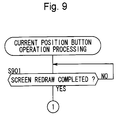
- FIG. 9 is a flowchart illustrating the processing performed when the current position button has been operated.
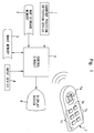
- FIG. 1 is a block diagram of an embodiment of the map display apparatus for vehicles according to the present invention.
- reference number 1 indicates a current position detection device that detects the current position of a vehicle and is constituted with, for instance, a bearing sensor that detects the advancing bearing of the vehicle, a vehicle speed sensor that detects the speed of the vehicle, a GPS sensor that detects GPS signals sent from a GPS (Global Positioning System) satellite and the like.
- Reference number 2 indicates a map storage memory that stores road map data and is used to temporarily store map data obtained by reading out road map data in, for instance, a CD ROM, with a read device.
- the road map data stored in the map storage memory 2 are mainly constituted with road data, name data, background data and the like. Furthermore, road map data at a plurality of map scales are stored in the map storage memory 2.
- Reference number 3 indicates a control circuit, constituted with a microprocessor and its peripheral circuits that controls the entire apparatus.
- Reference number 4 indicates an input device, constituted with various types of push-button switches provided on the panel surface to the left and right of the display device 6, which is to be detailed later.
- Reference number 5 indicates an image memory for storing image data and reference number 6 indicates the display device, which displays various types of information based upon the image data stored in the image memory 5.
- Reference number 7 indicates a remote control device provided with a joy-stick 7a that may be operated in 8 directions, i.e., up, down, left, right, diagonally upward and to the right, diagonally downward and to the right, diagonally upward and to the left and diagonally downward and to the left, a current position button 7b for issuing a command to display the vehicle current position and a button group 7c for issuing various other commands. While it is desirable that the remote control device 7 employ the wireless remote control method, it may also employ the wired remote control method.
- a joy-stick similar to that of the remote control device may be mounted on the display panel surface.
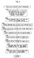
- FIG. 2 is a flowchart showing the main processing performed by the control circuit 3.
- the processing starts when the ignition key of the vehicle is operated to the ignition-on position.
- step S1 the current position and the advancing direction of the vehicle are detected with the current position detection device 1.
- the so-called GPS navigation method uses the GPS sensor to detect the current position
- a vehicle speed sensor and a bearing sensor are provided instead of a GPS sensor
- the so-called self contained navigation method determines the traveling locus of the vehicle to detect the current position.
- the current position may be detected by combining the GPS method and the self contained navigation method.
- the advancing direction of the vehicle is detected by using a bearing sensor or a geomagnetic sensor (not shown).
- step S2 in order to display a bird's-eye view map in the advancing direction of the vehicle, the display direction of the bird's-eye view map is determined based upon the advancing direction of the vehicle detected in step S1.
- step S3 a bird's-eye view map display processing is performed.
- the bird's-eye view map display processing is to be explained in detail later, in reference to FIG. 3.
- step S4 as in step S1, the current position and the advancing bearing of the vehicle are detected.
- step S5 a decision is made as to whether or not the vehicle has traveled at least a specific distance. The traveling distance can be calculated based on a signal from the vehicle speed sensor or the like. If an affirmative decision is made in step S5, the operation returns to step S2, whereas if a negative decision is made, the operation proceeds to step S6.
- step S6 a decision is made as to whether or not the advancing direction of the vehicle has changed. The decision making in regard to any change in the advancing direction of the vehicle can be performed based upon signals that are successively detected by the bearing sensor or the geomagnetic sensor. If an affirmative decision is made in step S6, the operation proceeds to step S7, in which the vehicle mark and the bearing marks are redrawn without updating the road map, and then the operation returns to step S4.
- the vehicle mark refers to a mark that indicates the current position and the advancing direction of the vehicle on the display screen and the bearing marks indicate the display direction of the bird's-eye view map and the advancing direction of the vehicle.
- the display direction of the bird's-eye view map is indicated with the alphabetical letters E, W, S and N indicating the bearings east, west, south and north and the advancing direction of the vehicle is indicated with filled triangles above and below the alphabetical letters E, W, S or N.
- the display position and the display direction of the vehicle mark are changed in correspondence to the current position and the advancing direction of the vehicle and the bearing marks are also changed in correspondence to the advancing direction of the vehicle.
- the bearing marks are to be described in detail later.
- step S6 If a negative decision is made in step S6, the operation proceeds to step S8, in which only the display position of the mark indicating the current position of the vehicle is changed in correspondence to the distance traveled by the vehicle, without changing its display direction, and then the operation returns to step S4.
- FIG. 3 is a flowchart showing details of the processing performed in step S3.
- step S301 based on the current position detected in step S1 and the display direction determined in step S2 of the main flowchart, road map data for the vicinity of the current position in the display direction that has been set are read from the map storage memory 2. For instance, road map data for an area of several tens of square kilometers including the current position are read.
- step S302 the data that are to be used for displaying a bird's-eye view map are selected from the road map data read in step S301.
- step S303 the road map data selected in step S302 are converted to bird's-eye view map data. The data conversion is to be detailed later.
- step S304 the bird's-eye view map data obtained through the conversion performed in step S303 are converted to the final map image data required for display on the display device 6.
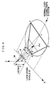
- FIG. 4 illustrates the conversion of road map data to bird's-eye view map data and shows an example in which a road map constitutes an X_Y plane, with a viewpoint M set on a Z axis, which runs at a right angle to the X_Y plane, with the look-down angle from the viewpoint M, i.e., the angle formed by a line connecting the viewpoint M and the vehicle current position PV relative to the X_Y plane, set at ⁇ .
- a rectangle abcd in the figure indicates the display range on the display device 6 as shown in an enlargement in FIG. 5 and the trapezoidal area ABCD in FIG. 4 indicates the road map range to be displayed on the display device 6.
- step S303 in order to display the entire road map data inside the trapezoidal area ABCD on the display device 6, the height Z of the viewpoint M, the look-down angle ⁇ from the viewpoint M and the aspect angle ⁇ from the viewpoint are first determined and then using these parameters, the bird's-eye view map data to be projected in the rectangular area abcd in FIG. 5 are created.
- the look-down angle ⁇ is set ensuring that the advancing direction of the vehicle extends in the vicinity of the central line connecting the middle points of the upper side and the lower side of the display screen of the display device 6.
- step S305 the character notations for the bearing marks to be displayed in the upper left area of the display screen are selected.
- the bearing marks indicate the display direction of the bird's-eye view map and the advancing direction of the vehicle and are displayed in the upper left area of the display screen as bearing information, which is constituted of a set of three character notations from among the eight character notations listed below. For instance, if the display direction is north, which matches the advancing direction of the vehicle, NW and NE are displayed to the left and right of N at the middle, as shown in FIG. 8A and, in combination with that, filled triangles indicating the advancing direction of the vehicle are displayed above and below the N.
- step S306 the image data required for displaying the bearing information, constituted of a set of three selected bearings, on the display screen, are created.
- step S307 the vehicle information image data required for displaying the vehicle mark on the display device 6 are created.
- step S308 the map image data, the bearing information image data and the vehicle information image data that were created in steps S304, S306 and S307 respectively are stored in the image memory 5.
- step S309 the screen of the display device 6 is drawn based upon the data stored in the image memory 5. With this, the bird's-eye view map, as shown in FIG. 8A, is displayed on the display device 6.
- FIG. 6 is a flowchart showing joy-stick operation processing.
- This program is started up when the control circuit 3 receives an interrupt signal generated by operation of the joy-stick 7a.
- step S601 the operation waits for the screen redraw to be completed. With this, even if the joy-stick 7a is operated during updating of the screen, the execution of this processing is held in standby until the screen is updated.
- step S602 the operation proceeds to step S602, in which a decision is made as to the direction in which the joy-stick 7a has been operated. In other words, if the joy-stick has been operated in a direction other than the right or left direction, processing is terminated, whereas if the joy-stick has been operated to the right or left, the operation proceeds to step S603.
- step S603 If it is decided that the joy-stick has been operated in the right direction in step S603, the operation proceeds to step S604, in which a new display direction is set toward the right by 10 degrees relative to the immediately preceding display direction and the bird's-eye view map display processing is executed in step S605. Then, if it is decided in step S606 that the joy-stick 7a has been operated in the right direction continuously for a specific length of time, the operation returns to step S604, whereas, if a negative decision is made in step S606, the processing is terminated and the operation returns.
- FIG. 7A illustrates the display direction for the bird's-eye view map when the joy-stick 7a has been operated in the right direction.
- the display direction D2 is a direction obtained by rotating the display direction D1 to the right by (10 x n) degrees around the vehicle current position PV and the display range R2 is the area enclosed by the broken lines. Consequently, if the display direction D1 is the vehicle advancing direction, more of the road state on the right hand side relative to the advancing direction is displayed within the screen.
- step S603 If it is decided in step S603 that the joy-stick has not been operated in the right direction, the operation proceeds to step S610 and if it is decided in step S610 that the joy-stick has been operated in the left direction, the operation proceeds to step S611, in which a new display direction is set toward the left by 10 degrees relative to the immediately preceding display direction before the bird's-eye view map display processing is executed in step S612. Then, if it is decided in step S613 that the joy-stick has been operated in the left direction continuously for a specific length of time, the operation returns to step S611, whereas, if a negative decision is made in step S613, the processing is terminated and the operation returns.
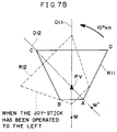
- FIG. 7B illustrates the display direction of the bird's-eye view map when the joy-stick 7a has been operated in the left direction.
- the display direction D12 is a direction obtained by rotating the display direction D11 to the left by (10 x n) degrees around the vehicle current position PV and the display range R12 is the area enclosed by the broken lines.
- the display direction D11 is the vehicle advancing direction, more of the road state on the left hand side relative to the advancing direction is displayed within the screen.
- FIGS. 7A and 7B clearly indicate, when the joy-stick 7a has not been operated, the viewpoint M is set in the sky on the opposite side of the current position PV of the vehicle, relative to the vehicle advancing direction D1.
- the viewpoint M' is set on the line D2 which intersects the line D1 connecting the viewpoint M and the current position PV on the current position PV at an angle (10 x n) degrees, which corresponds to the joy-stick operation, and is set in the sky on the opposite side of the current position relative to the display direction.
- the trapezoidal area ABCD rotates around the vehicle current position PV.
- the vehicle current position mark is always displayed at a constant position within the display screen.
- the trapezoidal area ABCD may be caused to rotate around the viewpoint M.
- the display position of the vehicle position mark on the display device 6 changes as the bird's-eye view map display direction is changed.
- FIG. 9 is a flowchart of the processing which interrupts when the current position button 7b has been operated.
- the operation remains in standby until the screen redraw is completed in step S901 and when the screen redraw ends, the operation proceeds to step S1, shown in FIG. 2 to execute the main processing described earlier. Consequently, even when the display direction of the bird's-eye view map is rotating to the left or right from the vehicle advancing direction by tilting the joy-stick 7a to the left or right, by operating the current position button 7b, the display of the bird's-eye view map is changed with the display direction being the vehicle advancing direction.
- the bird's-eye view map is displayed in the following manner.
- the control circuit 3 detects the current position and the advancing direction of the vehicle, and sets the look-down direction from the viewpoint, i.e., the display direction.
- road map data are read from the map storage memory 2 based upon the current position and the look-down direction.
- Data, the classification of which satisfies specific conditions, are extracted from the road map data thus read and the extracted data are converted to bird's-eye view map data.
- the bearing character notation indicating the display direction of the bird's-eye view map and the character notations that represent the two bearings adjacent to it are selected to create a set of bearing information image data.
- vehicle information image data required for displaying a vehicle mark to indicate the current position and the advancing direction of the vehicle are created.
- these data are displayed on the display device 6 before the current position of the vehicle position is detected again.
- FIG. 8A shows an example of display on the display device 6 when the vehicle advancing direction is set for the display direction in this manner.
- NW indicating north-west
- NE indicating north-east
- N the bearing of the vehicle advancing direction is north.
- filled triangles are displayed above and below the N to indicate that the vehicle advancing direction is north.
- FIG. 8A shows an example of a display when the display direction has been rotated in the clockwise direction relative to the vehicle advancing direction by tilting the joy-stick 7a to the right and more information is displayed in the range on the right hand side in the vehicle advancing direction.
- N indicating north, and E indicating east are displayed to the left and right of NE, which indicates north-east, i.e., the display direction of the bird's-eye view map. Note that the filled triangles are displayed above and below N indicating that the vehicle advancing direction is north.
- the bird's-eye view map is displayed on the display device, normally with the vehicle advancing direction set for the display direction and the bird's-eye view map is displayed with the display direction changed in correspondence to the operation of the joy-stick 7a being tilted to the left or right in this manner, road state in the range extending to the left and right relative to the vehicle advancing direction can be ascertained.
- the bearing information indicating the display direction of the bird's-eye view map is displayed along with the adjacent bearing information and also a mark for identifying the bearing of the vehicle advancing direction is added, making it possible to ascertain both the display direction of the bird's-eye view map and the vehicle advancing direction.
- a joy-stick that may be operated in 8 directions, i.e., up, down, left, right, diagonally upward to the right, diagonally downward to the right, diagonally upward to the left and diagonally downward to the left is used and the bird's-eye view map display is rotated only when the joy-stick 7a is operated to the left or the right, the display direction of the bird's-eye view map may be changed in the right direction when the joy-stick has been operated diagonally upward to the right or diagonally downward to the right and may be changed in the left direction when the joy-stick has been operated diagonally upward to the left or diagonally downward to the left.
- the display direction of the bird's-eye view map may be changed to a direction at once to which the joy-stick 7a is operated, that is a direction which the joy-stick 7a has designated among above mentioned 8 directions.
- a joy-stick can be operated more finely than the above-mentioned 8 directions and can output a signal corresponding to this operation, the bird's-eye view map can be rotated at once to the optional display direction.
- the operating member for changing the display direction of the bird's-eye view map is not limited to a joy-stick, and may be constituted with an operating button or an operating switch.
- the joy-stick 7a of the remote control device 7 is used to change the display direction of the bird's-eye view map, such an operating member may be provided at the display panel.
- the road map in the advancing direction of the vehicle is normally displayed as a bird's-eye view map
- the road map in the direction of the destination or the direction of the passing point located between the current position and the destination may be displayed as a bird's-eye view map.
Landscapes
- Engineering & Computer Science (AREA)
- Physics & Mathematics (AREA)
- Remote Sensing (AREA)
- Radar, Positioning & Navigation (AREA)
- General Physics & Mathematics (AREA)
- Theoretical Computer Science (AREA)
- Geometry (AREA)
- Computer Graphics (AREA)
- Automation & Control Theory (AREA)
- Software Systems (AREA)
- Computing Systems (AREA)
- Navigation (AREA)
- Instructional Devices (AREA)
- Traffic Control Systems (AREA)
Applications Claiming Priority (3)
| Application Number | Priority Date | Filing Date | Title |
|---|---|---|---|
| JP143684/95 | 1995-06-09 | ||
| JP7143684A JPH08335038A (ja) | 1995-06-09 | 1995-06-09 | 車両用地図表示装置 |
| JP14368495 | 1995-06-09 |
Publications (3)
| Publication Number | Publication Date |
|---|---|
| EP0747863A2 true EP0747863A2 (de) | 1996-12-11 |
| EP0747863A3 EP0747863A3 (de) | 1997-02-05 |
| EP0747863B1 EP0747863B1 (de) | 2003-01-29 |
Family
ID=15344551
Family Applications (1)
| Application Number | Title | Priority Date | Filing Date |
|---|---|---|---|
| EP96304297A Expired - Lifetime EP0747863B1 (de) | 1995-06-09 | 1996-06-07 | Kartenanzeigegerät |
Country Status (5)
| Country | Link |
|---|---|
| US (1) | US5941932A (de) |
| EP (1) | EP0747863B1 (de) |
| JP (1) | JPH08335038A (de) |
| KR (1) | KR100255523B1 (de) |
| DE (1) | DE69625957T2 (de) |
Cited By (2)
| Publication number | Priority date | Publication date | Assignee | Title |
|---|---|---|---|---|
| EP0802516A3 (de) * | 1996-04-16 | 1997-12-29 | Xanavi Informatics Corporation | Karten-Anzeigegerät, Navigationsgerät und Karten-Anzeigeverfahren |
| WO2006111461A1 (de) * | 2005-04-19 | 2006-10-26 | Robert Bosch Gmbh | VERFAHREN ZUR DREIDIMENSIONALEN DARSTELLUNG EINER DIGITALEN STRAßENKARTE |
Families Citing this family (11)
| Publication number | Priority date | Publication date | Assignee | Title |
|---|---|---|---|---|
| JP3568621B2 (ja) | 1995-04-20 | 2004-09-22 | 株式会社日立製作所 | 地図表示装置 |
| US6046689A (en) * | 1998-11-12 | 2000-04-04 | Newman; Bryan | Historical simulator |
| JP2001221643A (ja) * | 2000-02-04 | 2001-08-17 | Pioneer Electronic Corp | カーナビゲーションシステムからの地図情報切り出し装置 |
| US6536123B2 (en) | 2000-10-16 | 2003-03-25 | Sensation, Inc. | Three-axis magnetic sensor, an omnidirectional magnetic sensor and an azimuth measuring method using the same |
| JP4597496B2 (ja) | 2003-09-04 | 2010-12-15 | 三菱電機株式会社 | 表示装置 |
| US8751156B2 (en) | 2004-06-30 | 2014-06-10 | HERE North America LLC | Method of operating a navigation system using images |
| US7460953B2 (en) | 2004-06-30 | 2008-12-02 | Navteq North America, Llc | Method of operating a navigation system using images |
| US20060114893A1 (en) * | 2004-11-29 | 2006-06-01 | Timo Tokkonen | Updating associating data in a media device |
| US8108142B2 (en) * | 2005-01-26 | 2012-01-31 | Volkswagen Ag | 3D navigation system for motor vehicles |
| WO2006121986A2 (en) | 2005-05-06 | 2006-11-16 | Facet Technology Corp. | Network-based navigation system having virtual drive-thru advertisements integrated with actual imagery from along a physical route |
| WO2023074662A1 (ja) * | 2021-10-28 | 2023-05-04 | 日本精機株式会社 | 表示制御装置、ヘッドアップディスプレイ装置、及び表示制御方法 |
Family Cites Families (10)
| Publication number | Priority date | Publication date | Assignee | Title |
|---|---|---|---|---|
| US3885325A (en) * | 1971-08-03 | 1975-05-27 | Electronic Associates | Flight simulator |
| JPS57169785A (en) * | 1981-04-13 | 1982-10-19 | Nissan Motor | Travelling guidance system for car |
| FR2610752B1 (fr) * | 1987-02-10 | 1989-07-21 | Sagem | Procede de representation de l'image en perspective d'un terrain et systeme pour sa mise en oeuvre |
| FR2634707B1 (fr) * | 1988-07-28 | 1993-02-05 | Peugeot | Dispositif d'aide a la navigation d'un vehicule notamment automobile |
| NL8900056A (nl) * | 1989-01-11 | 1990-08-01 | Philips Nv | Werkwijze voor het visueel weergeven van een deel van een topografische kaart, alsmede inrichting geschikt voor een dergelijke werkwijze. |
| JP2853747B2 (ja) * | 1990-01-31 | 1999-02-03 | アルパイン 株式会社 | 地図描画方法 |
| DE69434693T2 (de) * | 1993-12-27 | 2006-08-24 | Nissan Motor Co., Ltd., Yokohama | Fahrzeugzielführungsvorrichtung und -verfahren unter Verwendung einer Anzeigeeinheit |
| EP0678731B1 (de) * | 1994-04-15 | 1999-06-30 | Nissan Motor Co., Ltd. | Fahrzeug-Navigationssystem |
| DE19544921C2 (de) * | 1994-12-02 | 1998-10-29 | Nissan Motor | Vorrichtung und Verfahren für die Navigation eines mobilen Körpers unter Verwendung einer aus der Vogelperspektive angezeigten Straßenkarte |
| JP3371605B2 (ja) * | 1995-04-19 | 2003-01-27 | 日産自動車株式会社 | 大気効果表示機能付き鳥瞰図表示ナビゲーションシステム |
-
1995
- 1995-06-09 JP JP7143684A patent/JPH08335038A/ja active Pending
-
1996
- 1996-06-07 EP EP96304297A patent/EP0747863B1/de not_active Expired - Lifetime
- 1996-06-07 DE DE69625957T patent/DE69625957T2/de not_active Expired - Lifetime
- 1996-06-07 US US08/660,407 patent/US5941932A/en not_active Expired - Lifetime
- 1996-06-10 KR KR1019960021340A patent/KR100255523B1/ko not_active Expired - Lifetime
Cited By (8)
| Publication number | Priority date | Publication date | Assignee | Title |
|---|---|---|---|---|
| EP0802516A3 (de) * | 1996-04-16 | 1997-12-29 | Xanavi Informatics Corporation | Karten-Anzeigegerät, Navigationsgerät und Karten-Anzeigeverfahren |
| US6169552B1 (en) | 1996-04-16 | 2001-01-02 | Xanavi Informatics Corporation | Map display device, navigation device and map display method |
| EP1426910A3 (de) * | 1996-04-16 | 2006-11-02 | Xanavi Informatics Corporation | karten-Anzeigegerät, Navigationsgerät und Karten-Anzeigeverfahren |
| EP1460604A3 (de) * | 1996-04-16 | 2006-11-02 | Xanavi Informatics Corporation | Karten-Anzeigegerät, Navigationsgerät und Karten-Anzeigeverfahren |
| WO2006111461A1 (de) * | 2005-04-19 | 2006-10-26 | Robert Bosch Gmbh | VERFAHREN ZUR DREIDIMENSIONALEN DARSTELLUNG EINER DIGITALEN STRAßENKARTE |
| US20100063728A1 (en) * | 2005-04-19 | 2010-03-11 | Thomas Jung | Method for the Three-Dimensional Representation of a Digital Roadmap |
| US8442762B2 (en) * | 2005-04-19 | 2013-05-14 | Robert Bosch Gmbh | Method for the three-dimensional representation of a digital roadmap |
| CN101163943B (zh) * | 2005-04-19 | 2016-03-23 | 罗伯特·博世有限公司 | 用于三维显示数字公路图的方法 |
Also Published As
| Publication number | Publication date |
|---|---|
| KR100255523B1 (ko) | 2000-05-01 |
| DE69625957D1 (de) | 2003-03-06 |
| KR970002800A (ko) | 1997-01-28 |
| US5941932A (en) | 1999-08-24 |
| JPH08335038A (ja) | 1996-12-17 |
| EP0747863A3 (de) | 1997-02-05 |
| DE69625957T2 (de) | 2003-11-13 |
| EP0747863B1 (de) | 2003-01-29 |
Similar Documents
| Publication | Publication Date | Title |
|---|---|---|
| US6012014A (en) | Map display apparatus for motor vehicle | |
| KR0184700B1 (ko) | 차량용 지도표시장치 | |
| JP3898677B2 (ja) | 車両用ナビゲーション装置 | |
| US5941932A (en) | Map display apparatus | |
| JP2009145100A (ja) | ナビゲーション装置 | |
| JPH1183511A (ja) | 車両用走行経路案内装置及び記憶媒体 | |
| JP2000003497A (ja) | 走行位置表示装置 | |
| US20250044114A1 (en) | Image control program, image control device, and image control method | |
| JP3594673B2 (ja) | 交通情報表示装置 | |
| JP3452672B2 (ja) | 地図表示制御方法および地図表示装置 | |
| JP2004108894A (ja) | カーナビゲーション装置 | |
| JP3604493B2 (ja) | 地図表示装置 | |
| JPH08145702A (ja) | 地図表示装置 | |
| EP1134552B1 (de) | Mobile Navigationsvorrichtung | |
| JP3386604B2 (ja) | 地図表示方法および地図表示装置 | |
| JP3278897B2 (ja) | 移動体用ナビゲーション装置 | |
| JPH032617A (ja) | 車載用ナビゲーション装置 | |
| JP3371433B2 (ja) | 移動体用ナビゲーション装置 | |
| JP2870866B2 (ja) | 車両の走行誘導装置 | |
| JP2002243491A (ja) | 車両用地図表示装置 | |
| JPH06195023A (ja) | 車載ナビゲータの地図描画方法 | |
| JP2002236030A (ja) | 車両用地図表示装置 | |
| JP2002206928A (ja) | 車両用地図表示装置 | |
| JP2002267481A (ja) | 車両用地図表示装置 | |
| JPH08285617A (ja) | ナビゲーション装置 |
Legal Events
| Date | Code | Title | Description |
|---|---|---|---|
| PUAI | Public reference made under article 153(3) epc to a published international application that has entered the european phase |
Free format text: ORIGINAL CODE: 0009012 |
|
| AK | Designated contracting states |
Kind code of ref document: A2 Designated state(s): DE FR GB |
|
| PUAL | Search report despatched |
Free format text: ORIGINAL CODE: 0009013 |
|
| AK | Designated contracting states |
Kind code of ref document: A3 Designated state(s): DE FR GB |
|
| 17P | Request for examination filed |
Effective date: 19970618 |
|
| 17Q | First examination report despatched |
Effective date: 20000302 |
|
| GRAG | Despatch of communication of intention to grant |
Free format text: ORIGINAL CODE: EPIDOS AGRA |
|
| GRAG | Despatch of communication of intention to grant |
Free format text: ORIGINAL CODE: EPIDOS AGRA |
|
| GRAH | Despatch of communication of intention to grant a patent |
Free format text: ORIGINAL CODE: EPIDOS IGRA |
|
| GRAH | Despatch of communication of intention to grant a patent |
Free format text: ORIGINAL CODE: EPIDOS IGRA |
|
| GRAA | (expected) grant |
Free format text: ORIGINAL CODE: 0009210 |
|
| AK | Designated contracting states |
Designated state(s): DE FR GB |
|
| REG | Reference to a national code |
Ref country code: GB Ref legal event code: FG4D |
|
| REF | Corresponds to: |
Ref document number: 69625957 Country of ref document: DE Date of ref document: 20030306 Kind code of ref document: P |
|
| ET | Fr: translation filed | ||
| PLBE | No opposition filed within time limit |
Free format text: ORIGINAL CODE: 0009261 |
|
| STAA | Information on the status of an ep patent application or granted ep patent |
Free format text: STATUS: NO OPPOSITION FILED WITHIN TIME LIMIT |
|
| 26N | No opposition filed |
Effective date: 20031030 |
|
| REG | Reference to a national code |
Ref country code: DE Ref legal event code: R082 Ref document number: 69625957 Country of ref document: DE Representative=s name: BEETZ & PARTNER PATENT- UND RECHTSANWAELTE, DE |
|
| REG | Reference to a national code |
Ref country code: GB Ref legal event code: 732E Free format text: REGISTERED BETWEEN 20140417 AND 20140423 |
|
| REG | Reference to a national code |
Ref country code: FR Ref legal event code: TP Owner name: CLARION CO., LTD., JP Effective date: 20140604 |
|
| REG | Reference to a national code |
Ref country code: DE Ref legal event code: R079 Ref document number: 69625957 Country of ref document: DE Free format text: PREVIOUS MAIN CLASS: G06T0017500000 Ipc: G06T0017050000 |
|
| REG | Reference to a national code |
Ref country code: DE Ref legal event code: R082 Ref document number: 69625957 Country of ref document: DE Representative=s name: BEETZ & PARTNER MBB PATENT- UND RECHTSANWAELTE, DE Effective date: 20140311 Ref country code: DE Ref legal event code: R082 Ref document number: 69625957 Country of ref document: DE Representative=s name: BEETZ & PARTNER MBB PATENTANWAELTE, DE Effective date: 20140311 Ref country code: DE Ref legal event code: R082 Ref document number: 69625957 Country of ref document: DE Representative=s name: BEETZ & PARTNER MBB, DE Effective date: 20140311 Ref country code: DE Ref legal event code: R082 Ref document number: 69625957 Country of ref document: DE Representative=s name: BEETZ & PARTNER PATENT- UND RECHTSANWAELTE, DE Effective date: 20140311 Ref country code: DE Ref legal event code: R081 Ref document number: 69625957 Country of ref document: DE Owner name: CLARION CO., LTD., SAITAMA-SHI, JP Free format text: FORMER OWNER: XANAVI INFORMATICS CORP., ZAMA-SHI, KANAGAWA, JP Effective date: 20140311 Ref country code: DE Ref legal event code: R079 Ref document number: 69625957 Country of ref document: DE Free format text: PREVIOUS MAIN CLASS: G06T0017500000 Ipc: G06T0017050000 Effective date: 20141106 |
|
| REG | Reference to a national code |
Ref country code: FR Ref legal event code: PLFP Year of fee payment: 20 |
|
| PGFP | Annual fee paid to national office [announced via postgrant information from national office to epo] |
Ref country code: DE Payment date: 20150602 Year of fee payment: 20 Ref country code: GB Payment date: 20150603 Year of fee payment: 20 |
|
| PGFP | Annual fee paid to national office [announced via postgrant information from national office to epo] |
Ref country code: FR Payment date: 20150608 Year of fee payment: 20 |
|
| REG | Reference to a national code |
Ref country code: DE Ref legal event code: R071 Ref document number: 69625957 Country of ref document: DE |
|
| REG | Reference to a national code |
Ref country code: GB Ref legal event code: PE20 Expiry date: 20160606 |
|
| PG25 | Lapsed in a contracting state [announced via postgrant information from national office to epo] |
Ref country code: GB Free format text: LAPSE BECAUSE OF EXPIRATION OF PROTECTION Effective date: 20160606 |