EP0749087A2 - Commutateur électrique pour utilisation dans un véhicule automobile - Google Patents
Commutateur électrique pour utilisation dans un véhicule automobile Download PDFInfo
- Publication number
- EP0749087A2 EP0749087A2 EP96302296A EP96302296A EP0749087A2 EP 0749087 A2 EP0749087 A2 EP 0749087A2 EP 96302296 A EP96302296 A EP 96302296A EP 96302296 A EP96302296 A EP 96302296A EP 0749087 A2 EP0749087 A2 EP 0749087A2
- Authority
- EP
- European Patent Office
- Prior art keywords
- actuator
- electrical switch
- steering column
- carrier
- switch
- Prior art date
- Legal status (The legal status is an assumption and is not a legal conclusion. Google has not performed a legal analysis and makes no representation as to the accuracy of the status listed.)
- Withdrawn
Links
- NJPPVKZQTLUDBO-UHFFFAOYSA-N novaluron Chemical compound C1=C(Cl)C(OC(F)(F)C(OC(F)(F)F)F)=CC=C1NC(=O)NC(=O)C1=C(F)C=CC=C1F NJPPVKZQTLUDBO-UHFFFAOYSA-N 0.000 claims description 11
- 230000007246 mechanism Effects 0.000 claims description 9
- 230000006835 compression Effects 0.000 claims description 6
- 238000007906 compression Methods 0.000 claims description 6
- 230000013011 mating Effects 0.000 claims description 6
- 230000004044 response Effects 0.000 claims description 2
- 230000007935 neutral effect Effects 0.000 abstract description 4
- 238000002347 injection Methods 0.000 description 6
- 239000007924 injection Substances 0.000 description 6
- 229920002292 Nylon 6 Polymers 0.000 description 5
- 238000010276 construction Methods 0.000 description 5
- 239000011521 glass Substances 0.000 description 4
- RYGMFSIKBFXOCR-UHFFFAOYSA-N Copper Chemical compound [Cu] RYGMFSIKBFXOCR-UHFFFAOYSA-N 0.000 description 3
- 229920006102 Zytel® Polymers 0.000 description 3
- 229910052802 copper Inorganic materials 0.000 description 3
- 239000010949 copper Substances 0.000 description 3
- 239000000463 material Substances 0.000 description 3
- 238000010586 diagram Methods 0.000 description 2
- 238000000034 method Methods 0.000 description 2
- 230000008569 process Effects 0.000 description 2
- UTPYTEWRMXITIN-YDWXAUTNSA-N 1-methyl-3-[(e)-[(3e)-3-(methylcarbamothioylhydrazinylidene)butan-2-ylidene]amino]thiourea Chemical compound CNC(=S)N\N=C(/C)\C(\C)=N\NC(=S)NC UTPYTEWRMXITIN-YDWXAUTNSA-N 0.000 description 1
- 239000011190 CEM-3 Substances 0.000 description 1
- 229920006051 Capron® Polymers 0.000 description 1
- 229910000975 Carbon steel Inorganic materials 0.000 description 1
- 229920006074 Nylatron® Polymers 0.000 description 1
- 230000009471 action Effects 0.000 description 1
- DMFGNRRURHSENX-UHFFFAOYSA-N beryllium copper Chemical compound [Be].[Cu] DMFGNRRURHSENX-UHFFFAOYSA-N 0.000 description 1
- 230000015572 biosynthetic process Effects 0.000 description 1
- 239000010962 carbon steel Substances 0.000 description 1
- 230000000994 depressogenic effect Effects 0.000 description 1
- 238000009713 electroplating Methods 0.000 description 1
- 229910052500 inorganic mineral Inorganic materials 0.000 description 1
- 238000003780 insertion Methods 0.000 description 1
- 230000037431 insertion Effects 0.000 description 1
- 230000010354 integration Effects 0.000 description 1
- 238000004519 manufacturing process Methods 0.000 description 1
- 229910052751 metal Inorganic materials 0.000 description 1
- 239000002184 metal Substances 0.000 description 1
- 239000011707 mineral Substances 0.000 description 1
- 238000012986 modification Methods 0.000 description 1
- 230000004048 modification Effects 0.000 description 1
- CWQXQMHSOZUFJS-UHFFFAOYSA-N molybdenum disulfide Chemical compound S=[Mo]=S CWQXQMHSOZUFJS-UHFFFAOYSA-N 0.000 description 1
- 229910052982 molybdenum disulfide Inorganic materials 0.000 description 1
- KERTUBUCQCSNJU-UHFFFAOYSA-L nickel(2+);disulfamate Chemical compound [Ni+2].NS([O-])(=O)=O.NS([O-])(=O)=O KERTUBUCQCSNJU-UHFFFAOYSA-L 0.000 description 1
- 230000002093 peripheral effect Effects 0.000 description 1
Images


Classifications
-
- B—PERFORMING OPERATIONS; TRANSPORTING
- B60—VEHICLES IN GENERAL
- B60Q—ARRANGEMENT OF SIGNALLING OR LIGHTING DEVICES, THE MOUNTING OR SUPPORTING THEREOF OR CIRCUITS THEREFOR, FOR VEHICLES IN GENERAL
- B60Q1/00—Arrangement of optical signalling or lighting devices, the mounting or supporting thereof or circuits therefor
- B60Q1/02—Arrangement of optical signalling or lighting devices, the mounting or supporting thereof or circuits therefor the devices being primarily intended to illuminate the way ahead or to illuminate other areas of way or environments
- B60Q1/04—Arrangement of optical signalling or lighting devices, the mounting or supporting thereof or circuits therefor the devices being primarily intended to illuminate the way ahead or to illuminate other areas of way or environments the devices being headlights
- B60Q1/14—Arrangement of optical signalling or lighting devices, the mounting or supporting thereof or circuits therefor the devices being primarily intended to illuminate the way ahead or to illuminate other areas of way or environments the devices being headlights having dimming means
- B60Q1/1446—Arrangement of optical signalling or lighting devices, the mounting or supporting thereof or circuits therefor the devices being primarily intended to illuminate the way ahead or to illuminate other areas of way or environments the devices being headlights having dimming means controlled by mechanically actuated switches
- B60Q1/1453—Hand actuated switches
- B60Q1/1461—Multifunction switches for dimming headlights and controlling additional devices, e.g. for controlling direction indicating lights
- B60Q1/1469—Multifunction switches for dimming headlights and controlling additional devices, e.g. for controlling direction indicating lights controlled by or attached to a single lever, e.g. steering column stalk switches
-
- B—PERFORMING OPERATIONS; TRANSPORTING
- B60—VEHICLES IN GENERAL
- B60Q—ARRANGEMENT OF SIGNALLING OR LIGHTING DEVICES, THE MOUNTING OR SUPPORTING THEREOF OR CIRCUITS THEREFOR, FOR VEHICLES IN GENERAL
- B60Q1/00—Arrangement of optical signalling or lighting devices, the mounting or supporting thereof or circuits therefor
- B60Q1/26—Arrangement of optical signalling or lighting devices, the mounting or supporting thereof or circuits therefor the devices being primarily intended to indicate the vehicle, or parts thereof, or to give signals, to other traffic
- B60Q1/34—Arrangement of optical signalling or lighting devices, the mounting or supporting thereof or circuits therefor the devices being primarily intended to indicate the vehicle, or parts thereof, or to give signals, to other traffic for indicating change of drive direction
- B60Q1/40—Arrangement of optical signalling or lighting devices, the mounting or supporting thereof or circuits therefor the devices being primarily intended to indicate the vehicle, or parts thereof, or to give signals, to other traffic for indicating change of drive direction having mechanical, electric or electronic automatic return to inoperative position
- B60Q1/42—Arrangement of optical signalling or lighting devices, the mounting or supporting thereof or circuits therefor the devices being primarily intended to indicate the vehicle, or parts thereof, or to give signals, to other traffic for indicating change of drive direction having mechanical, electric or electronic automatic return to inoperative position having mechanical automatic return to inoperative position due to steering-wheel position, e.g. with roller wheel control
- B60Q1/425—Arrangement of optical signalling or lighting devices, the mounting or supporting thereof or circuits therefor the devices being primarily intended to indicate the vehicle, or parts thereof, or to give signals, to other traffic for indicating change of drive direction having mechanical, electric or electronic automatic return to inoperative position having mechanical automatic return to inoperative position due to steering-wheel position, e.g. with roller wheel control using a latching element for resetting a switching element
-
- G—PHYSICS
- G05—CONTROLLING; REGULATING
- G05G—CONTROL DEVICES OR SYSTEMS INSOFAR AS CHARACTERISED BY MECHANICAL FEATURES ONLY
- G05G9/00—Manually-actuated control mechanisms provided with one single controlling member co-operating with two or more controlled members, e.g. selectively, simultaneously
- G05G9/02—Manually-actuated control mechanisms provided with one single controlling member co-operating with two or more controlled members, e.g. selectively, simultaneously the controlling member being movable in different independent ways, movement in each individual way actuating one controlled member only
- G05G9/04—Manually-actuated control mechanisms provided with one single controlling member co-operating with two or more controlled members, e.g. selectively, simultaneously the controlling member being movable in different independent ways, movement in each individual way actuating one controlled member only in which movement in two or more ways can occur simultaneously
- G05G9/047—Manually-actuated control mechanisms provided with one single controlling member co-operating with two or more controlled members, e.g. selectively, simultaneously the controlling member being movable in different independent ways, movement in each individual way actuating one controlled member only in which movement in two or more ways can occur simultaneously the controlling member being movable by hand about orthogonal axes, e.g. joysticks
- G05G9/04785—Manually-actuated control mechanisms provided with one single controlling member co-operating with two or more controlled members, e.g. selectively, simultaneously the controlling member being movable in different independent ways, movement in each individual way actuating one controlled member only in which movement in two or more ways can occur simultaneously the controlling member being movable by hand about orthogonal axes, e.g. joysticks the controlling member being the operating part of a switch arrangement
- G05G9/04788—Manually-actuated control mechanisms provided with one single controlling member co-operating with two or more controlled members, e.g. selectively, simultaneously the controlling member being movable in different independent ways, movement in each individual way actuating one controlled member only in which movement in two or more ways can occur simultaneously the controlling member being movable by hand about orthogonal axes, e.g. joysticks the controlling member being the operating part of a switch arrangement comprising additional control elements
- G05G9/04796—Manually-actuated control mechanisms provided with one single controlling member co-operating with two or more controlled members, e.g. selectively, simultaneously the controlling member being movable in different independent ways, movement in each individual way actuating one controlled member only in which movement in two or more ways can occur simultaneously the controlling member being movable by hand about orthogonal axes, e.g. joysticks the controlling member being the operating part of a switch arrangement comprising additional control elements for rectilinear control along the axis of the controlling member
Definitions
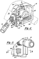
- an electrical switch for use in an automotive vehicle includes an actuator and a carrier movable to electrically actuate a steering column tilting device and a steering column telescoping device.
- a post and a receptacle assist to align the carrier during its linear switching movement.
- an actuator assembly is provided which includes a shaft, a partially spherical ball, a first set of crossed arms and a second set of crossed arms.
- Still another aspect of the present invention employs a centering spring for biasing an actuator toward a centralized neutral position.
- a modularized electrical switch is mechanically and electrically connected to a second circuit and housing in a single assembly motion.
- the electrical switch of the present invention is advantageous over traditional devices in that the present invention is more cost effective to manufacture and assemble. Furthermore, the present invention electrical switch achieves an integration of switching functions, electrical connection and mechanical attachment, both internally and externally, thereby improving electrical and mechanical reliability. Furthermore, the present invention reduces undesirable free play and imparts a higher quality and accurate switching feel. Additional advantages and features of the present invention will become apparent from the following description and appended claims, taken in conjunction with the accompanying drawings.
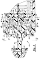
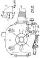
- a T-shaped formation 191 projects from an external surface of an upstanding wall 175 for sliding engagement with a slotted receiving structure 193 of cover 40.
- a pair of longitudinal depressions are also juxtaposed adjacent to the slot within cover 40. This provides a dovetailing mechanical attachment means.
- a flexible snap-fit finger 195 flexibly extends from base 173 of housing 71.
- a barb located on a distal end of snap-fit finger 195 engages in a tool free and quick connect manner with a rib 197 integrally injection molded within cover 40.
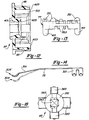
- housing 71 further has a post 211 internally extending from face 173.
- Post 211 passes through a clearance hole 213 within printed circuit board 73 and engages within a receptacle 215 disposed on a lower surface of carrier 77.
- Receptacle 215 has a pair of crossing grooves 217 coinciding with cross-like aperture 61 (see Figure 1) of bezel 59 (also see Figure 1).
- post 211 acts to supplementally support a corner of carrier 77 and to assist in aligning carrier 77 during its linear movement.
- Housing 71 is preferably injection molded from 13% glass reinforced nylon 6/6 such as DuPont Zytel®.
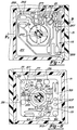
- a guide 231 is integrally formed centrally upon an interior surface of base 173 of housing 71.
- Guide 231 has a pair of crossed grooves 233 which intersect at a depressed detent 235.
- Grooves 233 of guide 231 are aligned with grooves 217 (see Figure 7) of carrier 77 and cross-like aperture 61 (see Figure 1) of bezel 59 (also see Figure 1).
- a rounded end of plunger 81 rides along grooves 233 and detent 235.
- electrical connector 271 is soldered to paths 253 at location 273.
- a pair of generally stiff and elongated male terminal blades 275 project from electrical connector 271 for engagement within a mating electrical connector 277 soldered upon main circuit board 47.
- a polymeric snap-fit finger 279 also projects from electrical connector 271 for flexibly engaging into a depression within an exterior surface of mating connector 277.
- the electrical connection is made simultaneously with mechanically fastening electrical switch 71 to cover 40. Additional discretely wired pigtails, electrical connectors, the associated assembly costs, access and reliability problems are thereby eliminated.
- the switch housing may be omitted altogether such that the tilting/telescoping printed circuit board is integrated into the main turn signal printed circuit board with the other switch components riding directly thereupon.
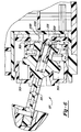
- An upper set of bearing surfaces 421 extend from carrier 77 for movably riding along lower corner surfaces 423 of cover 87.
- Carrier 77 is preferably made from 13% glass reinforced nylon 6/6 such as DuPont Zytel®.
- Lower set of arms 361 of actuator 85 have either a cylindrical or frusto conical shape thereto of varying diameters in order to provide a keyholed alignment during assembly.
- a median set of crossed arms 383 project in a transverse manner from an upper portion of pedestal 381. Ribs 385 span between pedestal 381 and median arms 383. These median arms 383 are substantially aligned with lower arms 361. Centering compression spring 79 is compressibly trapped between arms 383 and carrier 77 thereby providing a biased centering action for moving actuator 85 toward the neutral and unswitched position, as shown in Figure 5. Centering spring 79 further reduces the undesirable free play and sloppy movement found in many conventional switch designs. Centering spring 79 is preferably made from music wire ATSM A228 and has three active coils.
Landscapes
- Engineering & Computer Science (AREA)
- Mechanical Engineering (AREA)
- Physics & Mathematics (AREA)
- General Physics & Mathematics (AREA)
- Automation & Control Theory (AREA)
- Switches With Compound Operations (AREA)
Applications Claiming Priority (2)
| Application Number | Priority Date | Filing Date | Title |
|---|---|---|---|
| US431899 | 1995-05-01 | ||
| US08/431,899 US5744769A (en) | 1993-09-13 | 1995-05-01 | Electrical switch for use in an automotive vehicle |
Publications (1)
| Publication Number | Publication Date |
|---|---|
| EP0749087A2 true EP0749087A2 (fr) | 1996-12-18 |
Family
ID=23713908
Family Applications (1)
| Application Number | Title | Priority Date | Filing Date |
|---|---|---|---|
| EP96302296A Withdrawn EP0749087A2 (fr) | 1995-05-01 | 1996-04-01 | Commutateur électrique pour utilisation dans un véhicule automobile |
Country Status (3)
| Country | Link |
|---|---|
| US (1) | US5744769A (fr) |
| EP (1) | EP0749087A2 (fr) |
| JP (1) | JPH08339737A (fr) |
Cited By (1)
| Publication number | Priority date | Publication date | Assignee | Title |
|---|---|---|---|---|
| EP1069488A3 (fr) * | 1999-07-14 | 2004-07-28 | Alps Electric Co., Ltd. | Dispositif d'entrée de données monté dans un véhicule |
Families Citing this family (15)
| Publication number | Priority date | Publication date | Assignee | Title |
|---|---|---|---|---|
| JP3734110B2 (ja) * | 1996-06-21 | 2006-01-11 | 矢崎総業株式会社 | ステアリングモジュール |
| DE19732232A1 (de) * | 1997-07-26 | 1999-01-28 | Eaton Controls Gmbh | Lenkstockschalter |
| DE19931994A1 (de) * | 1999-07-09 | 2001-01-11 | Eaton Corp | Lenkstockschalter |
| US6349611B1 (en) | 2000-03-20 | 2002-02-26 | L & P Property Management Company | Cable operated actuator assembly |
| US20070048727A1 (en) * | 2001-04-25 | 2007-03-01 | Michael Shuler | Biliary barrier |
| JP2003263938A (ja) * | 2002-03-07 | 2003-09-19 | Matsushita Electric Ind Co Ltd | レバースイッチ及びこれを用いた複合スイッチ |
| DE10211807A1 (de) * | 2002-03-16 | 2003-10-09 | Delphi Tech Inc | Lenkstockschalter für ein Kraftfahrzeug |
| US6844510B2 (en) * | 2002-08-09 | 2005-01-18 | Stonebridge Control Devices, Inc. | Stalk switch |
| JP2005100227A (ja) * | 2003-09-26 | 2005-04-14 | Niles Co Ltd | 操作レバー構造 |
| US7005592B2 (en) * | 2003-10-15 | 2006-02-28 | Methode Electronics, Inc. | Plunger contact assembly for an automobile control stalk |
| US6903283B2 (en) * | 2003-10-17 | 2005-06-07 | Honeywell International Inc. | Plunger retention apparatus and method for switch enclosures |
| DE10350232A1 (de) * | 2003-10-27 | 2005-05-19 | Behr Gmbh & Co. Kg | Luftausströmer für Kraftfahrzeuge |
| DE102010063868A1 (de) * | 2010-12-22 | 2012-06-28 | Kiekert Ag | Verstärktes Kraftfahrzeugschloss |
| CN103617914A (zh) * | 2013-12-02 | 2014-03-05 | 昌辉汽车电器(黄山)股份公司 | 一种簧片式四向微动开关 |
| DE102016213501A1 (de) * | 2016-07-22 | 2018-01-25 | Continental Automotive Gmbh | Füllstandsgeber |
Citations (6)
| Publication number | Priority date | Publication date | Assignee | Title |
|---|---|---|---|---|
| US4599500A (en) | 1985-04-01 | 1986-07-08 | Chrysler Corporation | Tilt steering column head mounted switch operating control |
| US4753121A (en) | 1987-05-05 | 1988-06-28 | Trw Inc. | Tilt-telescope steering column |
| US4793204A (en) | 1987-11-25 | 1988-12-27 | Douglas Components Corporation | Tilt and telescope steering column having a single control |
| US4981049A (en) | 1988-11-29 | 1991-01-01 | Trw Inc. | Tilt-telescope steering column |
| USRE34359E (en) | 1987-04-17 | 1993-08-31 | Nippon Seiko Kabushiki Kaisha | Electric steering apparatus |
| US5269562A (en) | 1991-02-06 | 1993-12-14 | Mercedes-Benz Ag | Axially adjustable steering column for vehicles |
Family Cites Families (32)
| Publication number | Priority date | Publication date | Assignee | Title |
|---|---|---|---|---|
| FR1345468A (fr) * | 1963-01-25 | 1963-12-06 | Lucas Industries Ltd | Commutateur de changement de direction pour véhicule |
| JPS5223255Y2 (fr) * | 1972-09-28 | 1977-05-27 | ||
| US3914566A (en) * | 1973-01-12 | 1975-10-21 | Int Harvester Co | Turn signal and hazard warning switch |
| US3814871A (en) * | 1973-03-21 | 1974-06-04 | Mc Gill Mfg Co | Joystick controller for multiple switch assembly |
| FR2246171A5 (fr) * | 1973-09-28 | 1975-04-25 | Jaeger | |
| FR2262474A1 (en) * | 1974-02-22 | 1975-09-19 | Citroen Sa | Control unit for vehicle electrics - has selective switch functions and single operating stem |
| US3988558A (en) * | 1975-05-28 | 1976-10-26 | Cutler-Hammer, Inc. | Toggle switch having an easily assembled, anti-rotation mounting means for its pivotal toggle lever |
| JPS558661Y2 (fr) * | 1975-10-27 | 1980-02-26 | ||
| US4280027A (en) * | 1980-05-27 | 1981-07-21 | The Singer Company | Switch blade mechanism and multi-arrangement |
| US4426951A (en) * | 1981-09-14 | 1984-01-24 | Nihon Plast Co., Ltd. | Turn signal cancellation apparatus for use with steering wheel and shaft assembly |
| DE3146271C2 (de) * | 1981-11-21 | 1985-03-14 | Franz Kirsten Elektrotechnische Spezialfabrik, 6530 Bingen | Kraftfahrzeug-Lenkstockschalter mit Rückstellung |
| US4564732A (en) * | 1982-05-19 | 1986-01-14 | Hi-Tek Corporation | Dovetail base assembly for keyswitches |
| JPS58176039U (ja) * | 1982-05-20 | 1983-11-25 | 株式会社東海理化電機製作所 | タ−ンシグナルのセルフキヤンセル装置 |
| US4590341A (en) * | 1983-08-22 | 1986-05-20 | Kabushiki Kaisha Tokai-Rika-Denki-Seisakusho | Column mounted switching device |
| JPS6139648U (ja) * | 1984-08-16 | 1986-03-13 | 株式会社東海理化電機製作所 | 車両用方向指示操作レバ−の戻し装置 |
| JPH0322034Y2 (fr) * | 1986-04-07 | 1991-05-14 | ||
| US4721834A (en) * | 1986-04-30 | 1988-01-26 | Emhart Industries, Inc. | Lever control system |
| JPH079310Y2 (ja) * | 1986-06-16 | 1995-03-06 | アルプス電気株式会社 | タ−ンシグナルスイツチのキヤンセル機構 |
| US4816662A (en) * | 1986-08-07 | 1989-03-28 | Ichikoh Industries Limited | Remote control switch for posture adjustment of automotive mirrors |
| JP2512506B2 (ja) * | 1987-12-14 | 1996-07-03 | 株式会社東海理化電機製作所 | タ―ンシグナルのキャンセル装置 |
| US4900946A (en) * | 1988-06-03 | 1990-02-13 | Navistar International Transportation Corp. | Multi-function switch for automotive vehicles |
| DE3829109C2 (de) * | 1988-08-27 | 1998-02-26 | Teves Gmbh Alfred | Elektrischer Schalter, insbesondere Lenkstockschalter für Kraftfahrzeuge |
| JPH0621789Y2 (ja) * | 1989-02-22 | 1994-06-08 | 株式会社東海理化電機製作所 | ターンシグナルスイッチのセルフキャンセル装置 |
| US5068499A (en) * | 1989-04-14 | 1991-11-26 | Alps Electric Co., Ltd. | Control lever type input device |
| JPH037241U (fr) * | 1989-06-12 | 1991-01-24 | ||
| EP0419046B1 (fr) * | 1989-08-23 | 1997-05-28 | Japan Energy Corporation | Procédé et système de détection d'incendie et moniteur de l'environnement |
| JPH0422335U (fr) * | 1990-06-19 | 1992-02-25 | ||
| JP2565582Y2 (ja) * | 1990-07-18 | 1998-03-18 | 株式会社東海理化電機製作所 | レバースイッチ |
| US5187647A (en) * | 1991-03-11 | 1993-02-16 | John Fluke Mfg. Co., Inc. | Electronic instrument keypad assembly with z-axis oriented electrical interconnect |
| US5227594A (en) * | 1991-12-12 | 1993-07-13 | Guardian Electric Manufacturing Company | Electrical multi-directional switch |
| US5313028A (en) * | 1992-07-02 | 1994-05-17 | Itt Corporation | Turn signal cancel mechanism |
| US5385067A (en) * | 1993-09-13 | 1995-01-31 | United Technologies Automotive, Inc. | Turn signal cancellation mechanism |
-
1995
- 1995-05-01 US US08/431,899 patent/US5744769A/en not_active Expired - Lifetime
-
1996
- 1996-04-01 EP EP96302296A patent/EP0749087A2/fr not_active Withdrawn
- 1996-05-01 JP JP8110636A patent/JPH08339737A/ja active Pending
Patent Citations (6)
| Publication number | Priority date | Publication date | Assignee | Title |
|---|---|---|---|---|
| US4599500A (en) | 1985-04-01 | 1986-07-08 | Chrysler Corporation | Tilt steering column head mounted switch operating control |
| USRE34359E (en) | 1987-04-17 | 1993-08-31 | Nippon Seiko Kabushiki Kaisha | Electric steering apparatus |
| US4753121A (en) | 1987-05-05 | 1988-06-28 | Trw Inc. | Tilt-telescope steering column |
| US4793204A (en) | 1987-11-25 | 1988-12-27 | Douglas Components Corporation | Tilt and telescope steering column having a single control |
| US4981049A (en) | 1988-11-29 | 1991-01-01 | Trw Inc. | Tilt-telescope steering column |
| US5269562A (en) | 1991-02-06 | 1993-12-14 | Mercedes-Benz Ag | Axially adjustable steering column for vehicles |
Cited By (1)
| Publication number | Priority date | Publication date | Assignee | Title |
|---|---|---|---|---|
| EP1069488A3 (fr) * | 1999-07-14 | 2004-07-28 | Alps Electric Co., Ltd. | Dispositif d'entrée de données monté dans un véhicule |
Also Published As
| Publication number | Publication date |
|---|---|
| JPH08339737A (ja) | 1996-12-24 |
| US5744769A (en) | 1998-04-28 |
Similar Documents
| Publication | Publication Date | Title |
|---|---|---|
| EP0749087A2 (fr) | Commutateur électrique pour utilisation dans un véhicule automobile | |
| US4315113A (en) | Actuator switch for remote control rearview mirrors | |
| EP0807033B1 (fr) | Mecanisme d'arret des indicateurs de changement de direction | |
| US20070235315A1 (en) | Handle switch device of vehicle | |
| US6998546B1 (en) | Switch assembly for a vehicle | |
| US6384351B1 (en) | Switch apparatus for actuating a plurality of electrical circuits | |
| US6761084B2 (en) | Shift lever device | |
| US4816662A (en) | Remote control switch for posture adjustment of automotive mirrors | |
| US6118089A (en) | Modular steering column switch with selectable switching functions | |
| JP2003162945A (ja) | 車両用レバースイッチの構造 | |
| EP1093551A1 (fr) | Dispositif de manoeuvre | |
| US6396011B1 (en) | Multi-function switch lever apparatus | |
| US5041703A (en) | Mirror control switch for automotive vehicles | |
| US5708243A (en) | Multi-position, multi-directional electric switch mechanism | |
| US5107085A (en) | Clustered push button switches having sheet metal conductors formed with contact tabs | |
| US6759606B2 (en) | Membrane slide switch | |
| EP0747264A2 (fr) | Interrupteur électrique possédant un méchanisme rotatif pour véhicule automobile | |
| US4904828A (en) | Multi-circuit slide switch assembly with distinct plunger operated switch | |
| CN120418123A (zh) | 用于机动车的转向柱开关 | |
| US5111011A (en) | Mirror control slide switch for automotive vehicles | |
| US6903285B2 (en) | Steering column switch | |
| US6403899B1 (en) | Vehicle fog lamp interlock switch apparatus | |
| KR102675895B1 (ko) | 차량용 멀티 오퍼레이팅 스위치 유니트 | |
| US6921870B2 (en) | Shifting mechanism for electric vehicles | |
| US11953087B1 (en) | Shift lever device for electric vehicle |
Legal Events
| Date | Code | Title | Description |
|---|---|---|---|
| PUAI | Public reference made under article 153(3) epc to a published international application that has entered the european phase |
Free format text: ORIGINAL CODE: 0009012 |
|
| AK | Designated contracting states |
Kind code of ref document: A2 Designated state(s): DE ES FR GB IT SE |
|
| RAP1 | Party data changed (applicant data changed or rights of an application transferred) |
Owner name: UT AUTOMOTIVE DEARBORN, INC. |
|
| STAA | Information on the status of an ep patent application or granted ep patent |
Free format text: STATUS: THE APPLICATION HAS BEEN WITHDRAWN |
|
| 18W | Application withdrawn |
Withdrawal date: 19981224 |