EP0750140A2 - Gangschalt-Steuerungssystem - Google Patents
Gangschalt-Steuerungssystem Download PDFInfo
- Publication number
- EP0750140A2 EP0750140A2 EP96304500A EP96304500A EP0750140A2 EP 0750140 A2 EP0750140 A2 EP 0750140A2 EP 96304500 A EP96304500 A EP 96304500A EP 96304500 A EP96304500 A EP 96304500A EP 0750140 A2 EP0750140 A2 EP 0750140A2
- Authority
- EP
- European Patent Office
- Prior art keywords
- hydraulic
- synchromesh
- restriction
- actuator
- source
- Prior art date
- Legal status (The legal status is an assumption and is not a legal conclusion. Google has not performed a legal analysis and makes no representation as to the accuracy of the status listed.)
- Withdrawn
Links
Images

Classifications
-
- F—MECHANICAL ENGINEERING; LIGHTING; HEATING; WEAPONS; BLASTING
- F16—ENGINEERING ELEMENTS AND UNITS; GENERAL MEASURES FOR PRODUCING AND MAINTAINING EFFECTIVE FUNCTIONING OF MACHINES OR INSTALLATIONS; THERMAL INSULATION IN GENERAL
- F16H—GEARING
- F16H61/00—Control functions within control units of change-speed- or reversing-gearings for conveying rotary motion ; Control of exclusively fluid gearing, friction gearing, gearings with endless flexible members or other particular types of gearing
- F16H61/04—Smoothing ratio shift
- F16H61/0403—Synchronisation before shifting
-
- F—MECHANICAL ENGINEERING; LIGHTING; HEATING; WEAPONS; BLASTING
- F16—ENGINEERING ELEMENTS AND UNITS; GENERAL MEASURES FOR PRODUCING AND MAINTAINING EFFECTIVE FUNCTIONING OF MACHINES OR INSTALLATIONS; THERMAL INSULATION IN GENERAL
- F16H—GEARING
- F16H61/00—Control functions within control units of change-speed- or reversing-gearings for conveying rotary motion ; Control of exclusively fluid gearing, friction gearing, gearings with endless flexible members or other particular types of gearing
- F16H61/26—Generation or transmission of movements for final actuating mechanisms
- F16H61/28—Generation or transmission of movements for final actuating mechanisms with at least one movement of the final actuating mechanism being caused by a non-mechanical force, e.g. power-assisted
- F16H61/30—Hydraulic or pneumatic motors or related fluid control means therefor
-
- F—MECHANICAL ENGINEERING; LIGHTING; HEATING; WEAPONS; BLASTING
- F16—ENGINEERING ELEMENTS AND UNITS; GENERAL MEASURES FOR PRODUCING AND MAINTAINING EFFECTIVE FUNCTIONING OF MACHINES OR INSTALLATIONS; THERMAL INSULATION IN GENERAL
- F16H—GEARING
- F16H61/00—Control functions within control units of change-speed- or reversing-gearings for conveying rotary motion ; Control of exclusively fluid gearing, friction gearing, gearings with endless flexible members or other particular types of gearing
- F16H61/26—Generation or transmission of movements for final actuating mechanisms
- F16H61/28—Generation or transmission of movements for final actuating mechanisms with at least one movement of the final actuating mechanism being caused by a non-mechanical force, e.g. power-assisted
- F16H2061/2823—Controlling actuator force way characteristic, i.e. controlling force or movement depending on the actuator position, e.g. for adapting force to synchronisation and engagement of gear clutch
-
- F—MECHANICAL ENGINEERING; LIGHTING; HEATING; WEAPONS; BLASTING
- F16—ENGINEERING ELEMENTS AND UNITS; GENERAL MEASURES FOR PRODUCING AND MAINTAINING EFFECTIVE FUNCTIONING OF MACHINES OR INSTALLATIONS; THERMAL INSULATION IN GENERAL
- F16H—GEARING
- F16H61/00—Control functions within control units of change-speed- or reversing-gearings for conveying rotary motion ; Control of exclusively fluid gearing, friction gearing, gearings with endless flexible members or other particular types of gearing
- F16H61/26—Generation or transmission of movements for final actuating mechanisms
- F16H61/28—Generation or transmission of movements for final actuating mechanisms with at least one movement of the final actuating mechanism being caused by a non-mechanical force, e.g. power-assisted
- F16H61/30—Hydraulic or pneumatic motors or related fluid control means therefor
- F16H2061/305—Accumulators for fluid supply to the servo motors, or control thereof
-
- Y—GENERAL TAGGING OF NEW TECHNOLOGICAL DEVELOPMENTS; GENERAL TAGGING OF CROSS-SECTIONAL TECHNOLOGIES SPANNING OVER SEVERAL SECTIONS OF THE IPC; TECHNICAL SUBJECTS COVERED BY FORMER USPC CROSS-REFERENCE ART COLLECTIONS [XRACs] AND DIGESTS
- Y10—TECHNICAL SUBJECTS COVERED BY FORMER USPC
- Y10T—TECHNICAL SUBJECTS COVERED BY FORMER US CLASSIFICATION
- Y10T74/00—Machine element or mechanism
- Y10T74/19—Gearing
- Y10T74/19219—Interchangeably locked
- Y10T74/19251—Control mechanism
Definitions
- the present invention relates to a gearshift control system for controlling a hydraulically actuated synchromesh mechanism for changing gear in a gearbox.
- the system has particular application in, for example, a forward/reverse pre-select gear change system for a tractor, but the invention is not restricted to this application.
- a problem with some present hydraulically actuated synchromesh mechanisms is the abruptness with which they transfer their engagement from one gear to another, sometimes with corresponding jerking being transmitted to the driving wheels of the vehicle. This is particularly apparent in a tractor fitted, for example, with a forward/reverse gear change system involving a hydraulically actuated synchromesh.
- hydraulic pressure is supplied to the cylinder or cut-off therefrom by means of simple hydraulic on/off valves which are electronically controlled.
- the synchromesh engages the next gear too suddenly resulting in jerking of the tractor.
- Solutions have been proposed involving electronic control of the synchromesh so that it is engaged gradually. Such solutions tend to be expensive, however, principally because they involve the use of multiple pulse width modulation controlled electro-hydraulic valves.
- Figure 1 illustrates schematically a driveline where this problem is particularly apparent.
- the problem described above is particularly evident in a tractor having a driveline where the main clutch 21 is not adjacent to the forward/reverse gearset 22.
- a powershift gear train 23 between the main clutch 21 and the forward/reverse gearset 22.
- the powershift gear train 23 must reverse its direction when a shift is made in the forward/reverse gearset 22, which requires a substantial torque if it is done suddenly.
- This torque can be transmitted via eg another gear train 24 and the rear axle 25 to the driving wheels 26 of the tractor, causing a jerk.
- a further problem encountered whilst attempting to solve the jerkiness problem is the temperature sensitivity of some types of hydraulic control system, and further preferable features of the present invention address this problem.
- a gearshift control system is provided according to Claim 1 of the Claims hereto.
- the selection of the dimensions of the first restriction and the properties of the hydraulic accumulator can be made such that the synchromesh is gradually engaged.
- Electronic control, and expensive pulse width modulation electro-hydraulic valves are unnecessary.
- the pre-select system comprises a double acting hydraulic cylinder 1 connected to a synchromesh moving fork (not shown).
- the fork acts on a synchromesh unit (not shown) which effects a change between forward and reverse gears.
- the hydraulic cylinder 1 is controlled by two simple on/off hydraulic valves 3 which enable or disable the supply of hydraulic pressure to each side of the double acting cylinder 1.
- the position of the valves 3 is controlled electronically via a microprocessor in dependence on a number of inputs, including those from a forward/reverse pre-select button, a sensor sensitive to depression of the clutch pedal in the tractor and a tractor speed sensor. When the necessary conditions for a forward/reverse gear change are met, the microprocessor will command the valves 3 to alter the supply of pressure from one side of the cylinder 1 to the other, in order to effect a gear change.
- the valves 3 are supplied from a hydraulic pressure source 4 at a given supply pressure, via a restriction R 1 .
- the valves are also connected to a source of zero hydraulic pressure 5.
- an accumulator 10 which in this case is a piston type or mechanical accumulator but could be a diaphragm or bladder-type or gas type accumulator.
- a further source of zero hydraulic pressure 6, 7 is connected to each side of the cylinder via respective restrictions R 2A , R 2B .
- the restriction R 1 is, in relative terms, of "large” diameter, and is relatively short. By the term “short” it is meant that the dimension of the restriction in the axial direction, along the length of the hydraulic line, is relatively short, in this case. These characteristics of the restriction R 1 mean that the flow through it is principally turbulent, although there will inevitably, to some extent, be a mixture of laminar flow and turbulent flow through it.
- the restrictions R 2A , R 2B are of the same dimensions as each other. Each of these restrictions has a somewhat smaller diameter than the restriction R 1 . These restrictions are also somewhat longer in the direction along the hydraulic line, than the restriction R 1 . This configuration of restriction results in principally laminar flow, although again inevitably there will be a mixture of laminar and turbulent flow types through these restrictions as well.
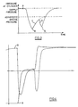
- Figure 3 and plot 8 on Figure 4 represent the hydraulic pressure supplied to one side of the cylinder 1 following the activation of one of the valves 3 and shutting down of the other valve 3 to effect a gear change. Going from left to right on the time axis of Figure 3, at the start the supply pressure is available to the cylinder, that is to say the highest pressure available from the hydraulic pressure source which is used in the system. This relatively high pressure allows the actuator cylinder to move the synchromesh mechanism with a large force to disengage the synchromesh from the previous gear. This enables any resistance associated with separating the meshing of the synchromesh with the previous gear to be overcome easily.
- FIG 4 the position of the synchromesh mechanism is shown as plot 9, with time on the horizontal axis.
- the synchromesh mechanism moves rapidly once it has disengaged the previous gear to the point where the friction element of the synchromesh mechanism engages the corresponding friction element on the gear to be engaged.
- the movement of the synchromesh mechanism is rapid because there is substantially no mechanical resistance offered to the mechanism itself during this stage. Rapid movement is permitted by the hydraulics because of the presence of the accumulator 10 (see Figure 2).
- an accumulator will build up hydraulic fluid under pressure produced, for example, by a mechanical spring.
- the fluid which has built up in the accumulator can be released at high speed.
- the actuator cylinder is thus able to move at high speed once the synchromesh is disengaged from the previous gear, but this period of high speed movement and available hydraulic pressure is limited by the capacity of the accumulator 10.
- the accumulator is in this case dimensioned so that it is almost empty when the friction element of the synchromesh engages the friction element of the gear to be engaged. The accumulator does not empty completely, since this would cause a jerk in the hydraulic circuit which could be transmitted to the driving wheels.
- the pressure available to the actuator is at a minimum following emptying of the accumulator.
- the maximum available pressure which can be attained at the cylinder is determined by the difference in the pressure drop across resistance R 2A or R 2B as appropriate and the pressure drop across R 1 .
- the rate at which the available pressure at the cylinder can increase is also determined by the characteristics of R 1 and R 2A or R 2B as appropriate.
- stage C the accumulator 10 will gradually fill up.
- stage C the end of stage C is determined by the friction elements of the synchromesh and the gear to be engaged matching their speed.
- the positive engagement elements of the synchromesh and the positive engagement elements of the gear to be engaged are free to interlock to achieve full engagement of the next gear.
- the synchromesh will again tend to move rapidly to a position where the positive engaging elements of the synchromesh and the gear to be engaged are fully interlocked.
- point E is reached and the pressure available at the hydraulic actuator cylinder increases again to the supply pressure so that the stationary synchromesh is engaged with the new gear with the maximum possible force.
- the simplified system can, however, be sensitive to low temperatures and consequent increased viscosity of the hydraulic fluid. Increased fluid viscosity will, in general terms, cause the whole system to function more slowly which can cause the engagement of the synchromesh to be too gradual. Added to this, the pressure drop across the restriction R 1 will increase, thus reducing the available pressure at the hydraulic actuator, making its movement even slower. Ideally, the available pressure at the actuator should increase when the temperature drops, to compensate for the general slowing effects of the increased fluid viscosity.
- variable restrictions could be provided which could be linked to the electronic pre-select control, for example.
- different restrictions could be provided in parallel, for example, at R 1 and the path of the hydraulic fluid could be selected to go through one or the other restriction depending on the tractor speed. This would necessitate an electronically controlled valve between the restrictions R 1 and the hydraulic supply.
Landscapes
- Engineering & Computer Science (AREA)
- General Engineering & Computer Science (AREA)
- Mechanical Engineering (AREA)
- Gear-Shifting Mechanisms (AREA)
- Control Of Transmission Device (AREA)
Applications Claiming Priority (2)
| Application Number | Priority Date | Filing Date | Title |
|---|---|---|---|
| GB9512838 | 1995-06-23 | ||
| GBGB9512838.5A GB9512838D0 (en) | 1995-06-23 | 1995-06-23 | Synchromesh control apparatus and method |
Publications (2)
| Publication Number | Publication Date |
|---|---|
| EP0750140A2 true EP0750140A2 (de) | 1996-12-27 |
| EP0750140A3 EP0750140A3 (de) | 1997-12-29 |
Family
ID=10776578
Family Applications (1)
| Application Number | Title | Priority Date | Filing Date |
|---|---|---|---|
| EP96304500A Withdrawn EP0750140A3 (de) | 1995-06-23 | 1996-06-17 | Gangschalt-Steuerungssystem |
Country Status (3)
| Country | Link |
|---|---|
| US (1) | US5697251A (de) |
| EP (1) | EP0750140A3 (de) |
| GB (2) | GB9512838D0 (de) |
Cited By (9)
| Publication number | Priority date | Publication date | Assignee | Title |
|---|---|---|---|---|
| DE19756638A1 (de) * | 1997-12-19 | 1999-06-24 | Zahnradfabrik Friedrichshafen | Schalteinrichtung |
| DE19756637A1 (de) * | 1997-12-19 | 1999-06-24 | Zahnradfabrik Friedrichshafen | Schalteinrichtung |
| EP0947371A3 (de) * | 1998-04-01 | 2000-03-01 | Eaton Corporation | Adaptive Schaltkraftsteuerung eines Stellglieds für ein Splittergetriebe |
| EP1055847A3 (de) * | 1999-05-25 | 2002-12-04 | AISIN AI Co., Ltd. | Schalteinrichtung für Getriebe |
| FR2859007A1 (fr) * | 2000-10-20 | 2005-02-25 | Luk Lamellen & Kupplungsbau | Vehicule a moteur avec boite de vitesses ainsi que procede pour utiliser un vehicule a moteur |
| FR2903460A1 (fr) * | 2006-07-04 | 2008-01-11 | Peugeot Citroen Automobiles Sa | Actionneur hydraulique ameliore pour boite de vitesses d'un vehicule automobile |
| EP1659318A3 (de) * | 2004-11-23 | 2008-08-06 | Zf Friedrichshafen Ag | Schalteinheit für ein Automatgetriebe |
| DE102009002205A1 (de) * | 2009-04-06 | 2010-10-14 | Zf Friedrichshafen Ag | Verfahren zum Betreiben eines Getriebes mit mindestens einem formschlüssigen Schaltelement |
| WO2012160285A1 (fr) * | 2011-05-25 | 2012-11-29 | Peugeot Citroen Automobiles Sa | Dispositif de commande hydraulique d'une boite de vitesses, procede et boîte de vitesses associes |
Families Citing this family (8)
| Publication number | Priority date | Publication date | Assignee | Title |
|---|---|---|---|---|
| NL9401692A (nl) * | 1994-10-13 | 1996-05-01 | Applied Power Inc | Hydraulische bedieningsinrichting en versnellingsbak voorzien van een dergelijke bedieningsinrichting. |
| EP0782675B1 (de) * | 1995-07-26 | 2001-10-24 | Luk Leamington Limited | Gangschaltvorrichtung |
| GB9524073D0 (en) * | 1995-11-24 | 1996-01-24 | Prodrive Eng Ltd | Gear change mechanism |
| SE509819C2 (sv) | 1997-06-27 | 1999-03-08 | Scandmec Ab | Manöveranordning |
| SE509539C2 (sv) * | 1997-06-27 | 1999-02-08 | Scandmec Ab | Manöveranordning |
| DE19931400C2 (de) * | 1999-07-07 | 2001-07-05 | Getrag Getriebe Zahnrad | Hydraulischer Getriebeaktuator und Verfahren zum Angleichen der Drehzahlen von zwei drehenden Elementen |
| GB0025847D0 (en) * | 2000-10-21 | 2000-12-06 | Luk Lamellen & Kupplungsbau | Hydraulic actuation systems |
| CN107882807B (zh) * | 2017-10-25 | 2024-06-11 | 中国第一汽车股份有限公司 | 一种同步器换档气缸及其控制方法 |
Family Cites Families (15)
| Publication number | Priority date | Publication date | Assignee | Title |
|---|---|---|---|---|
| GB1020405A (de) * | ||||
| US3078673A (en) * | 1960-05-27 | 1963-02-26 | Deere & Co | Hydraulic control system for transmission and the like |
| DE1286349B (de) * | 1966-11-22 | 1969-01-02 | Hengstler Hydraulik | Hydraulische Steuereinrichtung zum Beaufschlagen von Kupplungen fuer die Schaltung einzelner Getriebestufen |
| US3596742A (en) * | 1969-11-14 | 1971-08-03 | Metal Bellows Co | Clutch and brake fluidic control system therefor |
| US3674121A (en) * | 1970-09-21 | 1972-07-04 | Gen Motors Corp | Engagement control of friction drives |
| DE2136960B2 (de) * | 1971-07-23 | 1978-07-13 | Ardie-Werk Gmbh, 8500 Nuernberg | Vorrichtung zum Schalten von Zahnradwechselgetrieben insbesondere für Kraftfahrzeuge |
| FR2233893A5 (de) * | 1973-06-18 | 1975-01-10 | Berliet Automobiles | |
| SU974353A1 (ru) * | 1981-05-04 | 1982-11-15 | Дизельный завод "Двигатель революции" | Регул тор в зкости жидкости |
| JPS58184323A (ja) * | 1982-04-23 | 1983-10-27 | Toyota Motor Corp | 歯車変速装置に於ける同期装置の駆動装置 |
| US4560044A (en) * | 1982-06-29 | 1985-12-24 | Kabushiki Kaisha Daikin Seisakusho | Hydraulic pressure modulation device |
| US4555959A (en) * | 1983-05-09 | 1985-12-03 | Eaton Corporation | Shift control system |
| US4653352A (en) * | 1984-02-20 | 1987-03-31 | Aisin Seiki Kabushiki Kaisha | Automatic transmission system for automobiles having hydraulic and electronic control systems |
| SE459760B (sv) * | 1987-11-02 | 1989-07-31 | Volvo Ab | Reglersystem foer en stegvaexlad automatvaexellaada |
| US5092187A (en) * | 1990-11-08 | 1992-03-03 | Rockwell International Corporation | Auxiliary transmission shift control system |
| FR2670265B3 (fr) * | 1990-12-07 | 1992-12-31 | Valeo | Dispositif de commande motorise de changement de rapports de transmission pour boite de vitesses, en particulier pour vehicules automobiles. |
-
1995
- 1995-06-23 GB GBGB9512838.5A patent/GB9512838D0/en active Pending
-
1996
- 1996-06-07 GB GB9611880A patent/GB2302573B/en not_active Expired - Lifetime
- 1996-06-17 EP EP96304500A patent/EP0750140A3/de not_active Withdrawn
- 1996-06-20 US US08/666,977 patent/US5697251A/en not_active Expired - Lifetime
Cited By (13)
| Publication number | Priority date | Publication date | Assignee | Title |
|---|---|---|---|---|
| DE19756637A1 (de) * | 1997-12-19 | 1999-06-24 | Zahnradfabrik Friedrichshafen | Schalteinrichtung |
| US6301984B1 (en) | 1997-12-19 | 2001-10-16 | Zf Friedrichshafen Ag | Gear shifting device |
| DE19756638A1 (de) * | 1997-12-19 | 1999-06-24 | Zahnradfabrik Friedrichshafen | Schalteinrichtung |
| EP0947371A3 (de) * | 1998-04-01 | 2000-03-01 | Eaton Corporation | Adaptive Schaltkraftsteuerung eines Stellglieds für ein Splittergetriebe |
| EP1055847A3 (de) * | 1999-05-25 | 2002-12-04 | AISIN AI Co., Ltd. | Schalteinrichtung für Getriebe |
| FR2859007A1 (fr) * | 2000-10-20 | 2005-02-25 | Luk Lamellen & Kupplungsbau | Vehicule a moteur avec boite de vitesses ainsi que procede pour utiliser un vehicule a moteur |
| EP1659318A3 (de) * | 2004-11-23 | 2008-08-06 | Zf Friedrichshafen Ag | Schalteinheit für ein Automatgetriebe |
| FR2903460A1 (fr) * | 2006-07-04 | 2008-01-11 | Peugeot Citroen Automobiles Sa | Actionneur hydraulique ameliore pour boite de vitesses d'un vehicule automobile |
| EP1882859A1 (de) * | 2006-07-04 | 2008-01-30 | Peugeot Citroën Automobiles Sa | Verbesserte hydraulische Betätigungsvorrichtung für ein Schaltgetriebe eines Kraftfahrzeuges |
| DE102009002205A1 (de) * | 2009-04-06 | 2010-10-14 | Zf Friedrichshafen Ag | Verfahren zum Betreiben eines Getriebes mit mindestens einem formschlüssigen Schaltelement |
| US8483918B2 (en) | 2009-04-06 | 2013-07-09 | Zf Friedrichshafen Ag | Method for operating a transmission with at least one positive-locking shifting element |
| WO2012160285A1 (fr) * | 2011-05-25 | 2012-11-29 | Peugeot Citroen Automobiles Sa | Dispositif de commande hydraulique d'une boite de vitesses, procede et boîte de vitesses associes |
| FR2975743A1 (fr) * | 2011-05-25 | 2012-11-30 | Peugeot Citroen Automobiles Sa | Dispositif de commande hydraulique d'une boite de vitesses, procede et boite de vitesses associes |
Also Published As
| Publication number | Publication date |
|---|---|
| EP0750140A3 (de) | 1997-12-29 |
| GB9512838D0 (en) | 1995-08-23 |
| GB2302573B (en) | 1999-06-16 |
| GB9611880D0 (en) | 1996-08-07 |
| GB2302573A (en) | 1997-01-22 |
| US5697251A (en) | 1997-12-16 |
Similar Documents
| Publication | Publication Date | Title |
|---|---|---|
| US5697251A (en) | Gearshift control system | |
| US4497222A (en) | Clutch control in a multiple clutch type gear transmission for automobile | |
| CN1101529C (zh) | 三位置致动器活塞装置及采用这种装置的致动器系统 | |
| US4519484A (en) | Multiple clutch transmission having gear control device | |
| US5875680A (en) | Automatic forward/reverse gear change system having a main clutch disengaged and main vehicle brake engaged during a shuttle shift | |
| JPH11311325A (ja) | 自動変速装置の制御方法および制御装置 | |
| GB1249500A (en) | Change gear transmission having brake means to facilitate shift and hydraulic control mechanism therefor | |
| EP0577174B1 (de) | Einrichtung zur Kraftübertragung | |
| US5918509A (en) | Powershift reversing transmission | |
| US4187739A (en) | Hydrostatic torque converter having a stepped transmission | |
| EP0330410A2 (de) | Hydraulische Steuervorrichtung für automatische Getriebe | |
| US5680794A (en) | Hydraulic control system for a transmission | |
| JPH07208595A (ja) | 電子シフト装置 | |
| JPS631842A (ja) | 複合クラツチ式多段歯車変速機の制御装置 | |
| JPH09269065A (ja) | 自動変速機の変速制御油圧回路 | |
| JPS631843A (ja) | 複合クラツチ式多段歯車変速機の制御装置 | |
| JPS61136044A (ja) | 油圧操作式ギヤ変速装置の油圧クラツチ作動方法 | |
| JPS6283227A (ja) | 油圧操作式ギヤ変速装置の油圧クラツチ作動方法 | |
| JPH0366976A (ja) | 自動変速機の油圧制御装置 | |
| SU1643213A1 (ru) | Система автоматического переключени передач транспортного средства | |
| JPH02138563A (ja) | 変速機の変速制御方法 | |
| JPH0440577B2 (de) | ||
| JPH0514821B2 (de) | ||
| JPH03213766A (ja) | 自動変速機の変速制御装置 | |
| JPS6152453A (ja) | 車両用自動変速機 |
Legal Events
| Date | Code | Title | Description |
|---|---|---|---|
| PUAI | Public reference made under article 153(3) epc to a published international application that has entered the european phase |
Free format text: ORIGINAL CODE: 0009012 |
|
| AK | Designated contracting states |
Kind code of ref document: A2 Designated state(s): DE FR GB IT |
|
| PUAL | Search report despatched |
Free format text: ORIGINAL CODE: 0009013 |
|
| AK | Designated contracting states |
Kind code of ref document: A3 Designated state(s): DE FR GB IT |
|
| 17P | Request for examination filed |
Effective date: 19980622 |
|
| 17Q | First examination report despatched |
Effective date: 19991025 |
|
| STAA | Information on the status of an ep patent application or granted ep patent |
Free format text: STATUS: THE APPLICATION IS DEEMED TO BE WITHDRAWN |
|
| 18D | Application deemed to be withdrawn |
Effective date: 20000307 |