EP0750972A1 - Machine pour découper des plaquettes d'un lingot avec dispositif intégré de meulage - Google Patents
Machine pour découper des plaquettes d'un lingot avec dispositif intégré de meulage Download PDFInfo
- Publication number
- EP0750972A1 EP0750972A1 EP96304738A EP96304738A EP0750972A1 EP 0750972 A1 EP0750972 A1 EP 0750972A1 EP 96304738 A EP96304738 A EP 96304738A EP 96304738 A EP96304738 A EP 96304738A EP 0750972 A1 EP0750972 A1 EP 0750972A1
- Authority
- EP
- European Patent Office
- Prior art keywords
- spindle
- grinding wheel
- ingot
- stock
- blade
- Prior art date
- Legal status (The legal status is an assumption and is not a legal conclusion. Google has not performed a legal analysis and makes no representation as to the accuracy of the status listed.)
- Granted
Links
- 235000012431 wafers Nutrition 0.000 description 14
- 238000004519 manufacturing process Methods 0.000 description 4
- 239000004065 semiconductor Substances 0.000 description 2
- 239000000463 material Substances 0.000 description 1
- 238000000034 method Methods 0.000 description 1
- 229910052710 silicon Inorganic materials 0.000 description 1
- 239000010703 silicon Substances 0.000 description 1
- 239000010802 sludge Substances 0.000 description 1
Images


Classifications
-
- B—PERFORMING OPERATIONS; TRANSPORTING
- B24—GRINDING; POLISHING
- B24B—MACHINES, DEVICES, OR PROCESSES FOR GRINDING OR POLISHING; DRESSING OR CONDITIONING OF ABRADING SURFACES; FEEDING OF GRINDING, POLISHING, OR LAPPING AGENTS
- B24B7/00—Machines or devices designed for grinding plane surfaces on work, including polishing plane glass surfaces; Accessories therefor
-
- B—PERFORMING OPERATIONS; TRANSPORTING
- B28—WORKING CEMENT, CLAY, OR STONE
- B28D—WORKING STONE OR STONE-LIKE MATERIALS
- B28D1/00—Working stone or stone-like materials, e.g. brick, concrete or glass, not provided for elsewhere; Machines, devices, tools therefor
- B28D1/003—Multipurpose machines; Equipment therefor
-
- B—PERFORMING OPERATIONS; TRANSPORTING
- B24—GRINDING; POLISHING
- B24B—MACHINES, DEVICES, OR PROCESSES FOR GRINDING OR POLISHING; DRESSING OR CONDITIONING OF ABRADING SURFACES; FEEDING OF GRINDING, POLISHING, OR LAPPING AGENTS
- B24B7/00—Machines or devices designed for grinding plane surfaces on work, including polishing plane glass surfaces; Accessories therefor
- B24B7/20—Machines or devices designed for grinding plane surfaces on work, including polishing plane glass surfaces; Accessories therefor characterised by a special design with respect to properties of the material of non-metallic articles to be ground
- B24B7/22—Machines or devices designed for grinding plane surfaces on work, including polishing plane glass surfaces; Accessories therefor characterised by a special design with respect to properties of the material of non-metallic articles to be ground for grinding inorganic material, e.g. stone, ceramics, porcelain
- B24B7/228—Machines or devices designed for grinding plane surfaces on work, including polishing plane glass surfaces; Accessories therefor characterised by a special design with respect to properties of the material of non-metallic articles to be ground for grinding inorganic material, e.g. stone, ceramics, porcelain for grinding thin, brittle parts, e.g. semiconductors, wafers
-
- B—PERFORMING OPERATIONS; TRANSPORTING
- B26—HAND CUTTING TOOLS; CUTTING; SEVERING
- B26D—CUTTING; DETAILS COMMON TO MACHINES FOR PERFORATING, PUNCHING, CUTTING-OUT, STAMPING-OUT OR SEVERING
- B26D1/00—Cutting through work characterised by the nature or movement of the cutting member or particular materials not otherwise provided for; Apparatus or machines therefor; Cutting members therefor
-
- B—PERFORMING OPERATIONS; TRANSPORTING
- B28—WORKING CEMENT, CLAY, OR STONE
- B28D—WORKING STONE OR STONE-LIKE MATERIALS
- B28D5/00—Fine working of gems, jewels, crystals, e.g. of semiconductor material; apparatus or devices therefor
- B28D5/02—Fine working of gems, jewels, crystals, e.g. of semiconductor material; apparatus or devices therefor by rotary tools, e.g. drills
- B28D5/022—Fine working of gems, jewels, crystals, e.g. of semiconductor material; apparatus or devices therefor by rotary tools, e.g. drills by cutting with discs or wheels
- B28D5/028—Fine working of gems, jewels, crystals, e.g. of semiconductor material; apparatus or devices therefor by rotary tools, e.g. drills by cutting with discs or wheels with a ring blade having an inside cutting edge
Definitions
- the present invention relates to an inner diameter saw slicing machine with built-in grinder.
- Such a machine is used to manufacture a wafer of a predetermined thickness by moving an ingot, such as one made of silicon which is a material for a semiconductor element, relative to a rotary inner diameter saw blade.
- the blade rigidity in the axial direction is low, so slice resistance increases due to kerf wear, and sludge occurs between the ingot and the blade as slicing proceeds. Therefore, the blade kerf is easily displaced from its original position, and as a result both sides of the sliced wafer may be bowed in many cases.
- our Japanese Patent Publication No. 2-12729 discloses a slicing machine incorporating a grinding wheel, which machine slices an ingot while simultaneously grinding an ingot cutting face.
- FIG. 5 shows an example of a known vertical inner diameter saw grinding machine with built-in grinder.
- a table 4 is supported by a table guide 2, which is provided on a top of a base 1, in such a manner as to move freely in directions a and b.
- a column 5 is attached to the table 4.
- a tension head 13 is supported by a rotation mechanism.
- a blade 14 is tensioned by a top ring 15 and is attached to the tension head 13.
- An inner diameter saw 14a is formed at the inner diameter of the blade 14.
- a hollow portion is formed in the main spindle which rotatably supports the blade 14.
- a grinding wheel 28 is secured to a wheel spindle, which extends through the hollow portion, in such a manner to move vertically and to rotate.
- a cup-shaped wheel face 28a is formed on the top of the grinding wheel 28.
- the grinding wheel 28a is positioned down from the inner diameter saw 14a by the intended thickness of the wafer.
- the support mechanism for the grinding wheel 28 in this example is disclosed in aforementioned Japanese Patent Applications Laid-open Nos. 1-210313 and 4-71688.
- An inner cover 18 is fixed at the base 1 in the tension head 13.
- the blade 14 In operation of this machine the blade 14 is rotated at a high speed.
- An ingot W is moved by the table 4 in a direction Xa from a substantially central position of the blade 14, with a cutting face of the ingot W positioned down from the inner diameter saw 14a by the intended thickness of the wafer, so that the ingot is sliced.
- the ingot is ground by the wheel face 28a of the grinding wheel 28 prior to being sliced by the inner diameter saw 14a. That is, the ingot is sliced while the end face of the ingot is being ground.
- the grinding wheel 28 moves in a downward direction so as not to interfere with a wafer collection saucer, which holds the wafer in a collection mechanism.
- the rotational center of the grinding wheel 28 corresponds to that of the inner diameter saw 14a.
- the relationship between the diameter of the inner diameter saw 14a, the diameter of the grinding wheel 28, and the initial position of the ingot W is determined in the following manner.
- Fig. 4(a) is a plan view
- Fig. 4(b) is a section view
- the diameter C of the inner diameter saw 14a for the collection saucer and its support spindle to pass through is determined by the diameter A of the ingot W and the length B in Fig. 4(a) in the direction of a slice base, so that a wafer which has been sliced can be collected.
- a value ⁇ which is larger than a width t in the radial direction of the grinding wheel 28 and the wheel face 28a, is set. Then, the initial position of the ingot W is determined so that a slicing start point Wa can be positioned inwardly from an outer diameter face of the grinding wheel 28 by distance ⁇ .
- ⁇ is almost automatically set by the width t in the radial direction of the wheel face 28a of the grinding wheel 28. So, the slicing movement distance Eb is determined by the gap ⁇ in the radial direction between the inner diameter saw 14a and the grinding wheel 28.
- the rotational center of the grinding wheel 28 corresponds to that of the inner diameter saw 14a. This is why the diameter Db of the grinding wheel 28 should be made large in order to reduce the gap ⁇ in the radial direction between the inner diameter saw 14a and the grinding wheel 28.
- the apparatus for rotating the grinding wheel at a high speed becomes more expensive. If the rotational speed of the grinding wheel is made low so as to avoid such use of the expensive apparatus, it is difficult to obtain a satisfactory grinding face. Further, if the diameter Db of the grinding wheel is made large, it is difficult for the wheel face 28a to be accurate.
- an inner diameter saw slicing machine with built-in grinder comprising:
- a spindle stock extends through a hollow portion in a main spindle which supports the said blade for rotation, so as to be movable parallel to the axis of the main spindle.
- a grinding wheel spindle is rotatably supported by the said spindle stock.
- a fixed spindle stock extends through a hollow portion of the main blade spindle.
- An intermediate spindle is rotatably supported by the spindle stock.
- a grinding wheel spindle is provided within the intermediate spindle, movable axially thereof.
- the wheel spindle and the intermediate spindle can be driven in rotation by an outside motor.
- a built-in motor may be provided by, in the first form, using the wheel spindle as a rotor and the spindle stock as a stator, or in the second form using the intermediate spindle as a rotor and the spindle stock as a stator.
- the rotational center of the grinding wheel is displaced in the slice feed direction with respect to the rotational center of the inner diameter saw. Therefore, the opening between the inner diameter saw and the grinding wheel in that direction can be made smaller, even if the diameter of the grinding wheel is not large. As a result, the slicing movement distance of the ingot can be shorter.
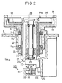
- Fig. 2 illustrates a first embodiment of a grinding wheel support mechanism in an inner diameter saw slicing machine with built-in grinder according to the present invention.
- the mechanism includes a support mechanism for a blade 14.
- a grinding wheel 28 is positioned at a top end when ground.
- a housing 11 is secured to a base 1, and a main spindle 12 is rotatably supported by bearings 11a and 11a, which are mounted in the housing 11.
- a tension head 13 is secured to the top of the main spindle 12.
- a blade 14 is tensioned by a top ring 15, and is attached to the tension head 13.
- a drive pulley 16 is secured to the bottom end of the main spindle 12, and connects to the spindle of a motor (not shown).
- the blade 14 rotates in a substantially horizontal plane, interlocking with the rotation of the main spindle 12.
- An inner cover 18 is secured to the top end of a column 17 mounted on a bracket 21.
- the bracket 21 is secured to the underside of the base 1.
- a slide block 23 is supported by a linear guide 22, which is attached to the bracket 21, so as to be movable vertically.
- a spindle stock 24 stands on the slide block 23, extending through a hollow portion in the main spindle 12. Bearings 24a and 24a are built in the spindle stock 24, and a wheel spindle 26 is rotatably supported by the spindle stock 24. A grinding wheel 28 is secured to a top end of spindle 26.
- a stator 25 is provided in the spindle cradle 24, and a rotor 27 is provided in the wheel spindle 26.
- the stator 25 and the rotor 27 compose a built-in motor.
- a straight drive means 30 is provided below the slide block 23.
- a housing 31 is provided with a worm wheel 32 and a worm 33 for driving the worm wheel 32.
- a screw is formed at a spindle center of the worm wheel 32, and is engaged with a feed screw 34, which is secured to the bottom of the slide block 23.
- the support mechanism for the grinding wheel 28 in the first embodiment is constructed in the described manner.
- the grinding wheel 28 is rotated by the built-in motor, which is composed of the stator 25 and the rotor 27.
- the worm 33 is rotated by a motor (not shown) in the straight drive means 30, so that the worm wheel 32 rotates and the feed screw 34 moves vertically, whereby the whole spindle stock 24 including the rotation mechanism moves vertically.
- Fig. 3 illustrates a second embodiment of a grinding wheel support mechanism.
- the support mechanism for the blade 14 is the same as that of the first embodiment.
- the grinding wheel 28 is positioned at the top end when ground.
- a bracket 41 is secured to the underside of the base 1.
- a spindle stock 42 is attached to the bracket 41, extending through a hollow portion in the main spindle 12.
- Bearings 42a and 42a are mounted in the spindle stock 42, and an intermediate spindle 43 is rotatably supported by the spindle stock 42.
- a drive pulley 45 is secured to the bottom of the intermediate spindle 43, and connects to a spindle of a motor (not shown).
- Spline stocks 43a and 43a are provided in the intermediate spindle 43, and the wheel spindle 44 is supported by the spline stocks 43a and 43a so as to be movable in the direction of the main spindle 12.
- a spline 44a is formed at the outer diameter of the wheel spindle 44.
- the grinding wheel 28 is secured to the top end of the wheel spindle 44.
- a slide block 48 is supported by a linear guide 47, which is attached to a bottom of the bracket 41, so as to be to movable vertically.
- Thrust bearings 48a and 48a are mounted in the slide block 48.
- the top and bottom of a flange 44b, which is formed at the bottom end of the wheel spindle 44, are supported by the thrust bearings 48a and 48a.
- Straight drive means 30, which was explained in the first embodiment, is provided below the slide block 48, the feed screw 34 of the straight drive means 30 being secured to the bottom of the slide block 48.
- the support mechanism for the grinding wheel 28 is constructed in the above described manner.
- the slide block is moved up and down by the straight drive means 30, so that the wheel spindle 44 moves vertically.
- the vertical movement mechanism and the rotation mechanism are independent of each other.
- rotation mechanism and the vertical movement mechanism of the grinding wheel 28 are not limited to the above-described embodiments, and the present invention can be applied in other ways.
- the motor 25, 27 is located between the spindle stock 24 and the wheel spindle 26.
- the motor may be provided outside, as in the second embodiment. Further, in the second embodiment the motor may be located between the spindle stock 42 and the spindle 43.
- the rotational center of the grinding wheel 28 is displaced to the slicing side in the slice feed direction, with respect to the rotational center of the inner diameter saw 14a.
- the grinding wheel 28 can be located close to the inner diameter saw 14a, so that the slicing movement distance Ea of the ingot W can be shorter.
- the diameter Da of the grinding wheel 28 is small, so that its support mechanism can be small and therefore can be low-priced, and the accuracy of the grinding face 28a can be improved.
- the total area of the gap between the inner diameter saw 14a and the grinding wheel 28 (the difference between the area of the circle defined by the inner diameter saw 14a and the area of the grinding wheel 28) is large. As a result, there is less likelihood that the saw 14 will move in the spindle direction due to the wind pressure, etc. caused by the rotation of the grinding wheel 28.
- the present embodiments can provide a low-priced inner diameter saw slicing machine with built-in grinder, wherein the slicing time is short and the accuracy of the grinding face is satisfactory.
Landscapes
- Engineering & Computer Science (AREA)
- Mechanical Engineering (AREA)
- Chemical & Material Sciences (AREA)
- Ceramic Engineering (AREA)
- Inorganic Chemistry (AREA)
- Mining & Mineral Resources (AREA)
- Life Sciences & Earth Sciences (AREA)
- Forests & Forestry (AREA)
- Processing Of Stones Or Stones Resemblance Materials (AREA)
- Mechanical Treatment Of Semiconductor (AREA)
Applications Claiming Priority (3)
| Application Number | Priority Date | Filing Date | Title |
|---|---|---|---|
| JP18671195 | 1995-06-30 | ||
| JP186711/95 | 1995-06-30 | ||
| JP18671195A JP3174484B2 (ja) | 1995-06-30 | 1995-06-30 | 平面研削内周刃切断複合加工機 |
Publications (2)
| Publication Number | Publication Date |
|---|---|
| EP0750972A1 true EP0750972A1 (fr) | 1997-01-02 |
| EP0750972B1 EP0750972B1 (fr) | 2001-09-26 |
Family
ID=16193309
Family Applications (1)
| Application Number | Title | Priority Date | Filing Date |
|---|---|---|---|
| EP96304738A Expired - Lifetime EP0750972B1 (fr) | 1995-06-30 | 1996-06-27 | Machine pour découper des plaquettes d'un lingot avec dispositif intégré de meulage |
Country Status (5)
| Country | Link |
|---|---|
| US (1) | US5836808A (fr) |
| EP (1) | EP0750972B1 (fr) |
| JP (1) | JP3174484B2 (fr) |
| KR (1) | KR100385428B1 (fr) |
| DE (1) | DE69615463T2 (fr) |
Cited By (1)
| Publication number | Priority date | Publication date | Assignee | Title |
|---|---|---|---|---|
| CN102364295A (zh) * | 2011-06-30 | 2012-02-29 | 常州天合光能有限公司 | 一种晶锭边皮厚度的测量方法 |
Families Citing this family (2)
| Publication number | Priority date | Publication date | Assignee | Title |
|---|---|---|---|---|
| US9527147B2 (en) | 2014-05-30 | 2016-12-27 | Simonds International Llc | Saw blade indexing assembly |
| CN107962488A (zh) * | 2016-10-19 | 2018-04-27 | 张云清 | 储尘防火遥控半自动切割机 |
Citations (6)
| Publication number | Priority date | Publication date | Assignee | Title |
|---|---|---|---|---|
| FR2469259A1 (fr) * | 1979-08-08 | 1981-05-22 | Radiotechnique Compelec | Procede d'elaboration de plaquettes de materiaux durs, notamment de silicium et appareil de mise en oeuvre du procede |
| JPS61106207A (ja) * | 1984-10-31 | 1986-05-24 | 株式会社東京精密 | ウエハー製造方法並びに装置 |
| EP0313714A1 (fr) * | 1987-10-29 | 1989-05-03 | Tokyo Seimitsu Co.,Ltd. | Appareil et procédé pour découper une plaquette |
| JPH01115604A (ja) * | 1987-10-29 | 1989-05-08 | Tokyo Seimitsu Co Ltd | ウエハの切断装置 |
| JPH01210313A (ja) * | 1988-02-18 | 1989-08-23 | Tokyo Seimitsu Co Ltd | ウエハの切断装置 |
| JPH0615634A (ja) * | 1992-07-02 | 1994-01-25 | Tokyo Seimitsu Co Ltd | ウエハのスライシング方法 |
Family Cites Families (2)
| Publication number | Priority date | Publication date | Assignee | Title |
|---|---|---|---|---|
| JPH02212729A (ja) * | 1989-02-13 | 1990-08-23 | Koorin Denshi Kk | 圧力センサ |
| JP2577653B2 (ja) * | 1990-07-10 | 1997-02-05 | フジクリーン工業株式会社 | 小規模合併処理浄化槽における排出流量の調整装置 |
-
1995
- 1995-06-30 JP JP18671195A patent/JP3174484B2/ja not_active Expired - Fee Related
-
1996
- 1996-06-20 KR KR1019960022604A patent/KR100385428B1/ko not_active Expired - Fee Related
- 1996-06-21 US US08/667,791 patent/US5836808A/en not_active Expired - Fee Related
- 1996-06-27 EP EP96304738A patent/EP0750972B1/fr not_active Expired - Lifetime
- 1996-06-27 DE DE69615463T patent/DE69615463T2/de not_active Expired - Fee Related
Patent Citations (8)
| Publication number | Priority date | Publication date | Assignee | Title |
|---|---|---|---|---|
| FR2469259A1 (fr) * | 1979-08-08 | 1981-05-22 | Radiotechnique Compelec | Procede d'elaboration de plaquettes de materiaux durs, notamment de silicium et appareil de mise en oeuvre du procede |
| JPS61106207A (ja) * | 1984-10-31 | 1986-05-24 | 株式会社東京精密 | ウエハー製造方法並びに装置 |
| JPH0212729B2 (fr) * | 1984-10-31 | 1990-03-26 | Tokyo Seimitsu Co Ltd | |
| EP0313714A1 (fr) * | 1987-10-29 | 1989-05-03 | Tokyo Seimitsu Co.,Ltd. | Appareil et procédé pour découper une plaquette |
| JPH01115604A (ja) * | 1987-10-29 | 1989-05-08 | Tokyo Seimitsu Co Ltd | ウエハの切断装置 |
| JPH0471688B2 (fr) * | 1987-10-29 | 1992-11-16 | Tokyo Seimitsu Co Ltd | |
| JPH01210313A (ja) * | 1988-02-18 | 1989-08-23 | Tokyo Seimitsu Co Ltd | ウエハの切断装置 |
| JPH0615634A (ja) * | 1992-07-02 | 1994-01-25 | Tokyo Seimitsu Co Ltd | ウエハのスライシング方法 |
Non-Patent Citations (1)
| Title |
|---|
| PATENT ABSTRACTS OF JAPAN vol. 18, no. 217 (M - 1594) 19 April 1994 (1994-04-19) * |
Cited By (2)
| Publication number | Priority date | Publication date | Assignee | Title |
|---|---|---|---|---|
| CN102364295A (zh) * | 2011-06-30 | 2012-02-29 | 常州天合光能有限公司 | 一种晶锭边皮厚度的测量方法 |
| CN102364295B (zh) * | 2011-06-30 | 2013-03-06 | 常州天合光能有限公司 | 一种晶锭边皮厚度的测量方法 |
Also Published As
| Publication number | Publication date |
|---|---|
| KR100385428B1 (ko) | 2003-08-19 |
| US5836808A (en) | 1998-11-17 |
| DE69615463D1 (de) | 2001-10-31 |
| DE69615463T2 (de) | 2002-04-25 |
| JP3174484B2 (ja) | 2001-06-11 |
| EP0750972B1 (fr) | 2001-09-26 |
| KR970000449A (ko) | 1997-01-21 |
| JPH0911227A (ja) | 1997-01-14 |
Similar Documents
| Publication | Publication Date | Title |
|---|---|---|
| EP0313714B1 (fr) | Appareil et procédé pour découper une plaquette | |
| RU2320467C2 (ru) | Способ шлифования снабженной продольным отверстием вращательно-симметричной машинной детали и устройство для его реализации | |
| EP0491051A1 (fr) | Meule a commande numerique pour plaque de verre | |
| EP1193029B1 (fr) | Procédé de meulage des deux faces d'un disque fin | |
| KR20010085505A (ko) | 에이치에프-스핀들을 구비한 그라인딩 휠과 톱날 그라인딩머신 | |
| US5915370A (en) | Saw for segmenting a semiconductor wafer | |
| KR20060044312A (ko) | 베벨기어 톱니선단을 모따기하거나 귀따기하는 베벨기어절삭장치 | |
| EP0750972B1 (fr) | Machine pour découper des plaquettes d'un lingot avec dispositif intégré de meulage | |
| JPH07285024A (ja) | 歯車の製造方法および装置 | |
| JP5441057B2 (ja) | ワイヤソー | |
| US20030056628A1 (en) | Coaxial spindle cutting saw | |
| JPS5850822B2 (ja) | 刃物を研磨する方法と該方法を実施するための研磨機 | |
| JP2011110643A5 (fr) | ||
| JP2020075314A (ja) | ウェーハの面取り加工装置 | |
| CN220196535U (zh) | 自动铣齿机 | |
| US4712535A (en) | Method and apparatus for severing wafers | |
| US6375555B1 (en) | Vane groove grinding apparatus for compressor cylinder | |
| JPH06169013A (ja) | ダイシング装置及びダイシング装置における切削制御方法 | |
| JP2737783B2 (ja) | ウエハの切断装置 | |
| JP3199355B2 (ja) | 内周刃のドレッシング方法 | |
| JP2681582B2 (ja) | シート材のスリット方法およびスリッター装置 | |
| JP2537458B2 (ja) | デュアルコンタリング加工による切粉微細化装置 | |
| US1207143A (en) | Dough-kneading machine. | |
| JP2001025943A (ja) | 円筒状工作物の外周面研削装置および研削方法 | |
| CN116748604A (zh) | 自动铣齿机 |
Legal Events
| Date | Code | Title | Description |
|---|---|---|---|
| PUAI | Public reference made under article 153(3) epc to a published international application that has entered the european phase |
Free format text: ORIGINAL CODE: 0009012 |
|
| AK | Designated contracting states |
Kind code of ref document: A1 Designated state(s): DE GB IT |
|
| 17P | Request for examination filed |
Effective date: 19970207 |
|
| 17Q | First examination report despatched |
Effective date: 19991118 |
|
| GRAG | Despatch of communication of intention to grant |
Free format text: ORIGINAL CODE: EPIDOS AGRA |
|
| GRAG | Despatch of communication of intention to grant |
Free format text: ORIGINAL CODE: EPIDOS AGRA |
|
| GRAH | Despatch of communication of intention to grant a patent |
Free format text: ORIGINAL CODE: EPIDOS IGRA |
|
| GRAH | Despatch of communication of intention to grant a patent |
Free format text: ORIGINAL CODE: EPIDOS IGRA |
|
| GRAA | (expected) grant |
Free format text: ORIGINAL CODE: 0009210 |
|
| AK | Designated contracting states |
Kind code of ref document: B1 Designated state(s): DE GB IT |
|
| REF | Corresponds to: |
Ref document number: 69615463 Country of ref document: DE Date of ref document: 20011031 |
|
| REG | Reference to a national code |
Ref country code: GB Ref legal event code: IF02 |
|
| PLBE | No opposition filed within time limit |
Free format text: ORIGINAL CODE: 0009261 |
|
| STAA | Information on the status of an ep patent application or granted ep patent |
Free format text: STATUS: NO OPPOSITION FILED WITHIN TIME LIMIT |
|
| 26N | No opposition filed | ||
| PGFP | Annual fee paid to national office [announced via postgrant information from national office to epo] |
Ref country code: GB Payment date: 20030624 Year of fee payment: 8 |
|
| PGFP | Annual fee paid to national office [announced via postgrant information from national office to epo] |
Ref country code: DE Payment date: 20030626 Year of fee payment: 8 |
|
| PG25 | Lapsed in a contracting state [announced via postgrant information from national office to epo] |
Ref country code: GB Free format text: LAPSE BECAUSE OF NON-PAYMENT OF DUE FEES Effective date: 20040627 |
|
| PG25 | Lapsed in a contracting state [announced via postgrant information from national office to epo] |
Ref country code: DE Free format text: LAPSE BECAUSE OF NON-PAYMENT OF DUE FEES Effective date: 20050101 |
|
| GBPC | Gb: european patent ceased through non-payment of renewal fee |
Effective date: 20040627 |
|
| PG25 | Lapsed in a contracting state [announced via postgrant information from national office to epo] |
Ref country code: IT Free format text: LAPSE BECAUSE OF NON-PAYMENT OF DUE FEES Effective date: 20050627 |