EP0751531A2 - Vorrichtung zur Messung wenigstens eines physikalischen Parameters innerhalb des Kerns eines nuklearen Reaktors - Google Patents
Vorrichtung zur Messung wenigstens eines physikalischen Parameters innerhalb des Kerns eines nuklearen Reaktors Download PDFInfo
- Publication number
- EP0751531A2 EP0751531A2 EP96401338A EP96401338A EP0751531A2 EP 0751531 A2 EP0751531 A2 EP 0751531A2 EP 96401338 A EP96401338 A EP 96401338A EP 96401338 A EP96401338 A EP 96401338A EP 0751531 A2 EP0751531 A2 EP 0751531A2
- Authority
- EP
- European Patent Office
- Prior art keywords
- sleeve
- measurement
- bore
- measuring
- conduit
- Prior art date
- Legal status (The legal status is an assumption and is not a legal conclusion. Google has not performed a legal analysis and makes no representation as to the accuracy of the status listed.)
- Granted
Links
- 239000000523 sample Substances 0.000 claims abstract description 29
- 238000007789 sealing Methods 0.000 claims abstract description 21
- 238000005259 measurement Methods 0.000 claims description 83
- 125000006850 spacer group Chemical group 0.000 claims description 8
- 238000006073 displacement reaction Methods 0.000 claims description 7
- 238000004891 communication Methods 0.000 claims description 3
- OKTJSMMVPCPJKN-UHFFFAOYSA-N Carbon Chemical compound [C] OKTJSMMVPCPJKN-UHFFFAOYSA-N 0.000 claims description 2
- 229910002804 graphite Inorganic materials 0.000 claims description 2
- 239000010439 graphite Substances 0.000 claims description 2
- 229910001220 stainless steel Inorganic materials 0.000 claims description 2
- 239000010935 stainless steel Substances 0.000 claims description 2
- 230000004907 flux Effects 0.000 abstract description 4
- 230000008878 coupling Effects 0.000 abstract 3
- 238000010168 coupling process Methods 0.000 abstract 3
- 238000005859 coupling reaction Methods 0.000 abstract 3
- 238000012544 monitoring process Methods 0.000 abstract 1
- 239000004606 Fillers/Extenders Substances 0.000 description 9
- XLYOFNOQVPJJNP-UHFFFAOYSA-N water Substances O XLYOFNOQVPJJNP-UHFFFAOYSA-N 0.000 description 9
- 238000000034 method Methods 0.000 description 8
- 230000008439 repair process Effects 0.000 description 6
- 238000011144 upstream manufacturing Methods 0.000 description 6
- 230000000712 assembly Effects 0.000 description 5
- 238000000429 assembly Methods 0.000 description 5
- 239000000498 cooling water Substances 0.000 description 4
- 238000001816 cooling Methods 0.000 description 3
- 238000000605 extraction Methods 0.000 description 3
- 239000000446 fuel Substances 0.000 description 3
- 238000003754 machining Methods 0.000 description 3
- 230000008569 process Effects 0.000 description 3
- 238000000926 separation method Methods 0.000 description 3
- 230000008859 change Effects 0.000 description 2
- 230000000694 effects Effects 0.000 description 2
- 230000000149 penetrating effect Effects 0.000 description 2
- 238000011084 recovery Methods 0.000 description 2
- 238000003466 welding Methods 0.000 description 2
- 230000004913 activation Effects 0.000 description 1
- 239000002826 coolant Substances 0.000 description 1
- 238000005520 cutting process Methods 0.000 description 1
- 238000009826 distribution Methods 0.000 description 1
- 238000005553 drilling Methods 0.000 description 1
- 230000004992 fission Effects 0.000 description 1
- 239000012530 fluid Substances 0.000 description 1
- 230000001681 protective effect Effects 0.000 description 1
- 230000000284 resting effect Effects 0.000 description 1
Images


Classifications
-
- G—PHYSICS
- G21—NUCLEAR PHYSICS; NUCLEAR ENGINEERING
- G21C—NUCLEAR REACTORS
- G21C17/00—Monitoring; Testing ; Maintaining
- G21C17/10—Structural combination of fuel element, control rod, reactor core, or moderator structure with sensitive instruments, e.g. for measuring radioactivity, strain
-
- Y—GENERAL TAGGING OF NEW TECHNOLOGICAL DEVELOPMENTS; GENERAL TAGGING OF CROSS-SECTIONAL TECHNOLOGIES SPANNING OVER SEVERAL SECTIONS OF THE IPC; TECHNICAL SUBJECTS COVERED BY FORMER USPC CROSS-REFERENCE ART COLLECTIONS [XRACs] AND DIGESTS
- Y02—TECHNOLOGIES OR APPLICATIONS FOR MITIGATION OR ADAPTATION AGAINST CLIMATE CHANGE
- Y02E—REDUCTION OF GREENHOUSE GAS [GHG] EMISSIONS, RELATED TO ENERGY GENERATION, TRANSMISSION OR DISTRIBUTION
- Y02E30/00—Energy generation of nuclear origin
- Y02E30/30—Nuclear fission reactors
Definitions
- the invention relates to a device for measuring at least one physical parameter, such as temperature or neutron flux, inside the core of a nuclear reactor and more particularly of a nuclear reactor cooled by water. under pressure.
- Pressurized water nuclear reactors comprise a core formed of vertically arranged prismatic assemblies resting on a support plate, inside the nuclear reactor vessel.
- thermowells are introduced according to a predetermined distribution in certain assemblies of the core, after passage inside an instrumentation guide duct.
- Each of the instrumentation guide conduits comprises a guide tube connecting a measurement room to the bottom of the nuclear reactor vessel, via a bottom crossing sleeve and a vertical channel passing through the lower internal equipment of the reactor. , in alignment with the vertical guide tube of the fuel assembly into which the thermowell is introduced.
- flow measurements can be made along the entire height of the core.
- thermowell a set of sensors constituted by neutron flux detectors or sensors temperature measuring devices which are fixed in spaced apart arrangements along the length of a measuring cable which is inserted inside the thermowell or of a closed sheath similar to a thermowell.
- the flow or temperature detectors, integral with the measurement cable, are thus placed inside the core, in fixed arrangements stepped according to the height of the core.
- the guide conduits which are connected to the bottom of the tank are in communication with the internal volume of the tank which contains cooling water under pressure and at very high temperature and allow the passage of a measurement pipe of which a part penetrates in the heart of the nuclear reactor.
- the measurement conduits must be able to be moved inside the guide conduits, for example to carry out their extraction from the assemblies of the core or their complete extraction from the guide conduits, in the event that a replacement is necessary.
- Pressurized water for cooling the reactor fills the annular space formed between the interior surface of the guide duct and the exterior surface of the thermowell which is therefore subjected to a fluid at very high temperature and very high pressure.
- the open end of the thermowell, opposite the end engaged inside the core of the nuclear reactor must be accessible from the measurement room of the nuclear reactor.
- the probes are engaged inside the thermowell and moved from the measurement room.
- the measurement probes are fixed to a flexible element on which a pull or a push is applied to move them.
- the measurement signals are collected and processed inside the measurement room.
- a displacement and measurement assembly is used making it possible to carry out a controlled displacement of the mobile probes and recovery and processing of the measurement signals. If fixed probes are used, these probes are connected to a measurement cable which must be connected inside the measurement room to a signal processing assembly.
- the guide duct includes a sealed passage of the thimble, on an end part arranged in the measurement room.
- This sealed glove passage device generally called a nozzle, includes sets of seals making it possible to seal around the surface of the end of the glove finger as it exits the guide duct.
- the spout has an upstream end through which the end of the thimble penetrates and a downstream end to which is generally connected a thimble extension making it possible to ensure the junction between the spout and the movement and recovery assembly of probe measurement signals.
- the end of the measuring pipe or thimble is fixed by welding to a part of the extension by means of which the connection is made between the thimble and the nozzle.
- the spout includes a nut intended to come to bear on a shoulder of the extension to ensure its fixing on the spout.
- thermowells When it is desired to move the thermowells inside the guide conduits, for example to extract the thermowells from the fuel assemblies before reloading, the nut of the nozzle is removed and a pull is exerted on the extender of the thermowell.
- the thermowell can be replaced inside the guide duct by pushing on the extension.
- thermowell In the case where one wishes to carry out a repair of a part of the guide duct, for example a repair or a replacement of the nozzle fixed on the guide duct, it may be necessary to completely remove the thimble from the guide duct.
- the extraction of the thermowell inside the measurement room of the nuclear reactor is a delicate operation since the thermowell has a very long length and an activation which can be strong, after a certain time of stay in the nuclear reactor in operation. It is generally necessary to eliminate the thermowell by cutting inside the measuring room and storing the sections of the thermowell in a container. Prior to this thimble removal operation, it is necessary to separate the thimble from its extension by machining the connecting weld between the thimble and the extension.
- thermowell and plugging To carry out these different operations of moving the thermowell and plugging, a tool is used which can be manipulated from the measurement room of the nuclear reactor.
- thermowell For the implementation of the method, however, it remains necessary to separate the thermowell from its extender or from a connecting piece to the extender by a machining operation which has drawbacks due to the fact that shavings are produced. machining in the nuclear reactor measurement room. In addition, this operation can be relatively long and delicate; when putting the thimble back into service, it is necessary to re-weld an extender at the end of the thimble.
- thermowell There is also known a process described in FR-A-2,693,310 in the name of the company FRAMATOME which makes it possible to slightly modify the service position of a thermowell inside a guide duct for moving the zones preferential wear of the thermowell inside the nuclear reactor, along the length of the thermowell. This increases the life of the thermowell.
- a device for modifying the axial position of the thermowell inside the guide duct which comprises a thermowell extension of a particular shape having a threaded bore allowing receive a threaded piece attached to the end of the thermowell, which is screwed to inside the extender.
- extensions having a tapped opening of suitable length and optionally, one or more spacers engaged around the thimble, the position of the thimble can be varied inside the guide duct.
- Such a device requires the presence of a threaded element added and welded to the end of the thimble.
- thermowells In the case of the use of sensors in a fixed position inside the core of the nuclear reactor, these sensors being fixed on a cylindrical element such as a cable engaged in a sheath similar to a thermowell, the passage nozzles of thermowells according to the prior art do not allow the connection of the measurement cable to a measurement assembly inside the nuclear reactor room to be ensured in a simple manner as well as perfect sealing around the cylindrical element making it possible to avoid any entry of cooling water from the nuclear reactor into the measurement room, in the event of a crack in the thermowell.
- the object of the invention is to propose a device for measuring at least one physical parameter inside the core of a nuclear reactor comprising a measurement conduit of elongated shape, a conduit for guiding the measurement conduit between a measurement room and the core of the nuclear reactor placed inside a vessel, a means for leaktight passage of the measurement pipe at one end of the guide pipe located in the measurement room, a measurement processing assembly and a cylindrical element extending the measurement conduit arranged between the sealed passage means of the measurement conduit and the measurement processing assembly, characterized in that it further comprises an element for connecting an end portion of the conduit measuring element with an extension element comprising a body constituted by a tubular sleeve comprising along its axis, a first receiving bore of the end portion of the measurement conduit having a smooth cylindrical surface, extending between a first axial end of the sleeve and a shoulder inside the sleeve, a second receiving bore from the cylindrical element extending to the second axial end of the sleeve, a first removable means for fixing and sealing passage
- Figure 1 is a schematic elevational view in partial section of the vessel of a pressurized water nuclear reactor and of a device for measuring physical parameters inside the core of the nuclear reactor.
- Figure 2 is a side elevational view of part of the elements of a guide duct of the measuring device placed inside the measuring room.
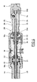
- Figure 3 is a sectional view on a larger scale of a portion of the guide duct shown in Figure 2 ensuring the sealed passage of a measurement conduit and the connection of an extension according to the prior art.
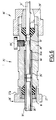
- Figure 4 is a sectional view similar to the view of Figure 3 of a portion of a guide duct of a measuring device according to the invention.
- Figure 5 is a sectional view of a connecting and fixing element of a measuring device according to the invention and according to a first embodiment.
- Figure 6 is a sectional view of a connecting and fixing element of a measuring device according to the invention and according to a second embodiment.
- a measurement room 3 surrounded by concrete walls is arranged laterally with respect to the tank well 2.
- One of the side walls 4 of room 3 separates this room from the tank well 2.
- Instrumentation guide conduits such as 5 are connected at one of their ends to a vertical cuff 6 crossing the bottom of the tank 1 and provide the connection between the bottom of the tank 1 and the instrument room 3 into which each of the measurement conduits 5 penetrates in a horizontal direction.
- On the horizontal extension of each of the guide conduits 5 inside the room 3 are arranged, successively, from the through wall 4 of the room 3, a manual valve 7, a nozzle 8 for tight passage of a finger of glove introduced into the guide duct 5 and an automatic valve 9.
- the nozzle 8 ensures the sealed passage of a thimble which is connected to the outlet of the nozzle 8, to a thimble extension 12 ensuring the passage of a cylindrical element 11 between the nozzle 8 and a measuring assembly and displacement 10.
- the cylindrical element 11 has a tubular shape which allows the passage of the mobile probes fixed to the end of a teleflex cable inside the thimble. extending along the length of the guide duct 5.
- the measuring assembly 10 comprises means for moving the probes inside the guide tubes and means for collecting the measurement signals from each of the probes.
- the cylindrical element 11 is a measuring cable on which are fixed the probes which are introduced in a fixed position inside the thermowell placed in the core of the nuclear reactor.
- FIG. 2 the elements arranged on the guide duct 5 are shown in greater detail inside the measurement room 3.
- the nozzle 8 which is shown in FIGS. 2 and 3 allowing the sealed passage of a thermowell 14 comprises a body of threaded nozzle at its ends on which nuts 8a and 8b are engaged.
- the nut 8a makes it possible to connect a connecting piece of the guide duct 5 to the body of the nozzle 8, at the outlet of the manual valve 7.
- a set of seals 13 is interposed between the connecting piece of the duct 5 and the body of the nozzle 8.
- a sealing gasket 15 is arranged around the thimble 14 to allow its leaktight passage inside the body of the nozzle 8.
- the second nut 8b of the nozzle 8 makes it possible to fix the thimble extension 12 at the outlet of the body of the nozzle 8.
- thermowell 14 whose nozzle 8 ensures the sealed passage inside the measurement room 3 are produced according to the arrangement described in FR-A-2,693,310.
- the open end of the thermowell 14 is connected by welding to an externally threaded connecting piece 17.
- the extension 12 has a threaded bore allowing the extension of the extension to be screwed onto the threaded connecting piece 17 fixed to the end of the thimble 14.
- thermowell 14 It is possible to modify the initial position of the thermowell 14 inside the guide duct, so as to modify the position of the wear zones of the thermowell in the reactor in service, by using extenders whose tapped bore has variable depth.
- a seal 16 is arranged around the thimble so as to seal between the exit part of the thimble and the body of the nozzle 8.
- the device which has just been described which makes it possible to implement a method of operating a measuring device inside the core of a nuclear reactor with limitation of wear of the thermowells requires the use extenders adapted to each of the positions chosen for the thermowell inside the guide duct. It is most necessary to use spacers for axial locking of the end of the thermowell, in the case of extenders whose bore has a length greater than the length of the connecting piece 17. The mounting of the extension is therefore relatively complex.
- thermowell 14 must include at its end a threaded connecting piece whose diameter is substantially greater than the outside diameter of the smooth part of the thermowell introduced into the guide duct.
- thermowell In case it is necessary to perform an operation such as changing the seals of the linings sealing of the nozzle 8 or else a repair or replacement of the nozzle or of another device placed on the guide conduit, for example the manual valve 7, it is necessary either to extract the thermowell from the guide conduit, which has many drawbacks, as explained above, or resorting to a process in which the glove finger is moved upstream inside the guide duct and the glove finger is plugged and the annular space between the thermowell and the guide duct. To implement such a method, it is necessary to machine the end of the thimble 14 to separate it from the connecting piece 17 with the extension 12. Such an operation carried out inside the measurement room of the nuclear reactor has disadvantages.
- thermowell 14 the device known from the prior art and represented in the figure. 3 does not make it possible to provide a seal around the measurement cable, so that in the event of a crack in the sleeve in the form of a thermowell, the water under reactor cooling pressure which penetrates inside the sheath can flow inside the measurement room of the nuclear reactor.
- FIG. 4 shows a part of a measuring device according to the invention comprising a nozzle 18 for the sealed passage of a thermowell 20 at the outlet of a guide duct 19, inside the nuclear reactor measurement room.
- the nozzle 18 is practically similar to the nozzle 8 of the device according to the prior art shown in FIG. 3.
- the nozzle 18 comprises a body of threaded nozzle at its ends and two tightening nuts 18a and 18b.
- the outlet part of the guide duct 19 is constituted by a tubular junction piece between a manual valve for closing the guide duct and the body of the nozzle 18.
- Seals 21 are interposed between the connecting piece of the guide duct 19 and the body of the nozzle 18.
- a seal 22 is arranged around a part of the thimble 20 at its outlet from the duct guide 19.
- a second seal 24 is disposed around the thermowell 20, at the exit portion of the bore of the body of the nozzle 18. The seals of the seal 24 are held and tightened inside the body of the nozzle 18 and around the thimble 20, by a tightening nut 23 screwed inside a threaded opening constituting the outlet end part of the bore of the body of the nozzle 18. This ensures a sealed passage of the thermowell 20, in the measurement room, at the outlet of the guide duct 19.
- the measuring device further comprises, for each of the guide conduits receiving a thermowell, a connecting element 25 making it possible to ensure the connection between the entirely smooth end of the thermowell 20, to the outlet from the nozzle 18 and any cylindrical element which can be a conduit extending the thermowell or a measuring cable.
- connection element 25 will be described with reference to FIGS. 4 and 5.
- the connecting element 25 comprises a body 26 of tubular shape constituting a sleeve traversed over its entire length by a central bore.
- the sleeve 26 has at its ends two threaded portions 26a and 26b.
- the threaded part 26a of the sleeve 26 is intended to receive a tightening nut 27 a device for fixing and sealing passage 28 of the thermowell 20.
- the threaded part 26b of the sleeve 26 is intended to receive a nut 29 of a device for fixing and sealing passage 30 of a smooth cylindrical element 31 which is constituted by a tube extending from the thimble 20 having a diameter identical to the diameter of the thermowell.
- the extension tube 31 of the thermowell is connected at its end opposite to the sleeve 26, to a measurement and displacement assembly making it possible to introduce probes into the inside the tube 31 and through it inside the thermowell 20.
- the nut 27 screwed onto the end part 26a of the sleeve 26 has an external flat surface coming to bear on a seal 32 housed in a groove machined on the exit end face of the body of the nozzle 18.
- the nut 27 comprises a shoulder 27a on which a corresponding shoulder of the nut 18b of the nozzle 18 engages to ensure the fixing and the tightening of the nut 27 against the exit face of the body of the nozzle 18. This gives a sealed fixing of the connection element against the body of the nozzle 18.
- the bore of the sleeve 26 of the connection element 25 has a large diameter inlet part, facing the threaded part 26a of the outer surface of the sleeve 26 inside which are housed the elements of the seal of the sealing fastening and passage means 28.
- the seal includes a ring 33 and a seal 34 of cylindrical-frustoconical shape coming to bear at one of its ends, on a frustoconical bearing constituting the end of the large diameter entry portion of the bore of the sleeve 26.
- the end of the seal 34 opposite the frustoconical bearing constitutes a plane bearing face of the washer 33.
- the washer 33 is made of stainless steel and the seal 34 of graphite.
- the face of the ring 33 opposite the seal 34 is supported on an internal shoulder of the nut 27 which makes it possible to tighten the seal 34 by means of the ring 33, when it is screwed onto the threaded part 26a of the sleeve 26.
- the bore of the sleeve 26 comprises, following the large-diameter part in which is housed the seal 33, 34, a cylindrical smooth part 35 whose diameter is practically equal to the outside diameter of the thimble 20 or slightly larger than this diameter.
- the part 35 of the bore ends in a shoulder 35a inside the body of the nozzle 26.
- the end portion of the completely smooth glove finger 20 is inserted inside the bore 35 until its end abuts against the shoulder 35a.
- the nut 27 is then tightened on the threaded part 26a of the sleeve 26 to ensure the tightening of the seal 34 which abuts against the frustoconical part of the inlet part of the bore of the sleeve 26, against the external surface of the thimble 20 and in the bore of the sleeve 26.
- the thimble 20 is pierced or cracked inside the nuclear reactor, there is no leakage of coolant at the part fixing and sealing passage of the thermowell 20 in the entry part of the connection element 25.
- the central bore of the sleeve 26 has an outlet part 36 with a large diameter, of cylindro-frustoconical shape at the level of the threaded part 26b of the sleeve 26.
- the bore 36 ends, inside the sleeve 26, by a shoulder 36a.
- the bore 36 constitutes the housing of the end part of the cylindrical element 31 for extending the thimble 20 and of the seal of the device 30 for fixing and sealing passage of the cylindrical element.
- the seal of the sealed passage device 30 comprises a cylindrical-frustoconical clamping part 37 and a seal of cylindrical-frustoconical shape 38.
- the tightening nut 29 of the sealing fastening and passage device 30 comprises a frustoconical internal bore 29a intended to come to bear on a frustoconical part of the clamping part 37.
- a frustoconical end portion of the seal 38 abuts against a frustoconical bearing of the bore 36 around the shoulder 36a.
- the clamping part 37 has a slot 37a along its entire thickness and along its entire length in the axial direction, so as to constitute a chuck for clamping the cylindrical element 31, when a clamping effect is exerted via of the frustoconical bearing 29a of the nut 29.
- the end part of the cylindrical element 31 is engaged in the bore 36 until the moment when the cylindrical element 31 abuts against the shoulder 36a.
- the seal 38 of the seal penetrates inside the enlarged part of the bore 36 and the clamping part 37 is pressed against the flat end of the seal 38.
- the nut 29 is tightened, so as to tighten and compress the seal 38 around the end part of the cylindrical element 31.
- the tightening of the nut 29 makes it possible to tighten the part 37 against the external surface of the cylindrical element 31 to ensure its fixing in the outlet part of the connecting element 25.
- a bore 39 whose diameter is less than the diameter of the bores 35 and 36 is put in communication by a lateral channel 39a, with a leak detector 39b which can be screwed into a tapped hole passing through the wall of the sleeve 26, in the extension of the channel 39a.
- the leak detector 39b can be constituted, for example, by a pressure switch which can detect an increase in pressure in the bore 39 of the sleeve communicating with the internal bore of the thimble 20, in the case where the thimble is pierced or cracked inside the nuclear reactor.
- the pressure in the bore 39 is equal to atmospheric pressure; in the case where water under pressure for cooling the reactor penetrates inside the thimble and into the bore 39, the leak detector 39b detects an abrupt change in pressure. We can then take the necessary measures to prevent leakage of the thermowell causing harmful consequences.
- the measuring device according to the invention comprising a connection element 25 as shown in FIGS. 4 and 5 allows the separation of the end of the thermowell 20 from the tubular element of the extension 31 to be carried out in a simple manner. In in effect, by unscrewing the nut 27, it is possible to separate the connection element and the extension duct 31 from the thimble 20 which has an entirely smooth end part inserted inside the bore 35.
- the method described above consisting in: move the glove finger upstream inside the guide duct and seal the open end of the glove finger and the annular space between the glove finger and the guide duct. Indeed, after separation of the connection element 25 from the end of the glove finger 20, we are in the presence of one end of the fully smooth glove finger which it is possible to penetrate inside the guide duct using a tool of suitable shape.
- connection element 25 ' has a body 26' having the shape of a sleeve through which the central opening extends over its entire length.
- the central opening of the sleeve 26 ' comprises, following a large-diameter inlet part in which the elements of the seal are housed a means 28 'for fixing and sealing passage of the thermowell 20', a cylindrical smooth part 35 'whose diameter is substantially equal to or slightly less than the outer diameter of the thermowell 20'.
- thermowell 20 ′ constitutes the protective sheath of a device for measuring physical parameters in the reactor core comprising fixed probes spaced along the length of a cable measuring 31 'housed inside the sheath 20' in the form of a thermowell.
- the measurement conduit penetrating into the inlet part of the connection element 25 ' is constituted by the sheath 20' for protection of the measurement cable and the cylindrical element situated in the extension of the measurement conduit 20 ′ is constituted by the measurement cable 31 ′ which must be connected, at its end opposite to the measurement probes placed inside the measurement conduit 20 ′, to an assembly for processing the measurement signals located inside the nuclear reactor measurement room.
- the fixing and leaktight passage means 28 ′ comprises a gasket housed in the entry portion of the bore of the sleeve 26 ′ which can be tightly tightened against the outer surface of the measurement conduit 20 ', by tightening the nut 27' on a threaded end of the sleeve 26 '.
- the sealing fastening and passage means 30 ′ comprises a cylindrical-frustoconical tightening element and a seal constituting a gasket which can be tightened against the external surface of the cylindrical element 31 ′ by screwing the nut 29 'on the second threaded end portion of the sleeve 26'.
- the spacers 40 can be placed in the extension of the sheaths 20 ′ of the measurement cables of the measurement device according to the invention, so that the sheaths are placed inside the nuclear reactor vessel, in a position axially offset from their position during the first operating phase of the nuclear reactor.
- thermowell 20 it is also possible to place a spacer similar to the spacer 40 having internal and external diameters identical to the diameter of a thermowell, in abutment, at one end, on the shoulder 35a and, at its second end on the end of the thermowell 20. This changes the position of the wear zones of the thermowell in which the mobile probes are moved, inside the tank of the nuclear reactor.
- pressurized water from the nuclear reactor penetrating inside the sheath 20 ′ remains confined inside the connection element 25 ′ and cannot escape inside the measurement room.
- the presence of pressurized water in the central part 37 'of the opening of the sleeve 26' can be detected by a leak detector 39 'constituted, for example, by a pressure switch.
- the connecting element 25 ' can be connected to a nozzle such as the nozzle 18 of a guide duct as shown in Figure 4, by l 'intermediate the nut 27' of the fixing means 28 'at the first end of the connecting element 25' which is pressed and fixed, by means of a nut 18b of the nozzle, against the body of the nozzle 18, with the interposition of a seal.
- the measuring device according to the invention comprising connecting elements similar to the elements 25 or 25 ′ which have just been described, fixed on the end parts of each of the measurement conduits, at the outlet of a guiding, allows very simple separation of the measuring pipe from an extension element of the measuring pipe, to move the measuring pipe inside its guide pipe, for example to modify the position of zones wear or to make a repair on an element of the guide duct.
- the device according to the invention also makes it possible to avoid any leakage of cooling water from the reactor into the measurement room in the case of drilling a sheath in the form of a thimble. a measurement line receiving probes in a fixed position.
- the invention is not limited to the embodiments which have been described.
- the sleeve constituting the body of the connecting element according to the invention can have a shape different from those which have been described.
- the fastening and sealing means located at the ends of the sleeve of the connection element can also be produced in a different manner.
- connection element of the device according to the invention can be fixed on the passage passage of the measurement conduit in a different manner from that which has been described or this connection element can be fixed on an element of the guide conduit different from the sealing passage nozzle.
- the invention applies to devices for measuring physical parameters inside the core of a nuclear reactor, whether these devices use mobile devices or fixed probes.
Landscapes
- Physics & Mathematics (AREA)
- Engineering & Computer Science (AREA)
- Plasma & Fusion (AREA)
- General Engineering & Computer Science (AREA)
- High Energy & Nuclear Physics (AREA)
- Monitoring And Testing Of Nuclear Reactors (AREA)
Applications Claiming Priority (2)
| Application Number | Priority Date | Filing Date | Title |
|---|---|---|---|
| FR9507938 | 1995-06-30 | ||
| FR9507938A FR2736194B1 (fr) | 1995-06-30 | 1995-06-30 | Dispositif de mesure d'au moins un parametre physique a l'interieur du coeur d'un reacteur nucleaire |
Publications (3)
| Publication Number | Publication Date |
|---|---|
| EP0751531A2 true EP0751531A2 (de) | 1997-01-02 |
| EP0751531A3 EP0751531A3 (de) | 1997-01-15 |
| EP0751531B1 EP0751531B1 (de) | 1999-04-14 |
Family
ID=9480595
Family Applications (1)
| Application Number | Title | Priority Date | Filing Date |
|---|---|---|---|
| EP96401338A Expired - Lifetime EP0751531B1 (de) | 1995-06-30 | 1996-06-19 | Verbindungselement für eine Vorrichtung zur Messung wenigstens eines physikalischen Parameters innerhalb des Kerns eines nuklearen Reaktors |
Country Status (7)
| Country | Link |
|---|---|
| US (1) | US5805651A (de) |
| EP (1) | EP0751531B1 (de) |
| KR (1) | KR970003287A (de) |
| CN (1) | CN1146606A (de) |
| ES (1) | ES2131917T3 (de) |
| FR (1) | FR2736194B1 (de) |
| ZA (1) | ZA965456B (de) |
Cited By (1)
| Publication number | Priority date | Publication date | Assignee | Title |
|---|---|---|---|---|
| CZ298451B6 (cs) * | 2001-11-30 | 2007-10-10 | Mericí cidlo systému vnitrní kontroly reaktoru |
Families Citing this family (9)
| Publication number | Priority date | Publication date | Assignee | Title |
|---|---|---|---|---|
| DE10006470C2 (de) * | 2000-02-14 | 2002-03-07 | Framatome Anp Gmbh | Einrichtung zur Instrumentierung für einen Kernreaktor |
| US6522708B1 (en) * | 2000-04-03 | 2003-02-18 | Westinghouse Electric Company Llc | Seal arrangement for in-core instrument housing |
| CN2494505Y (zh) * | 2001-07-15 | 2002-06-05 | 昆山德士古气化服务有限公司 | 新型热电偶保护套管 |
| CN101979966A (zh) * | 2010-09-17 | 2011-02-23 | 张家港市威孚热能科技有限公司 | 水位电极 |
| CN103680644B (zh) * | 2013-11-29 | 2016-06-01 | 北京广利核系统工程有限公司 | 一种与压力容器的引导管路口连接的密封装置 |
| CN108303723A (zh) * | 2018-04-16 | 2018-07-20 | 广东省建筑工程机械施工有限公司 | 一种热室剂量探测器套管结构 |
| CN111667931A (zh) * | 2020-05-08 | 2020-09-15 | 福建福清核电有限公司 | 反应堆压力容器中子通量测量通道密封组件及其更换方法 |
| CN112863714B (zh) * | 2020-12-29 | 2022-11-25 | 中国原子能科学研究院 | 一种用于测量轻水反应堆中子通量密度的结构 |
| CN119957677B (zh) * | 2024-12-20 | 2025-11-04 | 中国核动力研究设计院 | 一种用于密闭容器的传感器换装定位密封装置及安装方法 |
Family Cites Families (6)
| Publication number | Priority date | Publication date | Assignee | Title |
|---|---|---|---|---|
| DE2817830C2 (de) * | 1978-04-24 | 1982-10-28 | Kraftwerk Union AG, 4330 Mülheim | Meßleitungsdurchführung durch den Boden eines wassergefüllten Reaktordruckbehälters |
| US4812285A (en) * | 1986-10-30 | 1989-03-14 | Westinghouse Electric Corp. | Instrumentation port clamps and clamping systems |
| US4996018A (en) * | 1989-04-19 | 1991-02-26 | Westinghouse Electric Corp. | High pressure thimble/guide tube seal fitting with built-in low pressure seal especially suitable for facilitated and more efficient nuclear reactor refueling service |
| FR2693310B1 (fr) * | 1992-07-03 | 1994-10-14 | Framatome Sa | Procédé d'utilisation d'un doigt de gant d'un réacteur nucléaire à eau sous pression et dispositif de réglage de la position axiale du doigt de gant. |
| DE4303746A1 (de) * | 1993-02-09 | 1994-03-24 | Siemens Ag | Einrichtung zum Abdichten einer Lanze |
| US5426676A (en) * | 1993-10-22 | 1995-06-20 | Westinghouse Electric Corporation | Extrusion-resistant seal assembly |
-
1995
- 1995-06-30 FR FR9507938A patent/FR2736194B1/fr not_active Expired - Fee Related
-
1996
- 1996-06-19 EP EP96401338A patent/EP0751531B1/de not_active Expired - Lifetime
- 1996-06-19 ES ES96401338T patent/ES2131917T3/es not_active Expired - Lifetime
- 1996-06-27 ZA ZA9605456A patent/ZA965456B/xx unknown
- 1996-06-28 CN CN96110216A patent/CN1146606A/zh active Pending
- 1996-06-28 KR KR1019960026988A patent/KR970003287A/ko not_active Abandoned
- 1996-07-01 US US08/674,263 patent/US5805651A/en not_active Expired - Fee Related
Cited By (1)
| Publication number | Priority date | Publication date | Assignee | Title |
|---|---|---|---|---|
| CZ298451B6 (cs) * | 2001-11-30 | 2007-10-10 | Mericí cidlo systému vnitrní kontroly reaktoru |
Also Published As
| Publication number | Publication date |
|---|---|
| EP0751531A3 (de) | 1997-01-15 |
| KR970003287A (ko) | 1997-01-28 |
| US5805651A (en) | 1998-09-08 |
| EP0751531B1 (de) | 1999-04-14 |
| FR2736194A1 (fr) | 1997-01-03 |
| CN1146606A (zh) | 1997-04-02 |
| ES2131917T3 (es) | 1999-08-01 |
| ZA965456B (en) | 1997-12-29 |
| FR2736194B1 (fr) | 1997-09-26 |
Similar Documents
| Publication | Publication Date | Title |
|---|---|---|
| EP0346170B1 (de) | Vorrichtung zum Messen von Parametern in der Spaltzone eines im Betrieb befindlichen Kernreaktors | |
| EP0751531B1 (de) | Verbindungselement für eine Vorrichtung zur Messung wenigstens eines physikalischen Parameters innerhalb des Kerns eines nuklearen Reaktors | |
| EP0360629A1 (de) | Instrumentierungsvorrichtung für die Spaltzone eines Druckwasserkernreaktors und Verfahren und Vorrichtung zum Aus- und Einbau dieser Instrumentierungsvorrichtung | |
| EP0272944B1 (de) | Führungs- und Positionierungsrohr für Spaltzonenmessvorrichtung eines Kernreaktors | |
| EP0577453B1 (de) | Verfahren zum Einsatz eines Instrumentierungsrohres eines Druckreaktorkernreaktors und Vorrichtung zum Verändern der axialen Lagen des Rohres | |
| EP0691658A1 (de) | Verfahren zum Ersetzen einer Rohrdurchführung im Boden des Druckgefüsses eines druckwassergekühlten Kernreaktors | |
| EP0018895B1 (de) | Abdichtungsvorrichtung für eine im Inneren des primären Kernreaktorgefässes vertikal angeordnete Komponente | |
| EP0152361B1 (de) | Temperaturfühler mit vermindertem Zeitverhalten für einen Kühlungsflüssigkeitsring von Druckwasserreaktoren | |
| EP0493142A1 (de) | Verfahren und Vorrichtung zur Temperaturmessung des primären Kühlmittels eines Kernreaktors | |
| EP0263733B1 (de) | Vorrichtung zum dichten Verschliessen einer Wanddurchführung | |
| EP0428433A1 (de) | Vorrichtung zum Fixieren der Steuerstabsführungsplatte im Kernreaktordruckgefäss | |
| BE1009655A3 (fr) | Procede et dispositif de fermeture etanche d'un conduit tubulaire d'instrumentation d'un reacteur nucleaire. | |
| EP1037215A1 (de) | Vorrichtung zum Anschliessen an ein Führungsrohr des Deckels eines Druckwasserkernreaktordruckbehälters | |
| EP0470893A1 (de) | Verfahren zum Stopfen eines Wärmetauscherrohres mit geraden Röhren und Verwendung dieses Verfahrens | |
| FR2859308A1 (fr) | Dispositif de deplacement d'une barre de commande d'un reacteur nucleaire a eau sous pression et procede de montage du dispositif sur un couvercle de cuve | |
| EP0426519B1 (de) | Abdichtungsvorrichtung einer vertikalen Rohrleitung, die ein längliches Element trägt und leitet | |
| WO2001050478A1 (fr) | Procede et dispositif de realisation d'un passage de traversee etanche d'un conduit de mesure a l'extremite de sortie d'un conduit d'instrumentation d'un reacteur nucleaire refroidi par de l'eau legere | |
| FR2832216A1 (fr) | Procede et dispositif de controle d'une portee d'etancheite d'un ensemble tubulaire et utilisation | |
| FR3118168A1 (fr) | Dispositif de test d’étanchéité d’une manche de télémanipulateur et procédé de test d’étanchéité mettant en œuvre un tel dispositif en cellule blindée | |
| FR2723660A1 (fr) | Dispositif de guidage et de protection d'un conduit de mesure d'un reacteur nucleaire a eau sous pression et procede de mise en place de ce dispositif. | |
| FR2723869A1 (fr) | Procede de reparation d'une liaison soudee heterogene entre une tubulure d'un composant d'un reacteur nucleaire et une tuyauterie. | |
| EP3121916B1 (de) | Tracer für kanalisationssysteme | |
| FR3105555A1 (fr) | Méthode de réparation d’une enveloppe, notamment d’un pressuriseur | |
| WO2005062312A2 (fr) | Systeme d'etancheite d'une colonne d'instrumentation traversant un couvercle d'une enceinte sous pression et procede de montage et de demontage d'un tel systeme d'etancheite | |
| WO2000055865A1 (fr) | Procede et dispositif de controle de la presence d'un joint d'etancheite metallique dans une connexion d'une ligne electrique |
Legal Events
| Date | Code | Title | Description |
|---|---|---|---|
| PUAI | Public reference made under article 153(3) epc to a published international application that has entered the european phase |
Free format text: ORIGINAL CODE: 0009012 |
|
| PUAL | Search report despatched |
Free format text: ORIGINAL CODE: 0009013 |
|
| AK | Designated contracting states |
Kind code of ref document: A2 Designated state(s): BE ES SE |
|
| AK | Designated contracting states |
Kind code of ref document: A3 Designated state(s): BE ES SE |
|
| 17P | Request for examination filed |
Effective date: 19970628 |
|
| GRAG | Despatch of communication of intention to grant |
Free format text: ORIGINAL CODE: EPIDOS AGRA |
|
| GRAG | Despatch of communication of intention to grant |
Free format text: ORIGINAL CODE: EPIDOS AGRA |
|
| GRAH | Despatch of communication of intention to grant a patent |
Free format text: ORIGINAL CODE: EPIDOS IGRA |
|
| 17Q | First examination report despatched |
Effective date: 19980824 |
|
| GRAH | Despatch of communication of intention to grant a patent |
Free format text: ORIGINAL CODE: EPIDOS IGRA |
|
| GRAA | (expected) grant |
Free format text: ORIGINAL CODE: 0009210 |
|
| AK | Designated contracting states |
Kind code of ref document: B1 Designated state(s): BE ES SE |
|
| REG | Reference to a national code |
Ref country code: ES Ref legal event code: FG2A Ref document number: 2131917 Country of ref document: ES Kind code of ref document: T3 |
|
| PLBE | No opposition filed within time limit |
Free format text: ORIGINAL CODE: 0009261 |
|
| STAA | Information on the status of an ep patent application or granted ep patent |
Free format text: STATUS: NO OPPOSITION FILED WITHIN TIME LIMIT |
|
| 26N | No opposition filed | ||
| PGFP | Annual fee paid to national office [announced via postgrant information from national office to epo] |
Ref country code: SE Payment date: 20020531 Year of fee payment: 7 |
|
| PGFP | Annual fee paid to national office [announced via postgrant information from national office to epo] |
Ref country code: BE Payment date: 20020709 Year of fee payment: 7 |
|
| PGFP | Annual fee paid to national office [announced via postgrant information from national office to epo] |
Ref country code: ES Payment date: 20020710 Year of fee payment: 7 |
|
| PG25 | Lapsed in a contracting state [announced via postgrant information from national office to epo] |
Ref country code: SE Free format text: LAPSE BECAUSE OF NON-PAYMENT OF DUE FEES Effective date: 20030620 Ref country code: ES Free format text: LAPSE BECAUSE OF NON-PAYMENT OF DUE FEES Effective date: 20030620 |
|
| PG25 | Lapsed in a contracting state [announced via postgrant information from national office to epo] |
Ref country code: BE Free format text: LAPSE BECAUSE OF NON-PAYMENT OF DUE FEES Effective date: 20030630 |
|
| BERE | Be: lapsed |
Owner name: *FRAMATOME Effective date: 20030630 |
|
| EUG | Se: european patent has lapsed | ||
| REG | Reference to a national code |
Ref country code: ES Ref legal event code: FD2A Effective date: 20030620 |