EP0751690A2 - Méthode d'affichage d'image stéréoscopique - Google Patents
Méthode d'affichage d'image stéréoscopique Download PDFInfo
- Publication number
- EP0751690A2 EP0751690A2 EP96304744A EP96304744A EP0751690A2 EP 0751690 A2 EP0751690 A2 EP 0751690A2 EP 96304744 A EP96304744 A EP 96304744A EP 96304744 A EP96304744 A EP 96304744A EP 0751690 A2 EP0751690 A2 EP 0751690A2
- Authority
- EP
- European Patent Office
- Prior art keywords
- image
- partial
- dimensional
- light
- view point
- Prior art date
- Legal status (The legal status is an assumption and is not a legal conclusion. Google has not performed a legal analysis and makes no representation as to the accuracy of the status listed.)
- Granted
Links
Images


Classifications
-
- G—PHYSICS
- G09—EDUCATION; CRYPTOGRAPHY; DISPLAY; ADVERTISING; SEALS
- G09G—ARRANGEMENTS OR CIRCUITS FOR CONTROL OF INDICATING DEVICES USING STATIC MEANS TO PRESENT VARIABLE INFORMATION
- G09G3/00—Control arrangements or circuits, of interest only in connection with visual indicators other than cathode-ray tubes
- G09G3/001—Control arrangements or circuits, of interest only in connection with visual indicators other than cathode-ray tubes using specific devices not provided for in groups G09G3/02 - G09G3/36, e.g. using an intermediate record carrier such as a film slide; Projection systems; Display of non-alphanumerical information, solely or in combination with alphanumerical information, e.g. digital display on projected diapositive as background
- G09G3/003—Control arrangements or circuits, of interest only in connection with visual indicators other than cathode-ray tubes using specific devices not provided for in groups G09G3/02 - G09G3/36, e.g. using an intermediate record carrier such as a film slide; Projection systems; Display of non-alphanumerical information, solely or in combination with alphanumerical information, e.g. digital display on projected diapositive as background to produce spatial visual effects
-
- G—PHYSICS
- G02—OPTICS
- G02B—OPTICAL ELEMENTS, SYSTEMS OR APPARATUS
- G02B30/00—Optical systems or apparatus for producing three-dimensional [3D] effects, e.g. stereoscopic images
- G02B30/20—Optical systems or apparatus for producing three-dimensional [3D] effects, e.g. stereoscopic images by providing first and second parallax images to an observer's left and right eyes
- G02B30/26—Optical systems or apparatus for producing three-dimensional [3D] effects, e.g. stereoscopic images by providing first and second parallax images to an observer's left and right eyes of the autostereoscopic type
- G02B30/27—Optical systems or apparatus for producing three-dimensional [3D] effects, e.g. stereoscopic images by providing first and second parallax images to an observer's left and right eyes of the autostereoscopic type involving lenticular arrays
-
- G—PHYSICS
- G02—OPTICS
- G02B—OPTICAL ELEMENTS, SYSTEMS OR APPARATUS
- G02B30/00—Optical systems or apparatus for producing three-dimensional [3D] effects, e.g. stereoscopic images
- G02B30/20—Optical systems or apparatus for producing three-dimensional [3D] effects, e.g. stereoscopic images by providing first and second parallax images to an observer's left and right eyes
- G02B30/26—Optical systems or apparatus for producing three-dimensional [3D] effects, e.g. stereoscopic images by providing first and second parallax images to an observer's left and right eyes of the autostereoscopic type
- G02B30/30—Optical systems or apparatus for producing three-dimensional [3D] effects, e.g. stereoscopic images by providing first and second parallax images to an observer's left and right eyes of the autostereoscopic type involving parallax barriers
- G02B30/31—Optical systems or apparatus for producing three-dimensional [3D] effects, e.g. stereoscopic images by providing first and second parallax images to an observer's left and right eyes of the autostereoscopic type involving parallax barriers involving active parallax barriers
-
- G—PHYSICS
- G09—EDUCATION; CRYPTOGRAPHY; DISPLAY; ADVERTISING; SEALS
- G09G—ARRANGEMENTS OR CIRCUITS FOR CONTROL OF INDICATING DEVICES USING STATIC MEANS TO PRESENT VARIABLE INFORMATION
- G09G5/00—Control arrangements or circuits for visual indicators common to cathode-ray tube indicators and other visual indicators
- G09G5/14—Display of multiple viewports
-
- H—ELECTRICITY
- H04—ELECTRIC COMMUNICATION TECHNIQUE
- H04N—PICTORIAL COMMUNICATION, e.g. TELEVISION
- H04N13/00—Stereoscopic video systems; Multi-view video systems; Details thereof
- H04N13/30—Image reproducers
- H04N13/302—Image reproducers for viewing without the aid of special glasses, i.e. using autostereoscopic displays
- H04N13/31—Image reproducers for viewing without the aid of special glasses, i.e. using autostereoscopic displays using parallax barriers
-
- H—ELECTRICITY
- H04—ELECTRIC COMMUNICATION TECHNIQUE
- H04N—PICTORIAL COMMUNICATION, e.g. TELEVISION
- H04N13/00—Stereoscopic video systems; Multi-view video systems; Details thereof
- H04N13/30—Image reproducers
- H04N13/302—Image reproducers for viewing without the aid of special glasses, i.e. using autostereoscopic displays
- H04N13/32—Image reproducers for viewing without the aid of special glasses, i.e. using autostereoscopic displays using arrays of controllable light sources; using moving apertures or moving light sources
-
- H—ELECTRICITY
- H04—ELECTRIC COMMUNICATION TECHNIQUE
- H04N—PICTORIAL COMMUNICATION, e.g. TELEVISION
- H04N13/00—Stereoscopic video systems; Multi-view video systems; Details thereof
- H04N13/30—Image reproducers
- H04N13/349—Multi-view displays for displaying three or more geometrical viewpoints without viewer tracking
-
- H—ELECTRICITY
- H04—ELECTRIC COMMUNICATION TECHNIQUE
- H04N—PICTORIAL COMMUNICATION, e.g. TELEVISION
- H04N13/00—Stereoscopic video systems; Multi-view video systems; Details thereof
- H04N13/30—Image reproducers
- H04N13/356—Image reproducers having separate monoscopic and stereoscopic modes
- H04N13/359—Switching between monoscopic and stereoscopic modes
-
- H—ELECTRICITY
- H04—ELECTRIC COMMUNICATION TECHNIQUE
- H04N—PICTORIAL COMMUNICATION, e.g. TELEVISION
- H04N13/00—Stereoscopic video systems; Multi-view video systems; Details thereof
- H04N13/30—Image reproducers
- H04N13/361—Reproducing mixed stereoscopic images; Reproducing mixed monoscopic and stereoscopic images, e.g. a stereoscopic image overlay window on a monoscopic image background
-
- H—ELECTRICITY
- H04—ELECTRIC COMMUNICATION TECHNIQUE
- H04N—PICTORIAL COMMUNICATION, e.g. TELEVISION
- H04N13/00—Stereoscopic video systems; Multi-view video systems; Details thereof
- H04N13/30—Image reproducers
- H04N13/398—Synchronisation thereof; Control thereof
-
- G—PHYSICS
- G09—EDUCATION; CRYPTOGRAPHY; DISPLAY; ADVERTISING; SEALS
- G09G—ARRANGEMENTS OR CIRCUITS FOR CONTROL OF INDICATING DEVICES USING STATIC MEANS TO PRESENT VARIABLE INFORMATION
- G09G2300/00—Aspects of the constitution of display devices
- G09G2300/02—Composition of display devices
- G09G2300/023—Display panel composed of stacked panels
-
- G—PHYSICS
- G09—EDUCATION; CRYPTOGRAPHY; DISPLAY; ADVERTISING; SEALS
- G09G—ARRANGEMENTS OR CIRCUITS FOR CONTROL OF INDICATING DEVICES USING STATIC MEANS TO PRESENT VARIABLE INFORMATION
- G09G2320/00—Control of display operating conditions
- G09G2320/06—Adjustment of display parameters
- G09G2320/0626—Adjustment of display parameters for control of overall brightness
- G09G2320/0646—Modulation of illumination source brightness and image signal correlated to each other
-
- G—PHYSICS
- G09—EDUCATION; CRYPTOGRAPHY; DISPLAY; ADVERTISING; SEALS
- G09G—ARRANGEMENTS OR CIRCUITS FOR CONTROL OF INDICATING DEVICES USING STATIC MEANS TO PRESENT VARIABLE INFORMATION
- G09G3/00—Control arrangements or circuits, of interest only in connection with visual indicators other than cathode-ray tubes
- G09G3/20—Control arrangements or circuits, of interest only in connection with visual indicators other than cathode-ray tubes for presentation of an assembly of a number of characters, e.g. a page, by composing the assembly by combination of individual elements arranged in a matrix no fixed position being assigned to or needed to be assigned to the individual characters or partial characters
- G09G3/34—Control arrangements or circuits, of interest only in connection with visual indicators other than cathode-ray tubes for presentation of an assembly of a number of characters, e.g. a page, by composing the assembly by combination of individual elements arranged in a matrix no fixed position being assigned to or needed to be assigned to the individual characters or partial characters by control of light from an independent source
- G09G3/3406—Control of illumination source
- G09G3/342—Control of illumination source using several illumination sources separately controlled corresponding to different display panel areas, e.g. along one dimension such as lines
- G09G3/3426—Control of illumination source using several illumination sources separately controlled corresponding to different display panel areas, e.g. along one dimension such as lines the different display panel areas being distributed in two dimensions, e.g. matrix
-
- G—PHYSICS
- G09—EDUCATION; CRYPTOGRAPHY; DISPLAY; ADVERTISING; SEALS
- G09G—ARRANGEMENTS OR CIRCUITS FOR CONTROL OF INDICATING DEVICES USING STATIC MEANS TO PRESENT VARIABLE INFORMATION
- G09G3/00—Control arrangements or circuits, of interest only in connection with visual indicators other than cathode-ray tubes
- G09G3/20—Control arrangements or circuits, of interest only in connection with visual indicators other than cathode-ray tubes for presentation of an assembly of a number of characters, e.g. a page, by composing the assembly by combination of individual elements arranged in a matrix no fixed position being assigned to or needed to be assigned to the individual characters or partial characters
- G09G3/34—Control arrangements or circuits, of interest only in connection with visual indicators other than cathode-ray tubes for presentation of an assembly of a number of characters, e.g. a page, by composing the assembly by combination of individual elements arranged in a matrix no fixed position being assigned to or needed to be assigned to the individual characters or partial characters by control of light from an independent source
- G09G3/36—Control arrangements or circuits, of interest only in connection with visual indicators other than cathode-ray tubes for presentation of an assembly of a number of characters, e.g. a page, by composing the assembly by combination of individual elements arranged in a matrix no fixed position being assigned to or needed to be assigned to the individual characters or partial characters by control of light from an independent source using liquid crystals
- G09G3/3611—Control of matrices with row and column drivers
- G09G3/3622—Control of matrices with row and column drivers using a passive matrix
-
- H—ELECTRICITY
- H04—ELECTRIC COMMUNICATION TECHNIQUE
- H04N—PICTORIAL COMMUNICATION, e.g. TELEVISION
- H04N13/00—Stereoscopic video systems; Multi-view video systems; Details thereof
- H04N13/10—Processing, recording or transmission of stereoscopic or multi-view image signals
- H04N13/106—Processing image signals
- H04N13/122—Improving the three-dimensional [3D] impression of stereoscopic images by modifying image signal contents, e.g. by filtering or adding monoscopic depth cues
-
- H—ELECTRICITY
- H04—ELECTRIC COMMUNICATION TECHNIQUE
- H04N—PICTORIAL COMMUNICATION, e.g. TELEVISION
- H04N13/00—Stereoscopic video systems; Multi-view video systems; Details thereof
- H04N13/10—Processing, recording or transmission of stereoscopic or multi-view image signals
- H04N13/106—Processing image signals
- H04N13/156—Mixing image signals
Definitions
- the present invention relates to an image display method and an image display apparatus using the method and, more particularly, to an image display method and an image display apparatus using the method, which are suitably used for displaying a two-dimensional partial image (non-stereoscopic image) and a three-dimensional partial image together (mixed display) or selectively displaying a two-dimensional image and a three-dimensional image using a parallax barrier method.
- a stereoscopic image display method using a parallax barrier system (to be referred to as a parallax barrier method hereinafter) or the like is widely known.
- the parallax barrier method is disclosed in S.H. Kaplan, "Theory of Parallax Barriers", J. SMPTE , Vol. 59, No. 7, pp. 11 - 21 (1952). With this method, a stripe image formed by at least alternately arranging right and left image portions obtained from a plurality of parallax images picked up at a plurality of view points is observed via a slit (called a parallax barrier) having predetermined aperture portions as parallax images corresponding to the two eyes of an observer, thus attaining stereoscopic viewing.
- a parallax barrier slit having predetermined aperture portions as parallax images corresponding to the two eyes of an observer
- Japanese Laid-Open Patent Application Nos. 3-119889 and 5-122733 disclose a stereoscopic image display apparatus which electronically generates a parallax barrier using, e.g., a transmission type liquid crystal element and electronically controls to vary the shape and position of the parallax barrier so as to improve compatibility with a two-dimensional image (1-view point image) display apparatus.
- Fig. 14 is a diagram showing the basic arrangement of a stereoscopic image display apparatus disclosed in Japanese Laid-Open Patent Application No. 3-119889.
- an electronic parallax barrier 103 is arranged on a transmission type liquid crystal display element 101 for displaying an image via a spacer (transparent glass) 102 having a thickness d.
- a spacer transparent glass
- parallax images picked up from two or more directions are displayed as a vertical stripe image.
- a parallax barrier is formed at an arbitrary position on the barrier surface by designating X and Y addresses using a control means such as a microcomputer 104, thus allowing stereoscopic viewing according to the principle of the parallax barrier method.
- Fig. 15 shows the arrangement of a display portion of a stereoscopic image display apparatus, which is disclosed in Japanese Laid-Open Patent Application No. 3-119889 and is constituted by a liquid crystal panel display and an electronic parallax barrier.
- the display portion comprises a glass (spacer) portion 102, polarizing plates 111, 118, 121, and 128, upper glass substrates 112 and 122, lower glass substrates 117 and 227, liquid crystal layers (TN) 115 and 125, common electrodes 113 and 123, pixel electrodes 116 and 126, and spacers 114 and 124, which constitute an electronic parallax barrier 103 and a liquid crystal panel display 110.
- TN liquid crystal layers
- the two liquid crystal layers 115 and 125 are respectively sandwiched between the two polarizing plates 111 and 118 and the two polarizing plates 121 and 128.
- the display operation of the parallax barrier on the electronic parallax barrier 103 is stopped, so that the entire image display area is set in the transparent state, thereby realizing compatibility with a two-dimensional image display apparatus unlike in a conventional stereoscopic image display apparatus using the parallax barrier method.
- Figs. 16A, 16B, and 16C respectively show different parallax barrier patterns to be formed on the electronic parallax barrier in correspondence with different numbers of view points.
- the width, A, of each light-shielding portion can be set to be equal to the width, B, of each light-transmitting portion.
- the width of each light-transmitting portion decreases with respect to that of each light-shielding portion. That is, as the number of view points increases, the aperture ratio of the electronic parallax barrier decreases.
- Japanese Laid-Open Patent Application No. 5-122733 discloses an arrangement which can display a parallax barrier pattern on only a partial area of an electronic parallax barrier 103 comprising a transmission type liquid crystal display element, and can display a three-dimensional image and a two-dimensional image together on a single screen, as shown in Figs. 17A and 17B.
- Fig. 18 is a graph showing the relationship between the number of view points and the luminance/resolution in the stereoscopic image display apparatus using the parallax barrier method.
- the screen luminance upon displaying a three-dimensional image lowers as the number of view points increases, as shown in Fig. 18. More specifically, when the three-dimensional image is a stripe image obtained by synthesizing parallax images obtained from two view points, the screen luminance becomes 0.6; when the three-dimensional image is a stripe image obtained by synthesizing parallax images obtained from three view points, the screen luminance becomes as dark as about 0.4.
- three- and two-dimensional image display areas have different image brightness levels, and images displayed on these areas are not easy to see.
- an image display method comprising the steps of:
- the controlling step includes the step of setting the brightness levels of the partial images to be substantially equal to each other.
- the method further comprises the step of changing a pattern of the partial parallax barrier in correspondence with the view point number of the three-dimensional partial image.
- illuminating means for illuminating the image displaying means illuminates by dividing an illumination surface thereof into a plurality of divided areas
- the method further comprises the step of adjusting, using the light amount adjusting means, light emission amounts of the illuminating means in units of divided areas.
- the method further comprises the step of substantially superposing boundary lines of the partial images and boundary lines of the parallax barrier on dividing lines of the divided areas.
- the image displaying means comprises a first light modulation panel, which is illuminated by illuminating means, and the method further comprises the steps of controlling, using the light amount adjusting means, a luminance value of the first light modulation panel in correspondence with the view point number of the partial image.
- the image displaying means comprises a self-emitting type display element
- the method further comprises the step of controlling, using the light amount adjusting means, a luminance value of the self-emitting type display element in correspondence with the view point number of the partial image.
- the light directivity controlling means comprises a second light modulation panel
- the method further comprises the step of controlling, using the light amount adjusting means, a transmittance of the light-transmitting portions of the partial parallax barrier in correspondence with the view point number of the corresponding partial image.
- the image displaying means comprises a first light modulation panel, which is illuminated by illuminating means
- the light directivity controlling means comprises a second light modulation panel
- the method further comprises the step of controlling, using the light amount adjusting means, a transmittance of the light-transmitting portions of the partial parallax barrier in correspondence with the view point number of the corresponding partial image.
- the method further comprises the step of maintaining, using the light amount adjusting means, the brightness levels of the partial images to be substantially constant when an image displayed on the image displaying means is switched to another image.
- the method further comprises the step of performing light amount adjustment after an image displayed on the image displaying means is switched to another image so as to maximize the brightness level, after the switching operation, to be visually recognized by the observer in the image displayed on the image displaying means when a total number of partial images displayed after the switching operation is 1.
- the method further comprises the step of performing light amount adjustment after an image displayed on the image displaying means is switched to another image so as to gradually maximize the brightness level, after the switching operation, to be visually recognized by the observer in the image displayed on the image displaying means a predetermined period of time after the switching operation of the image when the brightness level to be visually recognized by the observer before and after the switching operation changes.
- an image display method comprising the steps of:
- the controlling step includes the step of setting the brightness levels of the partial images to be substantially equal to each other.
- the method further comprises the step of changing a pattern of the partial parallax barrier in correspondence with the view point number of the three-dimensional partial image.
- illuminating means for illuminating the image displaying means illuminates by dividing an illumination surface thereof into a plurality of divided areas
- the method further comprises the step of adjusting, using the light amount adjusting means, light emission amounts of the illuminating means in units of divided areas.
- the method further comprises the step of substantially superposing boundary lines of the partial images and boundary lines of the parallax barrier on dividing lines of the divided areas.
- the image displaying means comprises a first light modulation panel
- the method further comprises the steps of controlling, using the light amount adjusting means, a luminance value of the first light modulation panel in correspondence with the view point number of the partial image.
- the light directivity controlling means comprises a second light modulation panel
- the method further comprises the step of controlling, using the light amount adjusting means, a transmittance of the light-transmitting portions of the partial parallax barrier in correspondence with the view point number of the corresponding partial image.
- the method further comprises the step of maintaining, using the light amount adjusting means, the brightness levels of the partial images to be substantially constant when an image displayed on the image displaying means is switched to another image.
- the method further comprises the step of performing light amount adjustment after an image displayed on the image displaying means is switched to another image so as to maximize the brightness level, after the switching operation, to be visually recognized by the observer in the image displayed on the image displaying means when a total number of partial images displayed after the switching operation is 1.
- the method further comprises the step of performing light amount adjustment after an image displayed on the image displaying means is switched to another image so as to gradually maximize the brightness level, after the switching operation, to be visually recognized by the observer in the image displayed on the image displaying means a predetermined period of time after the switching operation of the image when the brightness level to be visually recognized by the observer before and after the switching operation changes.
- an image display method comprising the steps of:
- the controlling step includes the step of setting the brightness levels of the partial images to be substantially equal to each other.
- the method further comprises the step of changing a pattern of the partial parallax barrier in correspondence with the view point number of the three-dimensional partial image.
- the method further comprises the step of controlling, using the light amount adjusting means, a luminance value of the light-emitting portions of the parallax barrier in correspondence with the view point number of the partial image.
- the method further comprises the step of maintaining, using the light amount adjusting means, the brightness levels of the partial images to be substantially constant when an image displayed on the image displaying means is switched to another image.
- the method further comprises the step of performing light amount adjustment after an image displayed on the image displaying means is switched to another image so as to maximize the brightness level, after the switching operation, to be visually recognized by the observer in the image displayed on the image displaying means when a total number of partial images displayed after the switching operation is 1.
- the method further comprises the step of performing light amount adjustment after an image displayed on the image displaying means is switched to another image so as to gradually maximize the brightness level, after the switching operation, to be visually recognized by the observer in the image displayed on the image displaying means a predetermined period of time after the switching operation of the image when the brightness level to be visually recognized by the observer before and after the switching operation changes.
- An image display apparatus of the present invention selectively displays a two-dimensional image (non-stereoscopic image) obtained from one view point, and a three-dimensional image (stereoscopic image) obtained from a plurality of view points, or displays some windows on the display surface, as indicated by an LCD 1 in Fig. 6B, and displays two- and three-dimensional partial images together in units of areas limited by these windows.
- a partial image the image to be displayed on a window
- the background image will also be referred to as a partial image.
- a three-dimensional image to be displayed on the display screen of the image display apparatus of the present invention will be explained below.
- a three-dimensional image is synthesized based on a plurality of images with the parallax (i.e., parallax images) obtained from a plurality of view points.
- the parallax i.e., parallax images
- R s be the parallax image corresponding to the right eye
- L s be the parallax image corresponding to the left eye.
- L1, R2, L3, R4, is a three-dimensional image, which is also called a stripe image. If there are three parallax images A, B, and C, a stripe image is obtained by arranging stripe pixels in the order of A1, B2, C3, A4, B5, C6,..., or B1, C2, A3, B4, C5, A6,..., or C1, A2, B3, C4, A5, B6
- a three-dimensional image constituted by stripe pixels is observed via a parallax barrier, it can be recognized as a stereoscopic image.
- parallax barriers are formed in units of areas corresponding to three-dimensional partial images on an element that forms a parallax barrier (for example, an LCD 2 (to be described later) in the first embodiment; or a CRT 25 (to be described later) in the fourth embodiment).
- a parallax barrier formed in correspondence with a partial image will be referred to as a partial parallax barrier.
- the partial parallax barrier is a pattern defined by alternately arranging vertically elongated stripe-shaped light-transmitting portions and light-shielding portions (light-emitting portions and non-light-emitting portions in the fourth embodiment), as shown in Figs.
- a 1-view point partial (portion) image is a non-stereoscopic image
- the entire area corresponding to the 1-view point partial image on the element that forms the parallax barrier is defined by only light-transmitting portions (or only light-emitting portions).
- the partial parallax barrier corresponding to the 1-view point partial image is defined by only light-transmitting portions.
- a partial parallax barrier will be abbreviated as "partial PB".
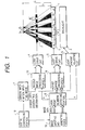
- Fig. 1 is a schematic diagram showing the arrangement of an image display apparatus according to the first embodiment of the present invention.
- a first light modulation panel 1 image displaying means, LCD 1 comprises a transmission type liquid crystal display element (LCD).
- a backlight 3 illumination means illuminates the first light modulation panel 1.
- a second light modulation panel 2 (light directivity controlling means, LCD 2) comprises a transmission type liquid crystal display element (LCD).
- the LCD 2 displays a parallax barrier on an area corresponding to a stripe image 11 in correspondence with the stripe image 11 displayed on the LCD 1.
- the parallax barrier is a pattern defined by alternately arranging vertical stripe-shaped light-transmitting portions and light-shielding portions in the horizontal direction, and guides light beams from stripe pixels constituting the stripe image 11 to predetermined observation positions, thus allowing an observer to stereoscopically observe the stripe image 11.
- the LCDs 1 and 2, the backlight 3, and the like correspond to constituting elements of a display portion.
- Fig. 1 shows the horizontal section of the display portion.
- the LCD 1 selectively displays a two-or three-dimensional image or displays them together as partial images on its display screen.
- Fig. 1 exemplifies a case wherein a three-dimensional partial image based on two view points is displayed, i.e., illustrates a stripe image 11 synthesized by arranging stripe pixels in the order of R1, L2, R3, L4, R5, L6,... from the left end of the screen.
- Fig. 2 is an explanatory view of the arrangement of the display portion of this embodiment. Referring to Fig.
- the display portion also comprises polarizing plates 21, 22, and 23, which have directions of polarization indicated by arrows.
- the directions of polarization of adjacent polarizing plates are perpendicular to each other.
- the display portion of this embodiment is constituted by arranging the polarizing plate 21, the LCD 1, the polarizing plate 22, the LCD 2, and the polarizing plate 23 to overlap each other in turn from the backlight 3 toward the observer side.
- the arrangement of the display portion of this embodiment is a so-called front barrier system in which the light directivity controlling means is arranged on the observer side of the image displaying means.
- observation width has a finite divergence at the observation position in practice, and these quantities are set after they are slightly modified.
- a stereoscopic image based on three or more view points can be displayed, and a partial parallax barrier to be displayed on the LCD 2 can be formed to match the state of the image.
- an LCD 2 drive circuit 4 drives the LCD 2
- an LCD 1 drive circuit 5 drives the LCD 1.
- a light amount adjusting circuit (light amount adjusting means) 6 adjusts the light emission amount of the backlight 3.
- a window information inputting means 7 is connected to the light amount adjusting circuit 6. Note that the entire display screen is handled as one window.
- An image inputting and generating means 19 inputs or generates a background image (as one partial image) and a partial image to be displayed on each window. At this time, if the partial image is a two-dimensional partial image, the means 19 inputs or generates only one image. However, if the partial image is a three-dimensional partial image, the means 19 inputs or generates parallax images corresponding to a plurality of view points.
- the view point number n will also be referred to as view point numbers information hereinafter.
- the view point numbers detecting portion 8 is connected to first and second image processing portions 9 and 10. Also, a system controlling portion 18 is connected to the window information inputting means 7 and the image inputting and generating means 19.
- Fig. 3A is a circuit diagram showing the arrangement of the first image processing portion 9 of the first embodiment.
- Each of i-th stripe image synthesizing circuits 11 i receives i-th image data and view point numbers information ni of the image data, divides n parallax images into a plurality of vertically elongated stripe pixels, and synthesizes a single stripe image by arranging the stripe pixels in a predetermined order.
- the input image data is a two-dimensional image
- each of the circuits 11 i directly outputs the input data to the next stage.
- Each of i-th image compressing circuits 12 i compresses stripe image data or two-dimensional image data output from the previous stage to a window size in accordance with window area designating information of a window for displaying the i-th image data.
- Pairs of stripe image synthesizing circuits 11 i and image compressing circuits 12 i are arranged and formed in parallel with each other in correspondence with the number of windows to be displayed on the LCD + 1 (corresponding to a background image).
- a window controlling circuit 13 sets a plurality of windows in a background image on the basis of image data from the image compressing circuits 12 i and the window area designating information, forms an image that displays the compressed stripe or two-dimensional images, and displays the formed image on the LCD 1 via the LCD 1 drive circuit 5.
- Fig. 3B is a circuit diagram showing the arrangement of the second image processing portion 10 of the first embodiment.
- the second image processing portion 10 has a barrier stripe generating circuit 14, which receives view point numbers information n from the view point numbers detecting portion 8 and window area designating information from the window information inputting means 7, generates, on the LCD 2, a partial parallax barrier (partial PB) corresponding to a three-dimensional partial image to be displayed on the LCD 1, and displays the partial PB on the LCD 2 via the LCD 2 drive circuit 4.
- a barrier stripe generating circuit 14 receives view point numbers information n from the view point numbers detecting portion 8 and window area designating information from the window information inputting means 7, generates, on the LCD 2, a partial parallax barrier (partial PB) corresponding to a three-dimensional partial image to be displayed on the LCD 1, and displays the partial PB on the LCD 2 via the LCD 2 drive circuit 4.
- partial PB partial parallax barrier
- Fig. 4 is a schematic diagram showing the arrangement of the backlight of this embodiment.
- Fig. 4 illustrates the backlight 3 portion as a front view.
- Figs. 5A and 5B are respectively a front view and a sectional view of one divided area of the backlight.
- the illumination surface of the backlight 3 is equally divided into four areas in the vertical direction and is also equally divided into four areas in the horizontal direction, i.e., is divided into a total of 16 areas 31 i,j .
- Each divided area 31 i,j has an inputting portion, and the light amount adjusting circuit 6 controls the light emission amount of each divided area 31 i,j by inputting a pulse signal via an inputting portion 32.
- Each divided area 31 i,j has fluorescent lamps 33, a reflection plate 34, and a scattering plate 35.
- the frequency of a pulse signal input to the fluorescent lamp lighting circuit of each divided area 31 i,j is changed to control the light emission amount of the fluorescent lamps.
- the reflection plate 34 is arranged on the rear surface of each divided area 31 i,j to improve illumination efficiency, and the scattering plate 35 is arranged on the front surface so as to illuminate the corresponding illumination portion of the LCD with uniform light.
- the backlight 3 constitutes a divisional illumination backlight, which can generate illumination light with a uniform luminance on the entire surface of each divided area, and can independently control the light emission amount of each divided area.
- the system controlling portion 18 inputs information associated with the number, sizes, positions, and the like of windows, i.e., window area designating information by controlling the window information inputting means 7. This information is output to the first and second image processing portions 9 and 10, and the light amount adjusting circuit 6.
- the system controlling portion 18 controls the image inputting and generating means 19 to generate or input a background image and partial images to be displayed on the windows.
- the means 19 generates or inputs one image data; if the partial image is a three-dimensional image, the means 19 generates or inputs parallax images corresponding to the view point number n.
- the input image has data indicating its view point number and a window to be displayed. An image data group including a plurality of such image data is parallelly input to the view point numbers detecting portion 8.
- the view point numbers detecting portion 8 detects view point numbers ni in units of image data, and parallelly outputs the detected view point numbers information ni to the first image processing portion 9 together with the image data. Also, the view point numbers detecting portion 8 outputs the detected view point numbers information ni to the second image processing portion 10 and the light amount adjusting circuit 6.
- the window controlling circuit 13 receives the image data compressed to the corresponding window sizes from the respective image compressing circuits 12 i , forms image information for one screen by appropriately determining the layout of these image data on the basis of the window area designating information, and outputs the formed image information to the LCD 1 drive circuit 5.
- the LCD 1 drive circuit 5 drives the LCD 1 on the basis of the image information, and displays a synthesized image on the display screen of the LCD 1.
- the second image processing portion 10 receives the view point numbers information and the window area designating information, generates image data of partial PBs corresponding to three-dimensional partial images to be displayed on the LCD 1, and outputs them to the LCD 2 drive circuit 4.
- the LCD 2 drive circuit 4 drives the LCD 2 on the basis of the input image data, and forms partial PBs on areas corresponding to the three-dimensional partial images on the display screen of the LCD 2.
- the light amount adjusting circuit 6 controls the light emission amounts of the respective divided areas of the backlight 3 on the basis of the window area designating information and the view point numbers information n.
- Figs. 6A to 6I are explanatory views showing the relationship among the light emission amounts of the respective divided areas of the backlight, partial images displayed on the LCD 1, and partial PBs displayed on the LCD 2. Numerals in the respective divided areas of the backlight represent the relative light amount ratios.
- the present invention is characterized in that the brightness levels of partial images to be observed by the observer are controlled by the light amount adjusting means in correspondence with the view point numbers, so as to set the partial images to have substantially equal brightness levels.
- “to set the partial images to have substantially equal brightness levels” means that when an original image which exhibits the maximum luminance on the entire screen is converted into a partial image and the partial image is displayed, the brightness level of the darkest partial image to be observed by the observer is set to be 80% or higher that of the brightest partial image.
- the boundary lines of partial images 1 and 2 (windows 1 and 2) and partial PBs 1 and 2 to be formed on the LCDs 2 and 1 are superposed on the dividing lines of the divided areas of the backlight 3.
- the threshold value of the moving amount of the mouse is determined in advance, and at the same time when the moving amount exceeds the threshold value, the window position is controlled to move in units of divided area sizes of the backlight.
- the threshold value of the moving amount of the mouse is similarly determined in advance, and at the same time when the moving amount exceeds the threshold value, the size of the window is controlled to change in units of divided area sizes of the backlight.
- the boundary lines of the partial images are always controlled to overlap the dividing lines of the areas of the backlight, when both three- and two-dimensional partial images are displayed on the screen, the brightness range (luminance range) of the entire screen can be maintained to be substantially constant.
- the light amount adjusting means controls the light emission amounts of the divided areas of the illumination means on the basis of the view point number information of partial images to be displayed on the first light modulation panel, thereby adjusting the brightness levels of partial images to be observed by the observer to substantially constant levels.
- a two-dimensional image may be displayed at the window position of the LCD 1, the corresponding partial PB to be displayed on the LCD 2 may be constituted by only light-transmitting portions, and the backlight 3 may be controlled to have a light amount used upon displaying a two-dimensional image independently of the view point number of an image in the window.
- a partial image and a partial PB with a brightness corresponding to the view point number may be displayed.
- the backlight 3 of this embodiment may be constituted by, e.g., a two-dimensional array LED divided to have the same pixel size as that of the LCDs 1 and 2, and may be controlled, so as to attain smooth movement of the window and smooth change in window size.
- a substantially constant luminance range of the entire screen can be maintained.
- a maximum 3-view point partial image is displayed on the image displaying means.
- the brightness of each partial image to be observed by the observer is about 0.4 as the above-mentioned value.
- a two- or three-dimensional image (both images are defined as partial images) is displayed on the entire screen to have a brightness of 0.4.
- the light amount adjustment before and after the switching operation may be inhibited.
- the brightness of each partial image is about 0.4 as the above-mentioned value.
- the above-mentioned display method that can maintain a substantially constant luminance range of the entire screen is used, although an image can be displayed to have a brightness of 1 as the above-mentioned value with respect to the performance of the backlight, the image is displayed to have a brightness of about 0.4. Therefore, a dark image is displayed on the entire screen relative to the performance of the backlight. For this reason, the above-mentioned method is not suitable for a backlight with low performance.
- the light amount adjusting circuit 7 upon reception of information indicating that the number of windows including a background image is 1 from the window information inputting means 7, the light amount adjusting circuit 7 performs light amount adjustment after the switching operation so as to turn on the backlight to exhibit its maximum luminance.
- the full-screen display state of a two- or three-dimensional image is switched to the mixed-display state, the above-mentioned light amount adjustment is performed in correspondence with the luminance of a partial image having the maximum view point number of those to be displayed together.
- the mixed-display state and the full-screen display state of a two- or three-dimensional image have a luminance difference, no luminance difference is generated in a single screen. Therefore, in the full-screen display mode of a partial image, an image can be displayed to have a maximum luminance.
- the light amount adjustment may be performed so that the state having a brightness of 0.4 as the above-mentioned value may be gradually switched to the state having the maximum luminance (about 1 as the above-mentioned value) over a predetermined period of time.
- Fig. 7 is a schematic diagram showing the arrangement of an image display apparatus according to the second embodiment of the present invention.
- Fig. 8 is a schematic diagram showing the arrangement of the first image processing portion 9 of the second embodiment.
- the display portion is constituted by arranging a light directivity controlling means (LCD 2) for displaying a partial parallax barrier and an image displaying means (LCD 1) for displaying a three-dimensional partial image from the backlight 3 toward the observer side, i.e., the display portion has a so-called rear barrier system in which the LCDs 1 and 2 replace each other in the first embodiment.
- LCD 2 light directivity controlling means
- LCD 1 image displaying means
- the backlight 3 comprises a backlight that has uniform brightness, and instead, light amount adjusting circuits (light amount adjusting means) 15 i are added in the first image processing portion 9 to control the brightness of a partial image to be displayed on the LCD 1.
- light amount adjusting circuits (light amount adjusting means) 15 i are added in the first image processing portion 9 to control the brightness of a partial image to be displayed on the LCD 1.
- Other arrangements are the same as those in the first embodiment.
- observation width has a finite divergence at the observation position in practice, and these quantities are set after they are slightly modified as in the arrangement of the first embodiment. Also, by appropriately changing the above-mentioned parameters, a stereoscopic image based on three or more view points can be displayed, needless to say.
- Each of the light amount adjusting circuits 15 i arranged in the first image processing portion of this embodiment converts the luminance values of pixels in input image data in correspondence with the view point numbers information of the image data, and outputs the converted image data to the next stage. Therefore, each light amount adjusting circuit 15 i also serves as a luminance adjusting means.
- the system controlling portion 18 inputs information associated with the number, sizes, positions, and the like of windows, i.e., window area designating information by controlling the window information inputting means 7. This information is output to the first and second image processing portions 9 and 10.
- the system controlling portion 18 controls the image inputting and generating means 19 to generate or input a background image (partial image) and partial images to be displayed on the windows.
- the means 19 if the partial image is a two-dimensional image, the means 19 generates or inputs one image data; if the partial image is a three-dimensional image, the means 19 generates or inputs parallax images corresponding to the view point number n.
- the input image has data indicating its view point number and a window to be displayed.
- An image data group including a plurality of such image data is parallelly input to the view point numbers detecting portion (view point numbers detecting means) 8.
- the view point numbers detecting portion 8 detects view point numbers ni in units of image data, and parallelly outputs the detected view point numbers information ni to the first image processing portion 9 together with the image data. Also, the view point numbers detecting portion 8 outputs the detected view point numbers information ni to the second image processing portion 10.
- Each of the light amount adjusting circuits 15 i appropriately converts the luminance upon displaying image data on the basis of the view point numbers information, and outputs the converted data to a corresponding one of the stripe image synthesizing circuits 11 i .
- an image data group input to the first image processing portion 9 includes three different types of images, i.e., a 1-view point partial image, a 2-view point partial image, and a 3-view point partial image, and these image data have a maximum brightness level "100"
- the luminance values in units of pixels of the 3-view point partial image are left unchanged
- the luminance values in units of pixels of the 2-view point partial image are converted to have values 70% of the original values
- the luminance values in units of pixels of the 1-view point partial image are converted to have values 40% of the original values.
- these image data are output to the corresponding stripe image synthesizing circuits 11 i .
- the window controlling circuit 13 receives the image data compressed to the corresponding window sizes from the respective image compressing circuits 12 i , forms image information for one screen by appropriately determining the layout of these image data on the basis of the window area designating information, and outputs the formed image information to the LCD 1 drive circuit 5.
- the LCD 1 drive circuit 5 drives the LCD 1 on the basis of the image information, and displays an image, on which the respective partial images are inserted in the corresponding windows, on the display screen of the LCD 1.
- a partial image having luminance values falling within the range from 0 to 40 is formed on an area where a 1-view point partial image is to be displayed
- a partial image having luminance values falling within the range from 0 to 70 is formed on an area where a 2-view point partial image is to be displayed
- a partial image having luminance values falling within the range from 0 to 100 is formed on an area where a 3-view point partial image is to be displayed.
- the second image processing portion 10 receives the view point numbers information ni and the window area designating information, generates image data of partial PBs corresponding to three-dimensional partial images to be displayed on the LCD 1, and outputs them to the LCD 2 drive circuit 4.
- the LCD 2 drive circuit 4 drives the LCD 2 on the basis of the input image data, and forms partial PBs at appropriate positions on the display screen of the LCD 2.
- the luminance of the entire screen can be appropriately maintained even when three- and two-dimensional partial images are displayed together on the screen.
- the LCD 1 is illuminated with light emitted by the backlight having uniform brightness, and each partial image is displayed on the LCD 1 by controlling the luminance values in units of pixels of the partial image in correspondence with its view point number ni by the light amount adjusting means, the brightness levels of partial images to be observed by the observer can be maintained to be nearly constant. Even when the display state is switched to the full-screen display state of a two- or three-dimensional image, the luminance range on the entire screen can be maintained to be substantially constant by the method described in the first embodiment.
- the movement of the window and the change in size of the window are not limited by the divided area size of the backlight unlike in the first embodiment, the movement of the window and the change in size of the window can always be smoothly performed.
- the display portion adopts the front barrier type arrangement, and its brightness adjustment is attained by adjusting the light emission amount of the backlight
- the display portion adopts the rear barrier type arrangement, and its brightness adjustment is attained by adjusting the luminance values in units of pixels of each partial image.
- the same brightness adjustment as in the first embodiment may be performed in the arrangement of the display portion of the second embodiment, while the same brightness adjustment as in the second embodiment may be performed in the arrangement of the display portion of the first embodiment.
- a further description thereof will not be made to avoid redundancy.
- Fig. 9 is a schematic diagram showing the arrangement of an image display apparatus according to the third embodiment of the present invention.
- Fig. 10 is a schematic diagram showing the arrangement of the circuit of the second image processing portion 10 of the third embodiment.
- the difference from the second embodiment is that the first image processing portion 9 has no light amount adjusting circuits 15 i , and instead, a light amount adjusting circuit (light amount adjusting means) 16 is added in the second image processing portion 10.
- a light amount adjusting circuit (light amount adjusting means) 16 is added in the second image processing portion 10.
- the light amount adjusting circuit 16 changes the transmittance of the light-transmitting portions in each partial PB corresponding to a partial image on the basis of the view point numbers information of the partial image.
- the system controlling portion 18 inputs information associated with the number, sizes, positions, and the like of windows, i.e., window area designating information by controlling the window information inputting means 7. This information is output to the first and second image processing portions 9 and 10.
- the system controlling portion 18 controls the image inputting and generating means 19 to generate or input a background image (partial image) and partial images to be displayed on the windows.
- the means 19 if the partial image is a two-dimensional image, the means 19 generates or inputs one image data; if the partial image is a three-dimensional image, the means 19 generates or inputs parallax images corresponding to the view point number n.
- the input image has data indicating its view point number and a window to be displayed. An image data group including a plurality of such image data is parallelly input to the view point numbers detecting portion 8.
- the view point numbers detecting portion 8 detects view point numbers ni in units of image data, and parallelly outputs the detected view point numbers information ni to the first image processing portion 9 together with the image data. Also, the view point numbers detecting portion 8 outputs the detected view point numbers information ni to the second image processing portion 10.
- the window controlling circuit 13 receives the image data compressed to the corresponding window sizes from the respective image compressing circuits 12 i , forms image information for one screen by appropriately determining the layout of these image data on the basis of the window area designating information, and outputs the formed image information to the LCD 1 drive circuit 5.
- the LCD 1 drive circuit 5 drives the LCD 1 on the basis of the image information, and displays an image on the display screen of the LCD 1.
- the second image processing portion 10 generates image data of a partial PB constituted by light-transmitting portions and light-shielding portions to be displayed on the LCD 2 on the basis of the view point numbers information ni and the window area designating information from the view point numbers detecting portion 8, and outputs the generated image data to the light amount adjusting circuit 16.
- the light amount adjusting circuit 16 changes the transmittance of the light-transmitting portions of the image data (changes the display density) in correspondence with the view point numbers information ni, and outputs the image data to the LCD 2 drive circuit 4.
- the LCD 2 drive circuit 4 drives the LCD 2 on the basis of the image data to form, on the screen of the LCD 2, partial PBs constituted by light-transmitting portions of different transmittances in correspondence with the view point numbers of the partial images displayed on the LCD 1.
- Figs. 11A and 11B show display examples of the LCDs 1 and 2 in this embodiment.
- the LCD 1 displays a 1-view point partial image as a background image, and also displays window 1 for a 2-view point partial image and window 2 for a 3-view point partial image.
- the LCD 2 displays partial PB 1 corresponding to two view points on an area corresponding to the 2-view point partial image (window 1) on the LCD 1 and partial PB 2 corresponding to three view points on an area corresponding to the 3-view point partial image (window 2) on the LCD 1.
- the light-transmitting portions and light-shielding portions of partial PB 2 are set so that light can be focused at three predetermined observation positions on the observer side via stripe pixels constituting the 3-view point partial image.
- the light-transmitting portions and light-shielding portions of partial PB 1 are set so that light can be focused at two predetermined observation positions on the observer side via stripe pixels constituting the 2-view point partial image.
- the transmittance of the light-transmitting portions of the partial PB 1 corresponding to the 2-view point partial image is set to be 70 % of that of the partial PB 2 corresponding to the 3-view point partial image. Also, the transmittance of the light-transmitting portions of the partial PB corresponding to the 1-view point partial image is set to be 40 % of that of the partial PB 2 corresponding to the 3-view point partial image.
- the luminance of the entire screen can be appropriately maintained even when three- and two-dimensional partial images are displayed together on the screen.
- the transmittance of the light-transmitting portions of a partial PB to be displayed on the LCD 2 is adjusted by the light amount adjusting means in correspondence with the view point number of the corresponding partial image, the brightness levels of partial images to be observed by the observer can always be maintained to be substantially constant when three- and two-dimensional partial images are displayed together on the screen.
- the luminance range on the entire screen can be maintained to be substantially constant by the method described in the first embodiment.
- the movement of a window and the change in size of the window can be attained in units of pixels of the LCD 2 as compared to the arrangement of the first embodiment, the movement of a window and the change in size of the window can always be smoothly attained.
- the display portion is constituted by arranging the LCD 2 and the LCD 1 from the backlight 3 side, and the brightness adjustment of a partial image is executed by adjusting the transmittance of the light-transmitting portions of a partial PB displayed on the LCD 2. Also, the same brightness adjustment as in this embodiment may be performed in the arrangement of the display portion of the first embodiment.
- Fig. 12 is a schematic diagram showing the arrangement of a stereoscopic image display apparatus according to the fourth embodiment of the present invention.
- the difference from the third embodiment is that a self-emitting type element 25 is used in place of the LCD 2 and the backlight 3 of the third embodiment, and a CRT driving circuit 4' is arranged in place of the drive circuit 4.
- This embodiment uses a CRT as the self-emitting type element 25.
- a partial parallax barrier is formed by alternately arranging stripe-shaped light-emitting portions and non-light-emitting portions on an area, corresponding to a partial image, on the tube surface of the CRT 25.
- the CRT 25 has a function of a light directivity controlling means.
- the flow of processing in this embodiment will be described below with reference to Fig. 12.
- the first image processing portion 9 of this embodiment is the one from which the light amount adjusting circuits 15 i are excluded from that of the second embodiment (see Fig. 8).
- the second image processing portion 10 of this embodiment is the same as that of the third embodiment, and Fig. 10 is a schematic diagram showing its arrangement.
- the system controlling portion 18 inputs information associated with the number, sizes, positions, and the like of windows, i.e., window area designating information by controlling the window information inputting means 7. This information is output to the first and second image processing portions 9 and 10.
- the system controlling portion 18 controls the image inputting and generating means 19 to generate or input a background image (partial image) and partial images to be displayed on the windows.
- the means 19 if the partial image is a two-dimensional image, the means 19 generates or inputs one image data; if the partial image is a three-dimensional image, the means 19 generates or inputs parallax images corresponding to the view point number n.
- the input image has data indicating its view point number and a window to be displayed. An image data group including a plurality of such image data is parallelly input to the view point numbers detecting portion 8.
- the view point numbers detecting portion 8 detects view point numbers ni in units of image data, and parallelly outputs the detected view point numbers information ni to the first image processing portion 9 together with the image data. Also, the view point numbers detecting portion 8 outputs the detected view point numbers information ni to the second image processing portion 10.
- the window controlling circuit 13 receives the image data compressed to the corresponding window sizes from the respective image compressing circuits 12 i , forms image information for one screen by appropriately determining the layout of these image data on the basis of the window area designating information, and outputs the formed image information to the LCD 1 drive circuit 5.
- the LCD 1 drive circuit 5 drives the LCD 1 on the basis of the image information, and displays a synthesized image on the display screen of the LCD 1.
- the second image processing portion 10 generates image data of a partial PB constituted by light-emitting portions and non-light-emitting portions to be displayed on a tube surface 26 of the CRT 25 on the basis of the view point numbers information ni and the window area designating information from the view point numbers detecting portion 8, and outputs the generated image data to the light amount adjusting circuit 16.
- the light amount adjusting circuit 16 changes the luminance value of the light-emitting portions in the image data (changes the display density) in correspondence with the view point numbers information ni, and outputs the image data to the CRT driving circuit 4'.
- the CRT driving circuit 4' drives the CRT 25 on the basis of the image data to form, on the tube surface of the CRT 25, partial PBs constituted by light-emitting portions of different luminance values in correspondence with the view point numbers of the partial images displayed on the LCD 1.
- Figs. 13A and 13B show display examples of the CRT 25 and the LCD 1 in this embodiment.
- the LCD 1 displays a 1-view point partial image as a background image, and also displays window 1 for a 2-view point partial image and window 2 for a 3-view point partial image.
- the CRT 25 displays partial PB 1 corresponding to two view points on an area corresponding to the 2-view point partial image (window 1) on the LCD 1 and partial PB 2 corresponding to three view points on an area corresponding to the 3-view point partial image (window 2) on the LCD 1.
- the light-emitting portions and non-light-emitting portions of partial PB 2 are set so that light can be focused at predetermined three observation positions on the observer side via stripe pixels constituting the 3-view point partial image.
- the light-emitting portions and non-light-emitting portions of partial PB 1 are set so that light can be focused at predetermined two observation positions on the observer side via stripe pixels constituting the 2-view point partial image.
- the luminance value of light-emitting portions of the partial PB 1 corresonding to the 2-view point partial image is set to be 70 % of that of the partial PB 2 corresonding to the 3-view point partial image. Also, the luminance value of light-emitting portions of the partial PB corresponding to the 1-view point partial image is set to be 40 % of that of the partial PB 2 corresponding to the 3-view point partial image.
- the luminance of the entire screen can be appropriately maintained even when three- and two-dimensional partial images are displayed together on the screen.
- the luminance value of the light-emitting portions of a partial PB displayed on the CRT 25 is controlled by the light amount adjusting means in correspondence with the view point number of the corresponding partial image, the brightness levels of partial images to be observed by the observer can always be maintained to be substantially constant when three- and two-dimensional partial images are displayed together on the screen.
- the luminance range on the entire screen can be maintained to be substantially constant by the method described in the first embodiment.
- the display portion is constituted by the LCD 1 serving as the image displaying means and the CRT 25 serving as the light directivity controlling means.
- the CRT 25 may be used in place of the backlight 3 and the LCD 2 in the second embodiment, and the CRT 25 may be used in place of the backlight 3 and the LCD 1 in the first embodiment.
- a repetitive description thereof will be avoided here.
- the arrangement of the display portion, the combination of the display method and the light amount adjusting means, and the like described in the above embodiments are not particularly limited, and combinations described in the scope of the claims of the present invention are available.
Landscapes
- Engineering & Computer Science (AREA)
- Multimedia (AREA)
- Signal Processing (AREA)
- Physics & Mathematics (AREA)
- General Physics & Mathematics (AREA)
- Computer Hardware Design (AREA)
- Theoretical Computer Science (AREA)
- Optics & Photonics (AREA)
- Testing, Inspecting, Measuring Of Stereoscopic Televisions And Televisions (AREA)
Applications Claiming Priority (6)
| Application Number | Priority Date | Filing Date | Title |
|---|---|---|---|
| JP18867095 | 1995-06-29 | ||
| JP18867095 | 1995-06-29 | ||
| JP188670/95 | 1995-06-29 | ||
| JP8115718A JPH0973049A (ja) | 1995-06-29 | 1996-04-12 | 画像表示方法及びそれを用いた画像表示装置 |
| JP115718/96 | 1996-04-12 | ||
| JP11571896 | 1996-04-12 |
Publications (3)
| Publication Number | Publication Date |
|---|---|
| EP0751690A2 true EP0751690A2 (fr) | 1997-01-02 |
| EP0751690A3 EP0751690A3 (fr) | 1997-07-30 |
| EP0751690B1 EP0751690B1 (fr) | 2002-09-18 |
Family
ID=26454182
Family Applications (1)
| Application Number | Title | Priority Date | Filing Date |
|---|---|---|---|
| EP96304744A Expired - Lifetime EP0751690B1 (fr) | 1995-06-29 | 1996-06-27 | Affichage d'image stéréoscopique |
Country Status (4)
| Country | Link |
|---|---|
| US (1) | US5945965A (fr) |
| EP (1) | EP0751690B1 (fr) |
| JP (1) | JPH0973049A (fr) |
| DE (1) | DE69623702T2 (fr) |
Cited By (15)
| Publication number | Priority date | Publication date | Assignee | Title |
|---|---|---|---|---|
| GB2318424A (en) * | 1996-10-21 | 1998-04-22 | Reuben Hoppenstein | Stereoscopic images using a viewing grid |
| JPH10232665A (ja) * | 1997-02-20 | 1998-09-02 | Canon Inc | 表示制御装置及び方法 |
| EP0860807A3 (fr) * | 1997-02-10 | 1999-06-02 | Canon Kabushiki Kaisha | Méthode et système d'affichage mixte d'images à deux ou trois dimensions |
| GB2342183A (en) * | 1996-10-21 | 2000-04-05 | Reuben Hoppenstein | Stereoscopic images using a viewing grid |
| EP1460858A1 (fr) * | 2003-01-24 | 2004-09-22 | Pioneer Corporation | Appareil pour affichage d'image tri-dimensionnel |
| WO2006018773A1 (fr) * | 2004-08-17 | 2006-02-23 | Koninklijke Philips Electronics N.V. | Detection du mode de presentation |
| EP1250013A4 (fr) * | 1999-09-02 | 2006-05-24 | Obschestvo S Ogranichennoi Otv | Procede d'affichage d'une image d'un objet |
| EP1501317A4 (fr) * | 2002-04-25 | 2006-06-21 | Sharp Kk | Dispositif de creation de donnees image, dispositif de reproduction de donnees image, et support d'enregistrement de donnees image |
| EP1848223A3 (fr) * | 2006-04-17 | 2008-01-23 | Samsung SDI Co., Ltd. | Dispositif d'affichage d'images en 2D/3D, dispositif d'affichage d'image électronique et son procédé de commande |
| WO2009105544A3 (fr) * | 2008-02-19 | 2009-10-15 | The Board Of Trustees Of The University Of Illinois | Écran interactif de grand format à résolution élevée |
| EP2065880A4 (fr) * | 2006-09-20 | 2010-04-28 | Sharp Kk | Dispositif d'affichage |
| WO2013153418A1 (fr) * | 2012-04-12 | 2013-10-17 | Sony Mobile Communications Ab | Système d'affichage d'image tridimensionnelle (3d) amélioré |
| US8723920B1 (en) | 2011-07-05 | 2014-05-13 | 3-D Virtual Lens Technologies, Llc | Encoding process for multidimensional display |
| US9743071B2 (en) | 2011-02-14 | 2017-08-22 | Semiconductor Energy Laboratory Co., Ltd. | Display device |
| EP3835850A4 (fr) * | 2018-08-08 | 2022-04-20 | Kyocera Corporation | Dispositif d'affichage d'image, système d'affichage d'image et corps mobile |
Families Citing this family (114)
| Publication number | Priority date | Publication date | Assignee | Title |
|---|---|---|---|---|
| DE69806692T2 (de) * | 1997-05-27 | 2003-03-20 | Sanyo Electric Co., Ltd. | Stereoskopische Anzeigevorrichtung mit Benutzerspurfolgesystem |
| US6747610B1 (en) * | 1997-07-22 | 2004-06-08 | Sanyo Electric Co., Ltd. | Stereoscopic image display apparatus capable of selectively displaying desired stereoscopic image |
| US6215532B1 (en) * | 1998-07-27 | 2001-04-10 | Mixed Reality Systems Laboratory Inc. | Image observing apparatus for observing outside information superposed with a display image |
| US7085049B2 (en) | 1999-07-19 | 2006-08-01 | Lg.Philips Lcd Co., Ltd. | Multi-mode stereoscopic image display method and apparatus |
| US6985290B2 (en) * | 1999-12-08 | 2006-01-10 | Neurok Llc | Visualization of three dimensional images and multi aspect imaging |
| US7224526B2 (en) * | 1999-12-08 | 2007-05-29 | Neurok Llc | Three-dimensional free space image projection employing Fresnel lenses |
| US6717728B2 (en) * | 1999-12-08 | 2004-04-06 | Neurok Llc | System and method for visualization of stereo and multi aspect images |
| AU2001237338A1 (en) * | 2000-01-25 | 2001-08-07 | 4D-Vision Gmbh | Method and system for the three-dimensional representation |
| US20020101658A1 (en) * | 2001-01-29 | 2002-08-01 | Reuben Hoppenstein | Electronic virtual lens for observing 3-D or 4-D images |
| WO2003058979A2 (fr) * | 2002-01-04 | 2003-07-17 | Neurok Llc | Projection d'images tridimensionnelles au moyen d'ecrans retroreflechissants |
| JP2003337303A (ja) * | 2002-05-17 | 2003-11-28 | Canon Inc | 立体画像表示装置および立体画像表示システム |
| KR100637303B1 (ko) * | 2002-09-26 | 2006-10-24 | 샤프 가부시키가이샤 | 2d/3d 전환형 액정 표시 패널, 및 2d/3d 전환형 액정표시 장치 |
| JP2004191490A (ja) * | 2002-12-09 | 2004-07-08 | Hitachi Displays Ltd | 液晶表示装置 |
| US7663570B2 (en) | 2003-02-27 | 2010-02-16 | Nec Corporation | Image display device, portable terminal device and display panel |
| JP4677175B2 (ja) | 2003-03-24 | 2011-04-27 | シャープ株式会社 | 画像処理装置、画像撮像システム、画像表示システム、画像撮像表示システム、画像処理プログラム、及び画像処理プログラムを記録したコンピュータ読み取り可能な記録媒体 |
| TWI277769B (en) * | 2003-03-25 | 2007-04-01 | Sanyo Electric Co | The stereoscopic video display device and its manufacturing method |
| WO2004107765A1 (fr) * | 2003-05-28 | 2004-12-09 | Sanyo Electric Co., Ltd. | Afficheur video tridimensionnel, dispositif de traitement de donnees textuelles, programme, et support de stockage |
| DE10325146A1 (de) | 2003-05-30 | 2004-12-16 | X3D Technologies Gmbh | Verfahren und Anordnung zur räumlichen Darstellung |
| JP4200056B2 (ja) * | 2003-06-17 | 2008-12-24 | 有限会社シーフォン | 表示装置 |
| US7649688B2 (en) * | 2003-10-08 | 2010-01-19 | Louis Racette | Auto-stereo three-dimensional images |
| US20050088516A1 (en) * | 2003-10-23 | 2005-04-28 | Myoung-Seop Song | Display device for both two-dimensional and three-dimensional images and display method thereof |
| JP2005175538A (ja) * | 2003-12-05 | 2005-06-30 | Sharp Corp | 立体映像表示装置及び映像表示方法 |
| JP4536408B2 (ja) | 2004-03-30 | 2010-09-01 | ルネサスエレクトロニクス株式会社 | 集積回路装置 |
| US20050280894A1 (en) * | 2004-04-02 | 2005-12-22 | David Hartkop | Apparatus for creating a scanning-column backlight in a scanning aperture display device |
| KR100708838B1 (ko) | 2004-06-30 | 2007-04-17 | 삼성에스디아이 주식회사 | 입체 영상 표시 장치 및 그 구동 방법 |
| KR100649251B1 (ko) * | 2004-06-30 | 2006-11-24 | 삼성에스디아이 주식회사 | 입체 영상 표시 장치 및 그 구동 방법 |
| US20060050068A1 (en) * | 2004-08-25 | 2006-03-09 | Pitney Bowes Incorporated | Apparatus for producing three-dimensional static or dynamic images |
| US8094103B2 (en) * | 2004-08-31 | 2012-01-10 | Sharp Kabushiki Kaisha | Viewing-angle control device, display apparatus, method for controlling viewing-angle control device, viewing-angle control program, and storage medium storing the program |
| US7834834B2 (en) * | 2004-09-07 | 2010-11-16 | Sharp Kabushiki Kaisha | Display device, viewing angle control device, and electronic apparatus |
| US7817106B2 (en) * | 2004-09-15 | 2010-10-19 | Sharp Kabushiki Kaisha | Display device, viewing angle control device, and electronic apparatus |
| US8031273B2 (en) * | 2004-09-17 | 2011-10-04 | Sharp Kabushiki Kaisha | Display device, viewing angle control device, and electronic device |
| US8184145B2 (en) * | 2004-10-04 | 2012-05-22 | Sharp Kabushiki Kaisha | Display device and electronic apparatus |
| US20060087556A1 (en) * | 2004-10-21 | 2006-04-27 | Kazunari Era | Stereoscopic image display device |
| WO2006054518A1 (fr) * | 2004-11-18 | 2006-05-26 | Pioneer Corporation | Dispositif d’affichage 3d |
| WO2006054516A1 (fr) * | 2004-11-18 | 2006-05-26 | Pioneer Corporation | Appareil d’affichage stéréoscopique |
| WO2006054517A1 (fr) * | 2004-11-18 | 2006-05-26 | Pioneer Corporation | Appareil d’affichage stéréoscopique |
| CN101088298B (zh) * | 2004-12-22 | 2010-12-15 | 马斯特图像3D亚洲有限责任公司 | 视差阻挡型立体显示设备 |
| TWI264600B (en) * | 2005-02-03 | 2006-10-21 | Au Optronics Corp | 2D/3D display and method for forming 3D images |
| TWI261099B (en) * | 2005-02-17 | 2006-09-01 | Au Optronics Corp | Backlight modules |
| JP2006276822A (ja) * | 2005-03-02 | 2006-10-12 | Hitachi Displays Ltd | 表示装置 |
| JP2007017768A (ja) * | 2005-07-08 | 2007-01-25 | Hitachi Displays Ltd | 表示装置 |
| JP4561525B2 (ja) * | 2005-08-10 | 2010-10-13 | セイコーエプソン株式会社 | 表示装置および遊技機 |
| KR100647517B1 (ko) | 2005-08-26 | 2006-11-23 | (주)마스터이미지 | 셀 구조 패러랙스-배리어 및 이를 이용하는 입체영상 표시장치 |
| US8531439B2 (en) * | 2005-09-28 | 2013-09-10 | Koninklijke Philips N.V. | Switchable display device |
| JP4339319B2 (ja) * | 2005-09-29 | 2009-10-07 | シャープ株式会社 | 表示装置および電子機器 |
| KR101291860B1 (ko) * | 2005-12-28 | 2013-07-31 | 엘지디스플레이 주식회사 | 2차원 영상 및 3차원 영상 디스플레이장치, 그 제조방법 |
| JP5006587B2 (ja) * | 2006-07-05 | 2012-08-22 | 株式会社エヌ・ティ・ティ・ドコモ | 画像提示装置および画像提示方法 |
| CN100505894C (zh) * | 2006-08-24 | 2009-06-24 | 胜华科技股份有限公司 | 强化无分辨率丧失的3d立体显示亮度的驱动方法 |
| US20080084521A1 (en) * | 2006-10-06 | 2008-04-10 | Stanley Electric Co., Ltd. | Field sequentially driven liquid crystal display device |
| KR100859694B1 (ko) * | 2007-04-12 | 2008-09-23 | 삼성에스디아이 주식회사 | 평면/입체 액정 표시장치 및 그 구동방법 |
| KR101329164B1 (ko) * | 2007-07-02 | 2013-11-14 | 엘지디스플레이 주식회사 | 집적영상방식의 3차원 영상표시장치 |
| JP5045308B2 (ja) * | 2007-08-27 | 2012-10-10 | 株式会社セガ | 画像表示制御プログラム及び画像表示制御装置 |
| JP4906680B2 (ja) * | 2007-11-02 | 2012-03-28 | キヤノン株式会社 | 画像表示装置 |
| US8842064B2 (en) * | 2007-12-20 | 2014-09-23 | Reald Inc. | Intra-pixel illumination system |
| GB2457691A (en) | 2008-02-21 | 2009-08-26 | Sharp Kk | Display with regions simultaneously operable in different viewing modes |
| KR100918065B1 (ko) * | 2008-03-31 | 2009-09-18 | 삼성모바일디스플레이주식회사 | 표시 장치 및 그의 구동 방법 |
| JP4979136B2 (ja) * | 2008-06-03 | 2012-07-18 | Necカシオモバイルコミュニケーションズ株式会社 | 放送受信端末装置及びプログラム |
| JP5230299B2 (ja) * | 2008-08-22 | 2013-07-10 | 三菱電機株式会社 | 映像表示装置及び映像表示方法 |
| TWI328714B (en) * | 2008-10-09 | 2010-08-11 | Au Optronics Corp | Switchable two and three dimensional display |
| JP4457323B2 (ja) * | 2008-10-09 | 2010-04-28 | 健治 吉田 | 遊技ゲーム機 |
| JP4818351B2 (ja) * | 2008-12-25 | 2011-11-16 | 株式会社東芝 | 画像処理装置及び画像表示装置 |
| US20100238274A1 (en) * | 2009-03-16 | 2010-09-23 | Lg Electronics Inc. | Method of displaying three-dimensional image data and an apparatus of processing three-dimensional image data |
| JP2010217650A (ja) * | 2009-03-18 | 2010-09-30 | Seiko Epson Corp | 電気光学装置及び電子機器 |
| JP2010231045A (ja) * | 2009-03-27 | 2010-10-14 | Casio Computer Co Ltd | 画像表示装置、画像表示プログラム及び画像表示方法 |
| JP5702054B2 (ja) * | 2009-03-31 | 2015-04-15 | ソニー株式会社 | 表示装置及び表示方法 |
| US8368707B2 (en) * | 2009-05-18 | 2013-02-05 | Apple Inc. | Memory management based on automatic full-screen detection |
| DE102009034355B3 (de) * | 2009-07-17 | 2011-01-27 | Fraunhofer-Gesellschaft zur Förderung der angewandten Forschung e.V. | Monitor und Verfahren zum Darstellen autostereoskopisch wahrnehmbarer Bilder |
| JP5343785B2 (ja) * | 2009-09-17 | 2013-11-13 | ソニー株式会社 | 画像信号処理装置、送信装置、画像信号処理方法、プログラム、および画像信号処理システム |
| KR20120095424A (ko) * | 2009-11-17 | 2012-08-28 | 에테하 쭈리히 | 투명한 무안경 입체영상 디스플레이 장치 및 방법 |
| KR101651270B1 (ko) * | 2009-12-24 | 2016-08-29 | 삼성디스플레이 주식회사 | 입체 영상 표시 장치 및 그 구동 방법 |
| US8854531B2 (en) * | 2009-12-31 | 2014-10-07 | Broadcom Corporation | Multiple remote controllers that each simultaneously controls a different visual presentation of a 2D/3D display |
| TW201122993A (en) * | 2009-12-31 | 2011-07-01 | Acer Inc | Electric apparatus and 3D object display method thereof |
| US8964013B2 (en) * | 2009-12-31 | 2015-02-24 | Broadcom Corporation | Display with elastic light manipulator |
| US8823782B2 (en) | 2009-12-31 | 2014-09-02 | Broadcom Corporation | Remote control with integrated position, viewer identification and optical and audio test |
| US9247286B2 (en) * | 2009-12-31 | 2016-01-26 | Broadcom Corporation | Frame formatting supporting mixed two and three dimensional video data communication |
| TW201133032A (en) * | 2010-03-23 | 2011-10-01 | Unique Instr Co Ltd | Multi-function LCD parallax grating device |
| CN101795420B (zh) * | 2010-04-07 | 2012-12-26 | 昆山龙腾光电有限公司 | 立体图像显示系统及其控制方法 |
| TWI417866B (zh) * | 2010-04-22 | 2013-12-01 | Chunghwa Picture Tubes Ltd | 立體畫面顯示方法及其立體顯示裝置 |
| JP5659589B2 (ja) * | 2010-07-13 | 2015-01-28 | 株式会社ニコン | 表示装置および制御方法 |
| US8446461B2 (en) * | 2010-07-23 | 2013-05-21 | Superd Co. Ltd. | Three-dimensional (3D) display method and system |
| JP5053427B2 (ja) * | 2010-08-09 | 2012-10-17 | シャープ株式会社 | 表示装置 |
| JP4856775B2 (ja) * | 2010-08-09 | 2012-01-18 | 学校法人早稲田大学 | 立体映像呈示装置 |
| JP5648361B2 (ja) * | 2010-08-10 | 2015-01-07 | ソニー株式会社 | 表示装置 |
| JP5568409B2 (ja) * | 2010-08-24 | 2014-08-06 | 株式会社日立製作所 | 立体表示装置 |
| TW201209791A (en) * | 2010-08-30 | 2012-03-01 | Ind Tech Res Inst | Two mode image displaying apparatus and adjustment method of image brightness |
| JP2012063704A (ja) * | 2010-09-17 | 2012-03-29 | Sony Corp | 表示装置 |
| US8471908B2 (en) | 2010-10-18 | 2013-06-25 | GM Global Technology Operations LLC | Three-dimensional mirror display system for a vehicle and method |
| WO2012056692A1 (fr) * | 2010-10-28 | 2012-05-03 | 富士フイルム株式会社 | Dispositif d'affichage d'image 3d et procédé d'affichage d'image 3d |
| KR101670927B1 (ko) * | 2010-11-05 | 2016-11-01 | 삼성전자주식회사 | 디스플레이 장치 및 방법 |
| WO2012086532A1 (fr) * | 2010-12-24 | 2012-06-28 | シャープ株式会社 | Dispositif d'affichage |
| JP5161999B2 (ja) * | 2011-04-19 | 2013-03-13 | 株式会社東芝 | 電子機器、表示制御方法及び表示制御プログラム |
| TWI425498B (zh) * | 2011-05-04 | 2014-02-01 | Au Optronics Corp | 關聯於雙影像應用的影音播放系統及其方法 |
| JP5653299B2 (ja) * | 2011-06-09 | 2015-01-14 | 株式会社ジャパンディスプレイ | 液晶表示装置 |
| JP2013057824A (ja) * | 2011-09-08 | 2013-03-28 | Sony Corp | 表示装置、表示方法、および電子機器 |
| TWI449954B (zh) * | 2011-10-28 | 2014-08-21 | Chunghwa Picture Tubes Ltd | 三維立體顯示方法、顯示裝置及顯示系統 |
| US9055289B2 (en) * | 2011-11-23 | 2015-06-09 | Korea Institute Of Science And Technology | 3D display system |
| JP2013174665A (ja) * | 2012-02-23 | 2013-09-05 | Toshiba Corp | 情報処理装置、画質補正の制御方法およびプログラム |
| JP2012178836A (ja) * | 2012-03-30 | 2012-09-13 | Sharp Corp | 表示装置、表示制御方法、表示制御プログラム、及びコンピュータ読み取り可能な記録媒体 |
| JP2014002241A (ja) * | 2012-06-18 | 2014-01-09 | Sony Corp | 立体表示用光学デバイスおよび立体表示ユニット |
| US8982459B1 (en) | 2012-06-20 | 2015-03-17 | Rawles Llc | Passive projection screen for presenting projected images in 3D |
| JP5526196B2 (ja) * | 2012-07-18 | 2014-06-18 | 株式会社東芝 | 電子機器および映像表示方法 |
| JP5433774B2 (ja) * | 2012-12-05 | 2014-03-05 | 株式会社東芝 | 電子機器、表示制御方法及び表示制御プログラム |
| WO2014136140A1 (fr) * | 2013-03-05 | 2014-09-12 | パナソニック株式会社 | Dispositif et procédé de traitement vidéo |
| CN103236074B (zh) * | 2013-03-25 | 2015-12-23 | 深圳超多维光电子有限公司 | 一种2d/3d图像处理方法及装置 |
| US10303242B2 (en) | 2014-01-06 | 2019-05-28 | Avegant Corp. | Media chair apparatus, system, and method |
| US10409079B2 (en) | 2014-01-06 | 2019-09-10 | Avegant Corp. | Apparatus, system, and method for displaying an image using a plate |
| US9823474B2 (en) | 2015-04-02 | 2017-11-21 | Avegant Corp. | System, apparatus, and method for displaying an image with a wider field of view |
| US9995857B2 (en) | 2015-04-03 | 2018-06-12 | Avegant Corp. | System, apparatus, and method for displaying an image using focal modulation |
| GB2540377A (en) * | 2015-07-14 | 2017-01-18 | Sharp Kk | Parallax barrier with independently controllable regions |
| GB2540376A (en) * | 2015-07-14 | 2017-01-18 | Sharp Kk | Parallax barrier with independently controllable regions |
| CN107797297B (zh) * | 2016-08-30 | 2020-03-31 | 京东方科技集团股份有限公司 | 显示装置及其显示方法 |
| CN106707533A (zh) * | 2017-03-24 | 2017-05-24 | 京东方科技集团股份有限公司 | 一种三维显示装置 |
| JP2020178307A (ja) * | 2019-04-22 | 2020-10-29 | 株式会社ジャパンディスプレイ | 表示装置 |
| JP2024008154A (ja) * | 2022-07-07 | 2024-01-19 | キヤノン株式会社 | 画像処理装置、表示装置および画像処理方法 |
Family Cites Families (7)
| Publication number | Priority date | Publication date | Assignee | Title |
|---|---|---|---|---|
| US4853769A (en) * | 1987-06-16 | 1989-08-01 | Massachusetts Institute Of Technology | Time multiplexed auto-stereoscopic three-dimensional imaging system |
| US4875034A (en) * | 1988-02-08 | 1989-10-17 | Brokenshire Daniel A | Stereoscopic graphics display system with multiple windows for displaying multiple images |
| JPH05122733A (ja) * | 1991-10-28 | 1993-05-18 | Nippon Hoso Kyokai <Nhk> | 3次元画像表示装置 |
| US5600388A (en) * | 1993-01-11 | 1997-02-04 | Pinnacle Brands, Inc. | Method and apparatus for creating cylindrical three dimensional picture |
| US5430474A (en) * | 1993-11-24 | 1995-07-04 | Hines; Stephen P. | Autostereoscopic imaging system |
| JP2951202B2 (ja) * | 1994-02-23 | 1999-09-20 | 三洋電機株式会社 | メガネ無し立体表示装置 |
| US5640273A (en) * | 1994-03-28 | 1997-06-17 | Sanyo Electric Co., Ltd. | Three-dimensional display panel and three-dimensional display using the same |
-
1996
- 1996-04-12 JP JP8115718A patent/JPH0973049A/ja active Pending
- 1996-06-26 US US08/671,169 patent/US5945965A/en not_active Expired - Lifetime
- 1996-06-27 DE DE69623702T patent/DE69623702T2/de not_active Expired - Lifetime
- 1996-06-27 EP EP96304744A patent/EP0751690B1/fr not_active Expired - Lifetime
Cited By (25)
| Publication number | Priority date | Publication date | Assignee | Title |
|---|---|---|---|---|
| GB2318424A (en) * | 1996-10-21 | 1998-04-22 | Reuben Hoppenstein | Stereoscopic images using a viewing grid |
| GB2342183A (en) * | 1996-10-21 | 2000-04-05 | Reuben Hoppenstein | Stereoscopic images using a viewing grid |
| GB2342183B (en) * | 1996-10-21 | 2001-01-10 | Reuben Hoppenstein | Stereoscopic images using a viewing grid |
| GB2318424B (en) * | 1996-10-21 | 2000-03-08 | Reuben Hoppenstein | Photographic film with viewing grid for stereoscopic images |
| EP0860807A3 (fr) * | 1997-02-10 | 1999-06-02 | Canon Kabushiki Kaisha | Méthode et système d'affichage mixte d'images à deux ou trois dimensions |
| US6285368B1 (en) | 1997-02-10 | 2001-09-04 | Canon Kabushiki Kaisha | Image display system and image display apparatus and information processing apparatus in the system |
| JPH10232665A (ja) * | 1997-02-20 | 1998-09-02 | Canon Inc | 表示制御装置及び方法 |
| EP1250013A4 (fr) * | 1999-09-02 | 2006-05-24 | Obschestvo S Ogranichennoi Otv | Procede d'affichage d'une image d'un objet |
| EP1501317A4 (fr) * | 2002-04-25 | 2006-06-21 | Sharp Kk | Dispositif de creation de donnees image, dispositif de reproduction de donnees image, et support d'enregistrement de donnees image |
| US7679616B2 (en) | 2002-04-25 | 2010-03-16 | Sharp Kabushiki Kaisha | Image data generation apparatus for adding attribute information regarding image pickup conditions to image data, image data reproduction apparatus for reproducing image data according to added attribute information, and image data recording medium related thereto |
| EP1460858A1 (fr) * | 2003-01-24 | 2004-09-22 | Pioneer Corporation | Appareil pour affichage d'image tri-dimensionnel |
| WO2006018773A1 (fr) * | 2004-08-17 | 2006-02-23 | Koninklijke Philips Electronics N.V. | Detection du mode de presentation |
| US7839378B2 (en) | 2004-08-17 | 2010-11-23 | Koninklijke Philips Electronics N.V. | Detection of view mode |
| CN101006732B (zh) * | 2004-08-17 | 2010-12-29 | 皇家飞利浦电子股份有限公司 | 视图模式的检测 |
| EP1848223A3 (fr) * | 2006-04-17 | 2008-01-23 | Samsung SDI Co., Ltd. | Dispositif d'affichage d'images en 2D/3D, dispositif d'affichage d'image électronique et son procédé de commande |
| CN101123734B (zh) * | 2006-04-17 | 2013-12-11 | 三星显示有限公司 | 2维/3维图像显示设备、电子图像显示设备及其驱动方法 |
| US8487917B2 (en) | 2006-04-17 | 2013-07-16 | Samsung Display Co., Ltd. | 2D/3D image display device, electronic image display device, and driving method thereof |
| US8860703B2 (en) | 2006-04-17 | 2014-10-14 | Samsung Display Co., Ltd. | 2D/3D image display device, electronic image display device, and driving method thereof |
| EP2065880A4 (fr) * | 2006-09-20 | 2010-04-28 | Sharp Kk | Dispositif d'affichage |
| WO2009105544A3 (fr) * | 2008-02-19 | 2009-10-15 | The Board Of Trustees Of The University Of Illinois | Écran interactif de grand format à résolution élevée |
| US9743071B2 (en) | 2011-02-14 | 2017-08-22 | Semiconductor Energy Laboratory Co., Ltd. | Display device |
| US8723920B1 (en) | 2011-07-05 | 2014-05-13 | 3-D Virtual Lens Technologies, Llc | Encoding process for multidimensional display |
| WO2013153418A1 (fr) * | 2012-04-12 | 2013-10-17 | Sony Mobile Communications Ab | Système d'affichage d'image tridimensionnelle (3d) amélioré |
| US10313663B2 (en) | 2012-04-12 | 2019-06-04 | Sony Corporation | 3D viewing with better performance in both lumen per watt and brightness |
| EP3835850A4 (fr) * | 2018-08-08 | 2022-04-20 | Kyocera Corporation | Dispositif d'affichage d'image, système d'affichage d'image et corps mobile |
Also Published As
| Publication number | Publication date |
|---|---|
| DE69623702T2 (de) | 2003-02-13 |
| EP0751690B1 (fr) | 2002-09-18 |
| US5945965A (en) | 1999-08-31 |
| DE69623702D1 (de) | 2002-10-24 |
| JPH0973049A (ja) | 1997-03-18 |
| EP0751690A3 (fr) | 1997-07-30 |
Similar Documents
| Publication | Publication Date | Title |
|---|---|---|
| US5945965A (en) | Stereoscopic image display method | |
| US6094216A (en) | Stereoscopic image display method, and stereoscopic image display apparatus using the method | |
| US7327410B2 (en) | High resolution 3-D image display with liquid crystal shutter array | |
| KR100856414B1 (ko) | 입체 영상 표시 장치 | |
| CN106104372B (zh) | 定向显示装置以及定向显示设备 | |
| JP3581745B2 (ja) | 立体映像表示装置 | |
| KR101562415B1 (ko) | 멀티뷰 디스플레이에서의 인지된 이미지 크로스토크 감소 방법 | |
| US6023277A (en) | Display control apparatus and method | |
| US8274556B2 (en) | Backlight unit and 2D/3D switchable image display device employing the backlight unit | |
| CN103561253B (zh) | 图像显示设备和图像显示系统 | |
| EP0721130B1 (fr) | Dispositif d'affichage | |
| US8520061B2 (en) | Zero-D dimming for 3D displays | |
| US7646451B2 (en) | Illumination device | |
| JP4332158B2 (ja) | バックライトモジュール及びそのバックライトモジュールを用いた2d/3dディスプレイ装置 | |
| US20060262558A1 (en) | Display device and method of displaying data thereon | |
| US10347194B2 (en) | Display device and method for driving same | |
| US20120092573A1 (en) | Hybrid multiplexed 3d display and displaying method thereof | |
| JP2012103400A (ja) | 立体表示装置および立体表示装置の表示方法 | |
| CN105739108A (zh) | 一种2d/3d可切换的液晶显示装置及其像素点亮方法 | |
| JPH0678342A (ja) | 立体表示装置 | |
| US20060001968A1 (en) | Stereoscopic display device and driving method thereof | |
| JP2004241962A (ja) | 表示装置及び方法 | |
| EP1705927B1 (fr) | Dispositif d'affichage autostéréoscopique utilisant la méthode à séquence temporelle | |
| JPH10186277A (ja) | 立体画像表示方法及びそれを用いた立体画像表示装置 | |
| JP2021032962A (ja) | 表示装置 |
Legal Events
| Date | Code | Title | Description |
|---|---|---|---|
| PUAI | Public reference made under article 153(3) epc to a published international application that has entered the european phase |
Free format text: ORIGINAL CODE: 0009012 |
|
| AK | Designated contracting states |
Kind code of ref document: A2 Designated state(s): DE ES FR GB IT NL |
|
| PUAL | Search report despatched |
Free format text: ORIGINAL CODE: 0009013 |
|
| AK | Designated contracting states |
Kind code of ref document: A3 Designated state(s): DE ES FR GB IT NL |
|
| 17P | Request for examination filed |
Effective date: 19971210 |
|
| 17Q | First examination report despatched |
Effective date: 19990813 |
|
| GRAG | Despatch of communication of intention to grant |
Free format text: ORIGINAL CODE: EPIDOS AGRA |
|
| RTI1 | Title (correction) |
Free format text: STEREOSCOPIC IMAGE DISPLAY |
|
| GRAG | Despatch of communication of intention to grant |
Free format text: ORIGINAL CODE: EPIDOS AGRA |
|
| GRAG | Despatch of communication of intention to grant |
Free format text: ORIGINAL CODE: EPIDOS AGRA |
|
| GRAH | Despatch of communication of intention to grant a patent |
Free format text: ORIGINAL CODE: EPIDOS IGRA |
|
| GRAH | Despatch of communication of intention to grant a patent |
Free format text: ORIGINAL CODE: EPIDOS IGRA |
|
| GRAA | (expected) grant |
Free format text: ORIGINAL CODE: 0009210 |
|
| AK | Designated contracting states |
Kind code of ref document: B1 Designated state(s): DE ES FR GB IT NL |
|
| PG25 | Lapsed in a contracting state [announced via postgrant information from national office to epo] |
Ref country code: IT Free format text: LAPSE BECAUSE OF FAILURE TO SUBMIT A TRANSLATION OF THE DESCRIPTION OR TO PAY THE FEE WITHIN THE PRE;WARNING: LAPSES OF ITALIAN PATENTS WITH EFFECTIVE DATE BEFORE 2007 MAY HAVE OCCURRED AT ANY TIME BEFORE 2007. THE CORRECT EFFECTIVE DATE MAY BE DIFFERENT FROM THE ONE RECORDED.SCRIBED TIME-LIMIT Effective date: 20020918 |
|
| REG | Reference to a national code |
Ref country code: GB Ref legal event code: FG4D |
|
| REF | Corresponds to: |
Ref document number: 69623702 Country of ref document: DE Date of ref document: 20021024 |
|
| ET | Fr: translation filed | ||
| PG25 | Lapsed in a contracting state [announced via postgrant information from national office to epo] |
Ref country code: ES Free format text: LAPSE BECAUSE OF FAILURE TO SUBMIT A TRANSLATION OF THE DESCRIPTION OR TO PAY THE FEE WITHIN THE PRESCRIBED TIME-LIMIT Effective date: 20030328 |
|
| PLBE | No opposition filed within time limit |
Free format text: ORIGINAL CODE: 0009261 |
|
| STAA | Information on the status of an ep patent application or granted ep patent |
Free format text: STATUS: NO OPPOSITION FILED WITHIN TIME LIMIT |
|
| 26N | No opposition filed |
Effective date: 20030619 |
|
| PGFP | Annual fee paid to national office [announced via postgrant information from national office to epo] |
Ref country code: NL Payment date: 20060616 Year of fee payment: 11 |
|
| PGFP | Annual fee paid to national office [announced via postgrant information from national office to epo] |
Ref country code: FR Payment date: 20060629 Year of fee payment: 11 |
|
| NLV4 | Nl: lapsed or anulled due to non-payment of the annual fee |
Effective date: 20080101 |
|
| REG | Reference to a national code |
Ref country code: FR Ref legal event code: ST Effective date: 20080229 |
|
| PG25 | Lapsed in a contracting state [announced via postgrant information from national office to epo] |
Ref country code: NL Free format text: LAPSE BECAUSE OF NON-PAYMENT OF DUE FEES Effective date: 20080101 |
|
| PG25 | Lapsed in a contracting state [announced via postgrant information from national office to epo] |
Ref country code: FR Free format text: LAPSE BECAUSE OF NON-PAYMENT OF DUE FEES Effective date: 20070702 |
|
| PGFP | Annual fee paid to national office [announced via postgrant information from national office to epo] |
Ref country code: GB Payment date: 20140610 Year of fee payment: 19 |
|
| PGFP | Annual fee paid to national office [announced via postgrant information from national office to epo] |
Ref country code: DE Payment date: 20140630 Year of fee payment: 19 |
|
| REG | Reference to a national code |
Ref country code: DE Ref legal event code: R119 Ref document number: 69623702 Country of ref document: DE |
|
| GBPC | Gb: european patent ceased through non-payment of renewal fee |
Effective date: 20150627 |
|
| PG25 | Lapsed in a contracting state [announced via postgrant information from national office to epo] |
Ref country code: GB Free format text: LAPSE BECAUSE OF NON-PAYMENT OF DUE FEES Effective date: 20150627 Ref country code: DE Free format text: LAPSE BECAUSE OF NON-PAYMENT OF DUE FEES Effective date: 20160101 |