EP0753709A2 - Echangeur de chaleur pour circuit frigorifique - Google Patents
Echangeur de chaleur pour circuit frigorifique Download PDFInfo
- Publication number
- EP0753709A2 EP0753709A2 EP96305076A EP96305076A EP0753709A2 EP 0753709 A2 EP0753709 A2 EP 0753709A2 EP 96305076 A EP96305076 A EP 96305076A EP 96305076 A EP96305076 A EP 96305076A EP 0753709 A2 EP0753709 A2 EP 0753709A2
- Authority
- EP
- European Patent Office
- Prior art keywords
- heat exchanger
- refrigerant
- pipe
- hydrophillic
- fins
- Prior art date
- Legal status (The legal status is an assumption and is not a legal conclusion. Google has not performed a legal analysis and makes no representation as to the accuracy of the status listed.)
- Withdrawn
Links
Images

Classifications
-
- F—MECHANICAL ENGINEERING; LIGHTING; HEATING; WEAPONS; BLASTING
- F28—HEAT EXCHANGE IN GENERAL
- F28F—DETAILS OF HEAT-EXCHANGE AND HEAT-TRANSFER APPARATUS, OF GENERAL APPLICATION
- F28F13/00—Arrangements for modifying heat-transfer, e.g. increasing, decreasing
- F28F13/18—Arrangements for modifying heat-transfer, e.g. increasing, decreasing by applying coatings, e.g. radiation-absorbing, radiation-reflecting; by surface treatment, e.g. polishing
- F28F13/182—Arrangements for modifying heat-transfer, e.g. increasing, decreasing by applying coatings, e.g. radiation-absorbing, radiation-reflecting; by surface treatment, e.g. polishing especially adapted for evaporator or condenser surfaces
-
- F—MECHANICAL ENGINEERING; LIGHTING; HEATING; WEAPONS; BLASTING
- F28—HEAT EXCHANGE IN GENERAL
- F28F—DETAILS OF HEAT-EXCHANGE AND HEAT-TRANSFER APPARATUS, OF GENERAL APPLICATION
- F28F13/00—Arrangements for modifying heat-transfer, e.g. increasing, decreasing
-
- F—MECHANICAL ENGINEERING; LIGHTING; HEATING; WEAPONS; BLASTING
- F24—HEATING; RANGES; VENTILATING
- F24F—AIR-CONDITIONING; AIR-HUMIDIFICATION; VENTILATION; USE OF AIR CURRENTS FOR SCREENING
- F24F1/00—Room units for air-conditioning, e.g. separate or self-contained units or units receiving primary air from a central station
-
- F—MECHANICAL ENGINEERING; LIGHTING; HEATING; WEAPONS; BLASTING
- F25—REFRIGERATION OR COOLING; COMBINED HEATING AND REFRIGERATION SYSTEMS; HEAT PUMP SYSTEMS; MANUFACTURE OR STORAGE OF ICE; LIQUEFACTION SOLIDIFICATION OF GASES
- F25B—REFRIGERATION MACHINES, PLANTS OR SYSTEMS; COMBINED HEATING AND REFRIGERATION SYSTEMS; HEAT PUMP SYSTEMS
- F25B39/00—Evaporators; Condensers
-
- F—MECHANICAL ENGINEERING; LIGHTING; HEATING; WEAPONS; BLASTING
- F28—HEAT EXCHANGE IN GENERAL
- F28F—DETAILS OF HEAT-EXCHANGE AND HEAT-TRANSFER APPARATUS, OF GENERAL APPLICATION
- F28F1/00—Tubular elements; Assemblies of tubular elements
-
- F—MECHANICAL ENGINEERING; LIGHTING; HEATING; WEAPONS; BLASTING
- F28—HEAT EXCHANGE IN GENERAL
- F28F—DETAILS OF HEAT-EXCHANGE AND HEAT-TRANSFER APPARATUS, OF GENERAL APPLICATION
- F28F1/00—Tubular elements; Assemblies of tubular elements
- F28F1/10—Tubular elements and assemblies thereof with means for increasing heat-transfer area, e.g. with fins, with projections, with recesses
- F28F1/12—Tubular elements and assemblies thereof with means for increasing heat-transfer area, e.g. with fins, with projections, with recesses the means being only outside the tubular element
- F28F1/24—Tubular elements and assemblies thereof with means for increasing heat-transfer area, e.g. with fins, with projections, with recesses the means being only outside the tubular element and extending transversely
- F28F1/32—Tubular elements and assemblies thereof with means for increasing heat-transfer area, e.g. with fins, with projections, with recesses the means being only outside the tubular element and extending transversely the means having portions engaging further tubular elements
-
- F—MECHANICAL ENGINEERING; LIGHTING; HEATING; WEAPONS; BLASTING
- F28—HEAT EXCHANGE IN GENERAL
- F28F—DETAILS OF HEAT-EXCHANGE AND HEAT-TRANSFER APPARATUS, OF GENERAL APPLICATION
- F28F1/00—Tubular elements; Assemblies of tubular elements
- F28F1/10—Tubular elements and assemblies thereof with means for increasing heat-transfer area, e.g. with fins, with projections, with recesses
- F28F1/40—Tubular elements and assemblies thereof with means for increasing heat-transfer area, e.g. with fins, with projections, with recesses the means being only inside the tubular element
-
- F—MECHANICAL ENGINEERING; LIGHTING; HEATING; WEAPONS; BLASTING
- F28—HEAT EXCHANGE IN GENERAL
- F28F—DETAILS OF HEAT-EXCHANGE AND HEAT-TRANSFER APPARATUS, OF GENERAL APPLICATION
- F28F2245/00—Coatings; Surface treatments
- F28F2245/02—Coatings; Surface treatments hydrophilic
Definitions
- the present invention relates to a heat exchanger for use in a refrigeration circuit including a compressor.
- Heat exchangers are used in refrigeration or air conditioning equipment, freezers or cooled showcases and include a refrigerant pipe with a plurality of fins as disclosed in, for example, Japanese Patent Publication No.4-16711.
- the fins are designed to permit the efficient dissipation or absorption of heat between the refrigerant flowing through the refrigerant pipe, and the outside air and they are usually made of aluminium sheet which is approximately 100 to 120 microns thick.
- a heat exchanger of this type When a heat exchanger of this type is used as a condenser in a refrigeration circuit in which, for example, a gas refrigerant of high temperature and high pressure is discharged from a compressor and flows into the heat exchanger, causing the temperature thereof to go up to approximately +20 to +100 degrees centigrade, the heat of the refrigerant is transferred from the refrigerant pipe wall of the heat exchanger or the condenser to the fins and is radiated into the outside air from the surfaces of the fins, a part thereof also being radiated from the surfaces of the refrigerant pipe.
- the refrigerant radiates heat and condenses from such heat radiation.
- the surfaces of the fins of a conventional heat exchanger of this type can be provided with a transparent hydrophillic coating after they are washed, which results in the colour of the surfaces being silver which is extremely close to white (hereinafter referred to as "white").
- the colour white is highly reflective to light so the heat conductivity based on the wavelength of the reflected light (i.e. heat ray), is lowered making it difficult to improve the heat radiation of the fins.
- the heat radiation from the fins is lowered which adversely affects the condensation of the refrigerant in the heat exchanger. This makes it more difficult to improve the cooling capability of the refrigerating circuit.
- Means for improving the performance of a heat exchanger is disclosed, for example, in Japanese Patent Publication No. 4-21117 in which the inner surface of the refrigerant pipe is provided with helical grooves, so that refrigerant flows along the grooves by capillary action all the way up to the top of the pipe thereby ensuring heat exchange between the refrigerant and the refrigerant pipe over an enlarged area, or over the entire area ideally, of the inner surface of the pipe and thus improving the heat transfer characteristic.
- the respective ingredient refrigerants may have different properties, for instance different viscosities.
- the grooves in a conventional refrigerant pipe all have the same width so when the refrigerant is in its gas-liquid mixture condition and the flow rate of liquid in the refrigerant is small, using small width grooves for a refrigerant with a low viscosity causes problems because the width is then too small for a refrigerant with high viscosity so the flow resistance increases and this leads to a large pressure loss. The result is stagnation of refrigerants of high viscosity. Conversely, setting the grooves to a larger width to match them to a refrigerant with high viscosity causes a problem because the grooves are then too wide for a refrigerant of low viscosity so the capillary action no longer works.
- the present invention overcomes or substantially reduces the problems of the prior art discussed above and it is an object of the present invention to improve the capability of a heat exchanger used in a refrigeration circuit.
- a heat exchanger for use in a refrigeration circuit which includes at least a compressor, a heat source side heat exchanger, an expansion device, a user side heat exchanger and other devices which are all linked so that refrigerant discharged from the compressor is circulated therethrough, at least one of the heat exchangers has a pipe through which a refrigerant flows, and at least one fin installed on the pipe to provide heat conductivity.
- the inner surface of the pipe is provided with a plurality of at least two types of grooves formed in the flow direction of the refrigerant, said grooves being of different widths.
- the grooves may be formed in the inner surface of the pipe helically in the flow direction of the refrigerant.
- the refrigerant circulated through the refrigerating cycle may have at least two different ingredients, said pipe having at least one groove designed to suit one of the said ingredients.
- the present invention makes it possible to permit heat exchange between the refrigerant and the pipe over an extended or enlarged area of the inner surface of the pipe by a capillary action while controlling at the same time the increase in the pressure loss caused by the circulating resistance of the refrigerant even when a mixed refrigerant of two or more different ingredients flows through the pipe.
- the present invention also makes it possible to control the variations in the mixing ratio of the mixed refrigerant when a mixed refrigerant flows through the pipe.
- the grooves which may be formed helically in the flow direction of the refrigerant further improve heat transfer between the refrigerant and the pipe.
- the fins are coated with a paint prepared by mixing a hydrophillic paint and a material, which has the properties similar to those of a blackbody, so as to provide a lower reflectance of light.
- the hydrophillic paint is composed of a hydrophillic organic resin and a silica complex, the material having the properties similar to those of the blackbody is a carbon black pigment or cuprous oxide.
- the material having the similar properties to those of the black body is added to the hydrophillic paint at a ratio of five percent.
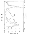
- Figure 4 shows the relationship between the reflectance of light and the colour of the surfaces of the fins of the heat exchanger used for this type of refrigerating cycle.
- B1 denotes the reflectance to the wavelength of a white surface colour of the fins
- B2 denotes the reflectance to the wavelengths of a grey surface colour of the fins
- B3 denotes the reflectance to the wavelength of a black surface colour of the fins.
- the temperature thereof rises to +20 to +100 degrees centigrade as previously mentioned and the wavelength of the heat rays radiated from the surfaces of the fins ranges from 2000 to 20000 angstroms according to the temperature thereof.
- the reflectance becomes lower as the colour of the fins comes closer to black in such a wavelength range.
- the light reflectance of the fins with the black surface is low.
- the present invention enables heat radiation from the surface of the heat exchanger to be remarkably improved.
- the heat exchanger can be made smaller and the cooling or heating capability of the refrigerating cycle can be improved.
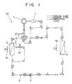
- FIG. 1 shows the refrigerant circuit diagram of an air conditioner AC which can include a heat exchanger of the present invention.
- the air conditioner AC shown in Figure 1 includes a compressor 1, a four-way valve 2, a heat source side heat exchanger 3 serving as an outdoor heat exchanger, a capillary tube 4 serving as an expansion device, a modulator 5 with screen, a user side heat exchanger 6, and an accumulator 7 which are all linked by a refrigerant pipe to provide the refrigerant circuit.
- Blowers 41 and 42 blow air to the heat source side heat exchanger 3 and the user side heat exchanger 6, respectively, to promote heat exchange with the ambient air.
- refrigerant circuit Different refrigerants and oils are sealed in the refrigerant circuit according to the required evaporating temperature of the installation.
- high-temperature equipment such as air conditioner AC in this embodiment uses a sole refrigerant R22 or an HFC-based mixed refrigerant containing R134a, e.g.
- a mixed refrigerant composed of three types namely, R134a, R32 and R125 (the composition of the refrigerant is, for example, 52wt% of R134a, 23 wt% of R32 and 25 wt% of R125), or a mixed refrigerant composed of R32 and R125 (the composition of the refrigerant is, for example 50 wt% of R32 and 50 wt% of R125, or a mixture of the two of approximately the same percentage by weight).
- the oils to be used with the refrigerants are of polyol ester type, alkyl benzene type, or other type which is compatible with the refrigerants.
- R134a has a boiling point of -26 degrees centigrade and a viscosity of 0.204 mPa • S
- R32 has a boiling point of 53 degrees centigrade and a viscosity of 0.140 mPa S
- R125 has a boiling point of -48.3 degrees centigrade and a viscosity of 0.145 mPa • S.
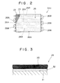
- the heat source side heat exchanger 3 includes a plurality of plate-shaped fins 23, which are spaced at predetermined intervals from each other as illustrated in Figure 2, and a tortuous refrigerant pipe 26 which penetrates the fins 23 in such a manner that it permits heat exchange.
- Each fin 23 is a thin plate 31 which is made of aluminium including an aluminium alloy and is 100 to 120 microns thick.
- the surface of each fin 23 is provided with a rustproof layer 32, which is about two microns thick and formed by immersing the aluminium thin plate 31 in an acid solution (e.g. chromic acid, chromate, bichromate, chromic acid/phosphoric acid, and phosphoric acid).
- an acid solution e.g. chromic acid, chromate, bichromate, chromic acid/phosphoric acid, and phosphoric acid.
- the outer side of the rustproof layer 32 is provided with a coat of a hydrophillic film 35 which is 5 to 10 microns thick.
- the hydrophillic film 35 is provided to make it difficult for water droplets, which lead to circulation resistance, to be formed on the surfaces of the fins 23.
- the hydrophillic film 35 is a mixture of hydrophillic paint, water and a material having properties similar to those of a blackbody.
- the hydrophillic paint is an acrylic resin or hydrophillic organic resin and a silica complex. It is assumed that the blackbody absorbs all light and therefore reflects no light.
- the material which exhibits properties similar to those of the blackbody is selected from carbon black type pigments or cuprous oxides.
- the water is used to ensure easy handling of the paint as it evaporates after painting is finished.
- the paint in this embodiment is prepared by mixing 100 grams of the aforesaid hydrophillic organic resin and silica complex, or acrylic resin, 3000 grams of water, and 5 grams of the carbon black type pigment, that is, 5% of the carbon black type pigment with respect to the hydrophillic paint.
- the fins 23 provided with the rustproof layer 32 are washed, immersed in the aforesaid paint and drawn up, then they are dried and baked to form the hydrophillic film 35 thereon. Since the water evaporates, the mixing ratio need not be very precise.
- the heat exchanging performance of the heat exchanger can be improved if the reflectance of light of the black on the fins 23 is lower than that of B2 shown in Figure 4.
- Holes for inserting the pipe are formed in the fins 23 beforehand and the fins 23 are arranged along a plurality of straight pipes 26A making up the refrigerant pipe 26 at predetermined intervals. Pressure is applied to the inside of the straight pipes 26A to expand them, then bent pipes 26B are welded to them so as to be in communication with the respective straight pipes 26A. Thus, the tortuous refrigerant pipe 26 is configured and the heat exchanger 3 is completed.
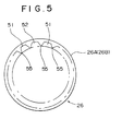
- Figure 5 is the cross-sectional view of the straight pipes 26A (the same view applies to the bent pipes 26B) which form part of the refrigerant pipe 26;
- Figure 6 is a partially enlarged cross-sectional view of Figure 5.
- the inner surface of the straight pipe 26A is provided with, for example, a total of sixty grooves 51.. and 52..; bottom width D of each groove 51 is 0.33mm, for example, and bottom width "e" of each groove 52 is 0.48mm, for example, which is a larger value than D.
- the grooves 51 and 52 are alternately disposed.
- height H of a ridge 55 separating a pair of grooves 51 and 52 is set to 0.3mm, apex angle ⁇ to 30 degrees, and tip curvature r to 0.05mm.
- the twisting angle for helically disposing the grooves 51 and 52 is 18 degrees, for instance.
- the outer diameter OD of the straight pipes 26A is set to e.g. 10mm and the bottom thickness TF thereof is set to e.g. 0.27mm.
- the user side heat exchanger 6 has the same structure as the heat source side heat exchanger 3 so it will not be described here. It should also be noted that the fins are not restricted to the described and illustrated plate shape (the plate-shaped fins are commonly known as plate fins) and that spiral other fin shapes may be used instead.
- the mixed refrigerant flows through the compressor 1, the four-way valve 2, the heat source heat exchanger 3, the capillary tube 4, the modulator 5 with screen, the user side heat exchanger 6, and the accumulator 7.
- the gas refrigerant which is a mixed refrigerant, of high temperature and high pressure discharged from the compressor 1 flows into the heat exchanger 3 which radiates the heat thereof into the ambient air and it condenses.
- the refrigerant is then reduced in pressure through the capillary tube 4 before it flows into the user side heat exchanger 6 and evaporates (endothermic action).
- the heat source side heat exchanger 3 functions as a condenser and the user side heat exchanger 6 functions as a cooler.
- Air is supplied by the blower 41 from outside to the heat source side heat exchanger 3 at a velocity of about 1m/s.
- the warm air resulting from the heat exchange with the heat source side heat exchanger 3 is radiated into the ambient air.
- the fins 23 of the heat source side heat exchanger 3 are provided with the hydrophillic film 35 which is coloured black to exhibit a low reflectance of light, thus enabling remarkably improved heat radiation from the fins 23.
- This makes it possible to reduce the size of the heat source side heat exchanger 3 to secure a required condensing capability.
- the heat exchanger 3 of the same size having this configuration permits improved cooling capability of air conditioner AC owing to its improved condensing capability.
- cool air produced by the heat exchange with the user side heat exchanger 6 is supplied to the user by the blower 42, as previously mentioned, since the fins 23 of the user side heat exchanger 6 are also provided with the hydrophillic film 35 coloured black which exhibits a low reflectance of light, heat absorption from the fins 23 is improved.
- This makes it possible to reduce the size of the user side heat exchanger 6 for a required heat absorbing capability, i.e. cooling capability.
- the heat exchanger 6 of the same size having the aforesaid configuration provides an improved cooling capability for the air conditioner AC owing to its improved heat absorbing capability, i.e. cooling capability.
- the mixed refrigerant flowing into the heat source side heat exchanger 3 and the user side heat exchanger 6 is stirred by the grooves 51 and 52, and when the rate of liquid flow in the refrigerant is low, the mixed refrigerant flowing into the heat source side heat exchanger 3 and the user side heat exchanger 6 helically moves by capillary action along the grooves 51 and 52.
- R32 and R125 have a low viscosity
- R134a has a high viscosity
- R134a with its high viscosity flows primarily through the grooves 52 which are wide
- R32 and R125 flow primarily through the narrow grooves 51.
- the capillary action substantially decreases the circulating resistance of R134a with a consequent decreased pressure loss, thus ensuring smooth flow of the mixed refrigerant to the upper portion in the refrigerant pipe 26 (straight pipes 26A and bent pipes 26B).
- R32 and R125 smoothly flow to the upper portion in the refrigerant pipe 26 along the grooves 51.
- the configuration described above enables the respective ingredient refrigerants to smoothly flow along the grooves 51 or 52 which differ in width to match to the properties, especially the viscosities, of the respective ingredient refrigerants. Therefore, the heat exchange between the refrigerant and the refrigerant pipe 26 takes place over the enlarged or extended area of the inner surface of the refrigerant pipe 26, thus achieving improved heat transfer characteristics. In this case, therefore, the heat radiation, i.e. condensing performance, can be further improved in the heat source side heat exchanger 3, and the heat absorbing characteristic, i.e. cooling characteristic, can be improved also in the user side heat exchanger 6, leading to improved cooling capability of air conditioner AC.
- the heat radiation i.e. condensing performance
- the heat absorbing characteristic i.e. cooling characteristic
- the mixed refrigerant flows through the compressor 1, the four-way valve 2, the user side heat exchanger 6, the modulator 5 with screen, the capillary tube 4, the heat source side heat exchanger 3, and the accumulator 7.
- the gas refrigerant i.e. the mixed refrigerant
- the heat source side heat exchanger 3 functions as the cooler and the user side heat exchanger 6 functions as the condenser.
- air is supplied by the blower 42 to the user side heat exchanger 6.
- the warm air produced by the heat exchange with the user side heat exchanger 6 is circulated to the room where a user is located.
- the fins 23 of the user side heat exchanger 6 are provided with the hydrophillic film 35 coloured black which exhibits low light reflectance thus enabling remarkably improved heat radiation from the fins 23. This makes it possible to reduce the size of the user side heat exchanger 6 for securing a required heating capability. In other words, the user side heat exchanger 6 of the same size having this configuration permits improved heating capability of air conditioner AC.
- the cool air resulting from the heat exchange with the heat source side heat exchanger 3 is radiated outside by the blower 41, as previously mentioned, since the fins 23 of the heat source side heat exchanger 3 are also provided with the hydrophillic film 35 coloured black which exhibits low light reflectance of heat absorption from the fins 23 can be improved.
- This makes it possible to reduce the size of the heat source side heat exchanger 3 for securing a required heat absorbing capability.
- a heat exchanger 3 of the same size having this configuration permits an improved heating capability for air conditioner AC owing to the improved heat absorbing capability.
- the heat transfer characteristic of both heat exchangers 3 and 6 can be improved.
- the heat radiation characteristic i.e. heating performance
- the heat absorbing characteristic can be improved, thereby improving the heating capability of air conditioner AC.
- the operating refrigerant flows through the compressor 1, the four-way valve 2, the user side heat exchanger 6, the modulator 5 with screen, the capillary tube 4, the heat source side heat exchanger 3, the four-way valve 2, and the accumulator 7.
- a solenoid valve 33 is open and therefore, a part of the refrigerant flows through the compressor 1, the solenoid valve 33, and the heat source side heat exchanger 3, thereby defrosting the heat source side heat exchanger 3 while maintaining the heating operation.
- a mixed refrigerant made up from three different refrigerants is used and the grooves of two different widths are formed in the inner surface of the refrigerant pipe.
- the refrigerant may alternatively be a mixture of two types of refrigerants or a mixture of other types of refrigerants.
- the grooves have their widths matched to the properties, especially the viscosities, of the respective refrigerants.
- the air conditioner has been taken as an example in this embodiment, however, the present invention is not limited thereto, the present invention can be effectively applied also to a refrigerator, a cooled showcase, etc.
- the capillary action enables the heat exchange between the refrigerant and the refrigerant pipe to be implemented over a larger area of the inner surface of the pipe while controlling the increase in the pressure loss caused by the circulating resistance of the respective ingredient refrigerants, thus achieving an improved heat transfer characteristic. Furthermore, by utilizing the capillary action based on the groove widths, the difference in the pressure loss caused by the different circulating resistances of the respective ingredient refrigerants is controlled so as to control fluctuations in the mixing ratio of the mixed refrigerant when the mixed refrigerant flows through the refrigerant pipe.
- heat radiation from the surface of the heat exchanger can be significantly improved, therefore, the heat exchanger can be made smaller and also the cooling or heating capability of the refrigerating cycle can be improved.
Landscapes
- Engineering & Computer Science (AREA)
- Physics & Mathematics (AREA)
- Mechanical Engineering (AREA)
- General Engineering & Computer Science (AREA)
- Thermal Sciences (AREA)
- Geometry (AREA)
- Chemical & Material Sciences (AREA)
- Combustion & Propulsion (AREA)
- Heat-Exchange Devices With Radiators And Conduit Assemblies (AREA)
- Other Air-Conditioning Systems (AREA)
Applications Claiming Priority (4)
| Application Number | Priority Date | Filing Date | Title |
|---|---|---|---|
| JP200460/95 | 1995-07-12 | ||
| JP20046095A JPH0926280A (ja) | 1995-07-12 | 1995-07-12 | 内面溝付冷媒配管 |
| JP240877/95 | 1995-08-25 | ||
| JP7240877A JPH0959537A (ja) | 1995-08-25 | 1995-08-25 | 熱交換器用塗料 |
Publications (2)
| Publication Number | Publication Date |
|---|---|
| EP0753709A2 true EP0753709A2 (fr) | 1997-01-15 |
| EP0753709A3 EP0753709A3 (fr) | 1997-09-03 |
Family
ID=26512200
Family Applications (1)
| Application Number | Title | Priority Date | Filing Date |
|---|---|---|---|
| EP96305076A Withdrawn EP0753709A3 (fr) | 1995-07-12 | 1996-07-10 | Echangeur de chaleur pour circuit frigorifique |
Country Status (7)
| Country | Link |
|---|---|
| US (1) | US5862857A (fr) |
| EP (1) | EP0753709A3 (fr) |
| KR (1) | KR100417844B1 (fr) |
| CN (1) | CN1143119C (fr) |
| CA (1) | CA2179448A1 (fr) |
| MY (1) | MY116659A (fr) |
| SG (1) | SG44961A1 (fr) |
Cited By (3)
| Publication number | Priority date | Publication date | Assignee | Title |
|---|---|---|---|---|
| EP1202018A3 (fr) * | 2000-10-27 | 2004-04-07 | Alcoa Inc. | Surface microtexturée d'échange de chaleur |
| EP2077429A4 (fr) * | 2006-10-18 | 2014-05-07 | Daikin Ind Ltd | Échangeur de chaleur et dispositif de réfrigération |
| CN119412843A (zh) * | 2024-12-12 | 2025-02-11 | 山东沐阳新能源有限公司 | 一种空气能热泵一体机及其使用方法 |
Families Citing this family (24)
| Publication number | Priority date | Publication date | Assignee | Title |
|---|---|---|---|---|
| JP2001241877A (ja) * | 2000-02-25 | 2001-09-07 | Furukawa Electric Co Ltd:The | 内面溝付管及びその製造方法 |
| JP4822238B2 (ja) * | 2001-07-24 | 2011-11-24 | 株式会社日本製鋼所 | 液媒用内面溝付伝熱管とその伝熱管を用いた熱交換器 |
| KR20030048921A (ko) * | 2001-12-13 | 2003-06-25 | 주식회사 엘지이아이 | 공기조화기의 열교환기 및 그 제조방법 |
| US8573022B2 (en) * | 2002-06-10 | 2013-11-05 | Wieland-Werke Ag | Method for making enhanced heat transfer surfaces |
| US7311137B2 (en) * | 2002-06-10 | 2007-12-25 | Wolverine Tube, Inc. | Heat transfer tube including enhanced heat transfer surfaces |
| BRPI0305057B1 (pt) * | 2002-06-10 | 2015-07-14 | Wolverine Tube Inc | Tubo de transferência de calor, ferramenta para cortar a superfície interna de um tubo e método para a produção de um tubo |
| US20060112535A1 (en) | 2004-05-13 | 2006-06-01 | Petur Thors | Retractable finning tool and method of using |
| CN2784853Y (zh) * | 2004-12-29 | 2006-05-31 | 鸿富锦精密工业(深圳)有限公司 | 热管 |
| CA2601112C (fr) * | 2005-03-25 | 2011-12-13 | Wolverine Tube, Inc. | Outil servant a realiser des surfaces de transfert thermique ameliorees |
| CN100458346C (zh) * | 2005-12-16 | 2009-02-04 | 金龙精密铜管集团股份有限公司 | 一种溴冷机组蒸发器用铜蒸发换热管 |
| CN100451530C (zh) * | 2005-12-16 | 2009-01-14 | 金龙精密铜管集团股份有限公司 | 一种溴冷机组冷凝器用铜热交换管 |
| JP5446163B2 (ja) * | 2008-08-04 | 2014-03-19 | ダイキン工業株式会社 | 熱交換器用溝付き管 |
| US8613308B2 (en) | 2010-12-10 | 2013-12-24 | Uop Llc | Process for transferring heat or modifying a tube in a heat exchanger |
| CN103339460B (zh) * | 2011-01-28 | 2017-01-18 | 开利公司 | 用于换热器的载流管 |
| WO2013094084A1 (fr) * | 2011-12-19 | 2013-06-27 | 三菱電機株式会社 | Climatiseur |
| US20150219401A1 (en) * | 2012-01-18 | 2015-08-06 | Shanghai Dazhi Heat Dissipation Technology Co., Ltd. | Heat-wing |
| CN103591820A (zh) * | 2013-11-26 | 2014-02-19 | 昆山德泰新材料科技有限公司 | 一种换热管 |
| CN104875314B (zh) * | 2014-02-27 | 2019-03-29 | 靳宏杰 | 一种塑铝复合散热器铝合金型材管道内有翅片的塑铝复合方法 |
| US10446995B2 (en) | 2014-10-17 | 2019-10-15 | Moog Inc. | Superconducting devices, such as slip-rings and homopolar motors/generators |
| CN109974332B (zh) * | 2017-12-27 | 2024-01-16 | 宁波方太厨具有限公司 | 一种水冷型半导体制冷装置 |
| CN109974334B (zh) * | 2017-12-27 | 2024-01-16 | 宁波方太厨具有限公司 | 一种风冷型半导体制冷装置 |
| JP6868146B1 (ja) * | 2020-06-29 | 2021-05-12 | 株式会社クボタ | 流体撹拌要素を具える熱分解管 |
| CN114152136A (zh) * | 2021-12-13 | 2022-03-08 | 江阴博圣热能科技有限公司 | 一种不锈钢焊接麻面管及其加工工艺 |
| CN114126383B (zh) * | 2021-12-21 | 2025-02-18 | 珠海格力电器股份有限公司 | 散热系统、变频柜和电器设备 |
Family Cites Families (21)
| Publication number | Priority date | Publication date | Assignee | Title |
|---|---|---|---|---|
| JPS55164264A (en) * | 1979-06-08 | 1980-12-20 | Hitachi Ltd | Aqueous coating composition and heat exchanger coated with it |
| JPS56117097A (en) * | 1980-02-20 | 1981-09-14 | Hitachi Ltd | Heat transferring pipe |
| JPS57175896A (en) * | 1981-04-24 | 1982-10-28 | Hitachi Ltd | Heat transmission pipe |
| JPS5883190A (ja) * | 1981-11-12 | 1983-05-18 | Matsushita Electric Ind Co Ltd | 熱交換器 |
| JPS58208593A (ja) * | 1982-05-27 | 1983-12-05 | Sanyo Electric Co Ltd | 熱交換器の親水処理方法 |
| US4705103A (en) * | 1986-07-02 | 1987-11-10 | Carrier Corporation | Internally enhanced tubes |
| JPS63113258A (ja) * | 1986-10-30 | 1988-05-18 | 松下電器産業株式会社 | 非共沸混合冷媒用気液接触器 |
| JPS63172893A (ja) * | 1987-01-12 | 1988-07-16 | Matsushita Refrig Co | 内面溝付伝熱管 |
| EP0288258A3 (fr) * | 1987-04-24 | 1989-03-08 | Alcan International Limited | Procédé pour rendre hydrophiles des surfaces métalliques et produits ainsi obtenus |
| US4926650A (en) * | 1988-05-18 | 1990-05-22 | Pennwalt Corporation | Refrigerant fluid and method of use |
| JPH0297896A (ja) * | 1988-09-30 | 1990-04-10 | Matsushita Refrig Co Ltd | 熱交換器の製造方法 |
| SU1677481A1 (ru) * | 1988-10-17 | 1991-09-15 | Производственное Объединение "Белгородский Завод Энергетического Машиностроения" | Теплообменна труба |
| US5470431A (en) * | 1990-08-20 | 1995-11-28 | Showa Aluminum Corp. | Stack type evaporator |
| JP2701956B2 (ja) * | 1990-02-13 | 1998-01-21 | 三菱伸銅株式会社 | 伝熱用電縫管 |
| US5052476A (en) * | 1990-02-13 | 1991-10-01 | 501 Mitsubishi Shindoh Co., Ltd. | Heat transfer tubes and method for manufacturing |
| US5137067A (en) * | 1991-12-16 | 1992-08-11 | Jw Aluminum Company | Hydrophilic and corrosion resistant fins for a heat exchanger |
| JPH06147532A (ja) * | 1992-11-12 | 1994-05-27 | Matsushita Refrig Co Ltd | 空気調和機 |
| US5514478A (en) * | 1993-09-29 | 1996-05-07 | Alcan International Limited | Nonabrasive, corrosion resistant, hydrophilic coatings for aluminum surfaces, methods of application, and articles coated therewith |
| US5510010A (en) * | 1994-03-01 | 1996-04-23 | Carrier Corporation | Copper article with protective coating |
| US5562949A (en) * | 1994-03-16 | 1996-10-08 | United Technologies Corporation | Low solids hydrophilic coating |
| US5545438A (en) * | 1995-03-22 | 1996-08-13 | Betz Laboratories, Inc. | Hydrophilic treatment for aluminum |
-
1996
- 1996-06-19 CA CA002179448A patent/CA2179448A1/fr not_active Abandoned
- 1996-07-03 MY MYPI96002721A patent/MY116659A/en unknown
- 1996-07-04 SG SG1996010210A patent/SG44961A1/en unknown
- 1996-07-08 KR KR1019960027458A patent/KR100417844B1/ko not_active Expired - Fee Related
- 1996-07-10 EP EP96305076A patent/EP0753709A3/fr not_active Withdrawn
- 1996-07-11 US US08/680,264 patent/US5862857A/en not_active Expired - Lifetime
- 1996-07-12 CN CNB961099151A patent/CN1143119C/zh not_active Expired - Fee Related
Cited By (4)
| Publication number | Priority date | Publication date | Assignee | Title |
|---|---|---|---|---|
| EP1202018A3 (fr) * | 2000-10-27 | 2004-04-07 | Alcoa Inc. | Surface microtexturée d'échange de chaleur |
| US6925711B2 (en) | 2000-10-27 | 2005-08-09 | Alcoa Inc. | Micro-textured heat transfer surfaces |
| EP2077429A4 (fr) * | 2006-10-18 | 2014-05-07 | Daikin Ind Ltd | Échangeur de chaleur et dispositif de réfrigération |
| CN119412843A (zh) * | 2024-12-12 | 2025-02-11 | 山东沐阳新能源有限公司 | 一种空气能热泵一体机及其使用方法 |
Also Published As
| Publication number | Publication date |
|---|---|
| CA2179448A1 (fr) | 1997-01-13 |
| MY116659A (en) | 2004-03-31 |
| EP0753709A3 (fr) | 1997-09-03 |
| KR970007280A (ko) | 1997-02-21 |
| CN1143119C (zh) | 2004-03-24 |
| KR100417844B1 (ko) | 2004-06-05 |
| US5862857A (en) | 1999-01-26 |
| CN1148686A (zh) | 1997-04-30 |
| SG44961A1 (en) | 1997-12-19 |
Similar Documents
| Publication | Publication Date | Title |
|---|---|---|
| US5862857A (en) | Heat exchanger for refrigerating cycle | |
| AU2011100257A4 (en) | Heat exchanger and heat pump device using same | |
| KR0142506B1 (ko) | 비공비혼합 냉매를 채용한 공기 조화기 | |
| Ito et al. | Boiling heat transfer and pressure drop in internal spiral-grooved tubes | |
| WO2018047416A1 (fr) | Climatiseur | |
| MY130596A (en) | Heat transfer tube for zeotropic refrigerant mixture, heat exchanger with the heat transfer tubes, method of assembling the heat exchanger, and refrigerator and air conditioner with the heat exchangers | |
| KR20150029728A (ko) | 공기 조화기용 서펜타인 열교환기 | |
| EP3379192A1 (fr) | Ailette à pré-revêtement et échangeur de chaleur | |
| EP3438593A1 (fr) | Matériau d'ailette pour échangeur de chaleur, et échangeur de chaleur | |
| JPH0959537A (ja) | 熱交換器用塗料 | |
| EP4083558B1 (fr) | Échangeur de chaleur et dispositif à cycle frigorifique | |
| JPH0926289A (ja) | 熱交換器及びそれを搭載した電気機器 | |
| JPH0926280A (ja) | 内面溝付冷媒配管 | |
| CN215951587U (zh) | 换热器及空调器 | |
| CN117781516A (zh) | 热交换器 | |
| WO2010038403A1 (fr) | Dispositif de climatisation | |
| JPH11264630A (ja) | 空気調和機 | |
| JP2997189B2 (ja) | 凝縮促進型内面溝付伝熱管 | |
| CN113566311A (zh) | 换热器及空调器 | |
| JPH08145490A (ja) | ヒートポンプエアコン用熱交換器 | |
| JP3421130B2 (ja) | 空気調和機 | |
| JP3349265B2 (ja) | 熱交換器 | |
| KR20050023759A (ko) | 착상 지연용 열교환기 | |
| TW297090B (fr) | ||
| JP3199621B2 (ja) | 混合冷媒を使用する内面溝付伝熱管 |
Legal Events
| Date | Code | Title | Description |
|---|---|---|---|
| PUAI | Public reference made under article 153(3) epc to a published international application that has entered the european phase |
Free format text: ORIGINAL CODE: 0009012 |
|
| AK | Designated contracting states |
Kind code of ref document: A2 Designated state(s): DE FR GB IT |
|
| PUAL | Search report despatched |
Free format text: ORIGINAL CODE: 0009013 |
|
| AK | Designated contracting states |
Kind code of ref document: A3 Designated state(s): DE FR GB IT |
|
| 17P | Request for examination filed |
Effective date: 19971024 |
|
| STAA | Information on the status of an ep patent application or granted ep patent |
Free format text: STATUS: THE APPLICATION HAS BEEN WITHDRAWN |
|
| 18W | Application withdrawn |
Withdrawal date: 19990617 |