EP0754594A2 - Rideau écran avec sécurité élevée en cas d'accident - Google Patents
Rideau écran avec sécurité élevée en cas d'accident Download PDFInfo
- Publication number
- EP0754594A2 EP0754594A2 EP96111526A EP96111526A EP0754594A2 EP 0754594 A2 EP0754594 A2 EP 0754594A2 EP 96111526 A EP96111526 A EP 96111526A EP 96111526 A EP96111526 A EP 96111526A EP 0754594 A2 EP0754594 A2 EP 0754594A2
- Authority
- EP
- European Patent Office
- Prior art keywords
- anchoring
- housing
- cover device
- locking
- cover
- Prior art date
- Legal status (The legal status is an assumption and is not a legal conclusion. Google has not performed a legal analysis and makes no representation as to the accuracy of the status listed.)
- Granted
Links
Images





Classifications
-
- B—PERFORMING OPERATIONS; TRANSPORTING
- B60—VEHICLES IN GENERAL
- B60R—VEHICLES, VEHICLE FITTINGS, OR VEHICLE PARTS, NOT OTHERWISE PROVIDED FOR
- B60R5/00—Compartments within vehicle body primarily intended or sufficiently spacious for trunks, suit-cases, or the like
- B60R5/04—Compartments within vehicle body primarily intended or sufficiently spacious for trunks, suit-cases, or the like arranged at rear of vehicle
- B60R5/044—Compartments within vehicle body primarily intended or sufficiently spacious for trunks, suit-cases, or the like arranged at rear of vehicle luggage covering means, e.g. parcel shelves
- B60R5/045—Compartments within vehicle body primarily intended or sufficiently spacious for trunks, suit-cases, or the like arranged at rear of vehicle luggage covering means, e.g. parcel shelves collapsible or transformable
- B60R5/047—Compartments within vehicle body primarily intended or sufficiently spacious for trunks, suit-cases, or the like arranged at rear of vehicle luggage covering means, e.g. parcel shelves collapsible or transformable collapsible by rolling-up
-
- B—PERFORMING OPERATIONS; TRANSPORTING
- B60—VEHICLES IN GENERAL
- B60R—VEHICLES, VEHICLE FITTINGS, OR VEHICLE PARTS, NOT OTHERWISE PROVIDED FOR
- B60R21/00—Arrangements or fittings on vehicles for protecting or preventing injuries to occupants or pedestrians in case of accidents or other traffic risks
- B60R21/02—Occupant safety arrangements or fittings, e.g. crash pads
- B60R21/06—Safety nets, transparent sheets, curtains, or the like, e.g. between occupants and glass
Definitions
- roller blinds In order to cover the loading space of station wagons and thus to prevent an insight into the loading space, it is known for example from DE-A-44 05 280 to use roller blinds.
- This known roller blind has an elongated housing in which a winding shaft is rotatably mounted.
- a roller blind web is attached at one end to this winding shaft and can be pulled out of the housing through a slot in the housing.
- a spring motor is connected to the winding shaft, which serves to wind the roller blind again onto the winding shaft if the cover roller blind is not intended to cover the access opening.
- the housing itself consists of an approximately cylindrical part, at the ends of which end caps are fitted, in which locking members are movably mounted. With these end caps, the cover roller blind sits in corresponding pockets, which are provided on the body side behind the erected backrest of the station wagon. This makes it possible to completely remove the cover roller blind from the vehicle if, for example, the entire loading space is required and for this purpose the rear seat back is at least folded down.
- the well-known cover roller blind not only prevents the view of the part of the cargo space that is below the extended cover roller blind, but it also provides a certain safety function in the event of a frontal impact. Parts in the cargo area are thrown forward in the direction of the passenger compartment in the event of a frontal impact. In unfavorable circumstances, however, they are not held back by the back seat back, but climb up on inclined surfaces, thereby overcoming the back seat back and flying against the head of the passengers from behind.
- the extended cover anchored in the vicinity of the tailgate prevents such climbing and thus largely holds back the parts in the cargo hold.
- the conditions are much less favorable if the loading height in the loading space exceeds the upper edge of the rear seat backrest.
- a safety net is used to secure the passenger compartment, which begins at the upper edge of the rear seat back and extends to just under the headlining. The forces that occur in the safety net are so great that the anchoring devices, as they are known for roller blinds, would not be sufficient.
- arm-shaped or peg-shaped anchoring members that extend parallel to the direction of travel in connection with corresponding anchoring openings ensure a very high level of safety in the event of rear-end collisions.
- the new connection between the body and the housing of the cover device cannot come off even if the body should widen laterally in the event of a collision in the area of the housing of the cover device.
- the locking devices are released when the body is expanded. This cannot happen with the new solution with arms or pins engaging in corresponding openings.
- pins aligned essentially parallel to the direction of travel are aligned essentially parallel to the direction of travel.
- the new arrangement is suitable both for pure roller blinds and for housings in which safety nets are housed, which extend from the housing to the headlining when in use, and finally for applications in which both a safety net and in the housing a roller blind are housed, which can be brought into their functional position depending on the loading condition of the load space.
- the anchoring opening measured in the longitudinal direction of the housing, has a greater width than the respective anchoring element, measured in same direction. Regardless of the dimensions of the body, the housing can be easily pushed onto the anchoring members or, conversely, the housing with the anchoring members can be inserted into the openings.
- the anchoring openings are formed by a slot running through the length of the housing.
- this slot is preferably the slot of a continuous groove over the length of the housing.
- the width of this groove is adapted to the thickness of the pin.
- the peg-shaped anchoring links are advantageously each delimited by straight surfaces, the generatrix of which lies parallel to the longitudinal extent of the housing. In the case of transverse loading, the deformation forces which are effective at the contact points between the anchoring members and the anchoring openings are significantly reduced because of the flat system.
- the production of the housing becomes very cost-saving if that part is formed by a section of an extruded profile which contains the groove which forms the receiving opening.
- the luggage parts of the cargo space flying around introduce forces into the housing of the covering device which are directed upwards or obliquely upwards at the front. Therefore, it is particularly advantageous if the anchoring members are aligned approximately horizontally, because they can then absorb a very large force.
- the locking members are expediently pivotally mounted, namely they are located outside the housing, which can be kept relatively small. Its outer dimensions are then only slightly larger than the winding of the safety net or the cover blind on the winding shaft or the winding shafts. An additional space for accommodating the locking members is not required, while on the other hand there is sufficient space in the body for accommodating the locking members without these appearing in a disruptive manner.
- a particularly expedient place for the attachment and storage of the locking members is in the area of the anchoring members, namely among them. If the bearing for the locking member is located under the free end of the anchoring member, one is created Self-locking locking force that holds the housing on the anchoring members without the need for particularly strong pretensioning forces that pretension the locking members into the engaged position with the housing in the idle state.
- the locking effect can be achieved very simply in that there is a rib on a relevant underside of the housing, which cooperates with the locking member. This rib also extends over the entire length of the housing if it is made from a section of an extruded profile.
- the assembly is facilitated if the storage means for the locking member and the anchoring member are made in one piece.
- the storage means for the locking member and the anchoring member are made in one piece.
- an actuating surface is provided on the locking member, which protrudes laterally beyond the anchoring member.
- An actuating element interacts with this actuating surface and is preferably mounted in the housing.
- This actuator can be an actuator slide, which is located in front of and next to the anchoring opening, so that the extruded profile that forms the housing is not impaired in its strength by openings that would serve to accommodate the actuator.
- a second set of anchoring members or anchoring openings can be provided on the housing.
- This second set makes it possible to accommodate the new cover device in the footwell of the station wagon so that the safety net can also be used if the loading volume is to be increased the rear seat back is at least folded forward. If the cover device were to remain in the area of the upper edge of the rear seat backrest erected, the housing would run across the loading space and significantly impair the loading possibility. This disadvantage is avoided by the possibility of anchoring the housing in the footwell.
- Very simple anchoring members of the second set are, for example, mushroom-shaped anchoring members which interact with an appropriately designed T-slot.
- This T-groove forms the receiving openings of the second set and can expediently be designed as a straight continuous groove below the front edge of the rear seat.
- the housing with the safety net can be inserted into the groove through an open rear door with the mushroom-like anchoring members.
- the rear area 1 shows a broken-open rear area 1 of a station wagon, approximately from a viewing direction corresponding to the broken-away left rear corner.
- the rear area 1 which forms a loading space, has a base 2 and two side walls 3 which are mirror images of one another and spaced apart from one another, of which only one can be seen due to the broken-open representation.
- the side wall 3 contains two rear side windows 4 and 5, which are separated from one another by a C-pillar 6.
- a roof 7 with a roof liner 8 pointing to the interior of the vehicle is stretched over the two side walls 3.
- a rear opening of the vehicle which is no longer recognizable in the figure, can be closed by means of a corresponding tailgate or tailgate.
- a covering and separating device 12 is provided for separating the cargo space located in the rear area 1 from the passenger compartment or for covering the cargo space in the rear area.
- This has an elongated housing 13 from which a cover roller blind 14 and a safety net 15 can optionally be pulled out.
- the housing 13 extends approximately at the level of the upper edge of the rear seat back 9 essentially between the two side walls 3.
- the cover roller blind 14 consists of an opaque, flexible and closed film web, which is provided on its free edge with an anchoring strut 16 which extends over the width and over which a cover flap 17 with a grip hole 18 protrudes towards the rear. With the help of the strut 16 projecting on both sides, the extended cover roller blind 15 can be anchored in holders not shown, so that it tightens the lower one Half of the load space spanned between the rear seat back 9 and the tailgate.
- the cover roller blind 14 extends approximately at the level of the lower edges of the side windows 4 and 5 and approximately parallel to the floor 2.
- the safety net 15 has on its free edge a sewn-on loop 19 through which a holding strut 21 runs.
- the holding strut 21 is a tube in which two holding members 22 are inserted, which carry disc-shaped heads 23 at their ends. These disk-shaped heads 23 can be inserted into T-shaped pockets 24, which are located just below the roof lining 8 in the vicinity of the two side walls 3. In this way, the safety net 15 is kept taut, in such a way that its free edge formed by the loop 19 runs just below the roof lining 8.
- the type of anchoring of the housing 13 of the covering device 12 is illustrated in a highly schematic manner in FIG. 2, the body parts being omitted in order to recognize the essentials.
- the two receiving pockets 25 are each delimited by a rear wall 26, a bottom surface 27 and a side wall 28.
- the housing 13 has a complementary design at its ends 29 so that it fits into the receiving pockets 25.
- two anchoring pins 31 with a rectangular cross-section extend into the receiving pockets 25 and protrude from the rear wall 26 into the respective receiving pocket 25, and approximately parallel to the floor surface 27. Relative to the vehicle in which the receiving pockets 25 are located, the anchoring pins 31 point with their longitudinal axis parallel to the direction of travel, their free ends 32 pointing towards the rear end of the vehicle.
- the anchoring pins 31 cooperate with anchoring openings 33, which are located in a rear surface 34 of the housing 13 facing the rear seat back 9 near its underside 35, as can be seen in FIG. 3.
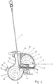
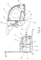
- FIG. 4 shows a section along line IV according to FIG. 2, while FIGS. 5 and 6 illustrate sections in the area of lines VV from FIG. 2 .
- the extruded profile 36 viewed in cross section, is delimited by three main sections 38, 39 and 41.
- the section 39 is essentially flat and forms the rear surface 34
- the section 41 is also essentially flat and forms the underside 35
- the section 38 is curved in a quarter circle, which, viewed in cross section, gives the profile of a quarter bar.
- Sections 38 and 41 merge integrally into section 39, while at the transition point between section 41 and section 38 a cloth slit 42 is formed, which forms the access opening to a chamber 43 delimited by sections 38, 39 and 41.
- a winding shaft 44 is rotatably mounted, on which the cover roller blind 14 can be wound and on which it is fastened with an edge.
- the winding shaft 44 is supported in a known manner on bearings which are present in end pieces 45, which are plugged onto the free ends of the extruded profile section 36 and surround them to a certain extent on their outer peripheral surface with their cup-shaped edge 46.
- the extruded profile section 37 seen in the longitudinal direction of the housing 13, has a significantly shorter extension than the extruded profile section 36, so that the latter projects beyond the end 37 over the section 37, as can be seen in FIG. 3.
- Section 37 has an area 47 surrounding a partially cylindrical chamber 46, which merges into a shoulder surface 48 on the one hand and into a rising wall 49 on the other hand.
- An essentially smooth wall 51 adjoins the shoulder surface 48 and runs parallel and at a distance from the wall 49.
- a winding shaft 52 is rotatably mounted, on which the safety net 14 is fastened with one edge.
- the winding shaft 52 like the winding shaft 44, is prestressed in the winding direction of the safety net 15 with the aid of a respectively assigned spring motor, not shown, so that the winding shaft 52 endeavors to wind the safety net 15 and pull it into the housing 13.
- the safety net 15 leads, starting from the winding shaft 52, through the gap formed between the two walls 51 and 49 to the outside.
- a groove 54 is formed, the slot 55 of which forms the anchoring opening 33 in addition to the end caps 45.
- One wall of the groove 54 is the portion 41 forming the bottom, while the other wall is a wall 56 projecting into the chamber 43. As can be seen in FIG. 6, the wall 56 runs below the winding shaft 44 or the winding of the cover roller blind 14 formed thereon.
- the bottom portion 41 is profiled to form a locking groove 57, so that a locking shoulder 58 is formed which is directed obliquely downwards.
- the locking shoulder 58 is part of a locking rib 59 pointing downward.
- the locking groove 57 leads to the formation of an inwardly projecting rib, the apex 61 of which lies at the same height as a contact surface 62, which is located inside the groove 54 at the end opposite the slot 55.
- the edge 46 of the end caps 45 is extended in the region of the rear surface 34 in the direction of the extruded profile section 37, which is the housing for the safety net 15, thereby creating a wall 63 which runs parallel to the rear surface 34 and is parallel and at a distance from the rear surface 34 runs.
- an actuating member 64 is guided so as to be vertically displaceable, which is biased downwards to be resilient by means of a compression spring 65, which is supported on an arm 66 of the wall 63.
- the anchoring pin 31 is also a section of an extruded profile made of aluminum, which, viewed in cross section, is approximately U-shaped.
- the locking pin 31 is from a flat bottom 68 and one as well straight upper side 69, which, starting from the free end 32 of the anchoring pin 31, merges via an inclined surface 71 into a further surface 72 parallel to the lower side 68.
- Two spaced apart and mutually parallel webs 73 and 74 connect the anchoring pin to a lower fastening and holding plate 75, which integrally carries a bearing part 76 projecting upwards at its front free end.
- This bearing part 76 contains an approximately three-quarter circular cylindrical groove 77 which is open towards the web 74 and serves as a pivot bearing for the locking member 67.
- the anchoring pin 31 is fastened in the body, for example on a bracket 78 shown in FIG. 6.
- the locking member 67 is a plastic molding with an approximately rectangular shape in plan view. It consists of a hinge tab 78 which carries a cylindrical bead 79 at its free end. The bead 79 is designed such that it can be rotated in the groove 77 and can only be inserted into the groove 77 in its longitudinal direction by means of an axial movement.
- the hinge tab 78 merges into a rectangular block 81 which projects obliquely upwards and forms a latching lug 82 with a latching surface 83 adjoining it.
- An extension 84 which is designed as a plane-parallel plate and runs approximately parallel to the hinge bracket 78, adjoins the lower end of the latching surface 83.
- the width of the hinge bracket 78, the cuboid block 81 and the extension 84, each measured in the same direction, corresponds approximately to the width of the anchoring pin 31, measured in the direction parallel to the longitudinal extension of the groove 77.
- a block 85 is formed on the side surface of the extension 84 facing the viewer, the upper side of which forms an actuating surface 86.
- An extension 87 interacts with this actuating surface 86 and is an integral component of the actuating member 64 which projects downwards.
- the actuating member 64 projects upward beyond the housing 13 with an actuating surface 87 which can be operated by hand.
- the part of the anchoring pin 31 projecting into the receiving pocket 25 is provided with a plastic cladding 89 which projects into the mouth formed between the anchoring pin 31 and the fastening plate 75 and forms the lower bottom surface 27 of the receiving pocket 25 and its rear wall 26.
- the housing 13 lies in the receiving pockets 25, the anchoring pins 31 projecting there protrude through the anchoring openings 33 into the groove 54.
- the contour of the anchoring pin 31 provided with the cladding 89 is adapted to the contour of the wall 56 of the groove 54, while the flat underside is in contact with the wall section 62 and the nose 61.
- the anchoring pin 31 has only a very slight height play in the groove 54.
- the anchoring pin 31 extends from the cup-shaped edge 46 of the relevant end cap 45 to almost the actuating extension 87 of the actuating member 64.
- the lateral play of the anchoring pin 31 between the above-mentioned components is just so great that body tolerances are still compensated for.
- the actuation extension 87 is aligned with the actuation surface 86 opposite it.
- the locking member 67 which is pivotally mounted in the groove 77, engages with its latching lug 82 in the latching groove 57 from below, the latching surface 83 abutting against the latching surface 58 of the housing 13. In this position, the locking member 67 is held by a coil spring 91, which acts from the bottom against the extension 84, and the force of this compression spring 91 is greater than the force of the spring 65, so that the locking position between the two locking surfaces 58 and 83 is not can be released from the spring 65, which tends to push the actuator 64 down.
- the user can pull the cover roller blind 14 or the safety net 15 out of the housing 13 and anchor it at the correspondingly provided body positions. If, in the event of a rear-end collision, parts located in the loading space are flung against the open safety net 15, the forces which occur are absorbed on the one hand by the suspension of the holding members 22 in the receiving pockets 24 and on the other hand via the winding shaft 52 in the housing section 37 and from there to the housing section 36 transferred, which is held by means of the groove 54 on the anchoring pin 31.
- the anchoring pins 31 are able to absorb relatively large forces which are directed transversely to their longitudinal extension, that is to say upwards, without the risk that the connection between the anchoring pins 31 and the housing 13 is lost.
- the covering roller blind 14 and the safety net 15 are first released from their anchors on the body side, so that they can wind up on the associated winding shaft 44 or 52. Then the actuating members 64 projecting upwards above the housing 13 are pressed down by hand at both end ends of the housing 13, which leads to the locking members 67 being counteracting the action the spring 91 pivot down to bring the locking lug 82 out of the locking groove 57. Then the housing 13 with the covering roller blind wound thereon and the safety net 15 can be removed to the rear from the rear area 1 in order to have the full loading space available.
- the cover device 12 is inserted in the reverse direction, an inclined surface 90 provided on the extension 87 ensuring that the actuating member 64 is lifted upward against the action of the spring 65 when it slides onto the actuating surface 86.
- FIG. 9 A development of the covering device 12 is schematically illustrated in FIG. 9, the safety net 15 of which can also be used when the rear seat back 9 is folded forward onto its associated rear seat 92.
- two or more mushroom-shaped anchoring members 93 are provided on the housing section 37, which bear an essentially cylindrical shaft 94 and a disk-shaped head 95 seated on the shaft.
- Anchoring members 93 are attached to shaft 94, as shown in FIG. 4.
- a rail 96 with a T-shaped groove 97 is attached in the footwell and is accessible through the rear doors.
- the cross section of the T-shaped groove 97 is adapted to the lateral profile of the mushroom-shaped anchoring members 93. If the entire loading space is required, the housing 13 removed from the receiving pockets 25 is inserted into the footwell through the opened rear door, the mushroom-shaped anchoring members 93 being threaded into the T-groove 95 and positively connecting the housing 13 to the rail 94.
- the housing 13 is now again transverse to the longitudinal axis of the vehicle, but in the footwell, and the extended safety net 15 can in turn be fastened in a known manner under the headlining.
- a cover device has a housing to be fastened in a vehicle, in which two winding shafts are located.
- a cover roller blind is connected to one winding shaft, while a safety net can be wound onto the other winding shaft. If necessary, the housing can be removed from the vehicle, the anchorage for the housing being designed in such a way that it is able to absorb those forces which occur when loose parts are released from the load space of the motor vehicle against the open safety net in a frontal impact to be flung.
Landscapes
- Engineering & Computer Science (AREA)
- Mechanical Engineering (AREA)
- Vehicle Step Arrangements And Article Storage (AREA)
- Footwear And Its Accessory, Manufacturing Method And Apparatuses (AREA)
- Body Structure For Vehicles (AREA)
Applications Claiming Priority (2)
| Application Number | Priority Date | Filing Date | Title |
|---|---|---|---|
| DE19526666A DE19526666C2 (de) | 1995-07-21 | 1995-07-21 | Abdeckeinrichtung mit hoher Crashsicherheit |
| DE19526666 | 1995-07-21 |
Publications (3)
| Publication Number | Publication Date |
|---|---|
| EP0754594A2 true EP0754594A2 (fr) | 1997-01-22 |
| EP0754594A3 EP0754594A3 (fr) | 1999-12-22 |
| EP0754594B1 EP0754594B1 (fr) | 2003-01-08 |
Family
ID=7767431
Family Applications (1)
| Application Number | Title | Priority Date | Filing Date |
|---|---|---|---|
| EP96111526A Expired - Lifetime EP0754594B1 (fr) | 1995-07-21 | 1996-07-17 | Rideau écran avec sécurité élevée en cas d'accident |
Country Status (3)
| Country | Link |
|---|---|
| EP (1) | EP0754594B1 (fr) |
| DE (2) | DE19526666C2 (fr) |
| ES (1) | ES2189843T3 (fr) |
Cited By (11)
| Publication number | Priority date | Publication date | Assignee | Title |
|---|---|---|---|---|
| EP0861757A1 (fr) * | 1997-02-26 | 1998-09-02 | PETER BUTZ GmbH & Co Verwaltungs-KG | Dispositif de séparation d'un compartiment à bagages pour véhicules automobiles, en particulier pour breaks |
| EP1304265A3 (fr) * | 2001-10-19 | 2003-08-20 | Dr.Ing. h.c.F. Porsche Aktiengesellschaft | Volet cache-bagages |
| EP1484221A3 (fr) * | 2003-06-02 | 2005-03-23 | BOS GmbH & Co. KG | Dispositif de maintien d'un appareil fonctionnel dans un intérieur véhicule |
| EP1541418A1 (fr) * | 2003-12-12 | 2005-06-15 | Renault s.a.s. | Véhicule automobile comprenant un système de rangement d'un tendelet |
| EP1741600A1 (fr) * | 2005-07-08 | 2007-01-10 | BOS GmbH & Co. KG | Dispositif de protection pour un coffre d'un véhicule automobile |
| EP1775164A1 (fr) * | 2005-10-14 | 2007-04-18 | BOS GmbH & Co. KG | Dispositif de sécurité avec des pièces d'adaptation échangeables |
| EP1844984A3 (fr) * | 2006-04-11 | 2008-01-23 | BOS GmbH & Co. KG | Espace de chargement pour un véhicule automobile doté d'un dispositif de protection |
| US7392834B2 (en) | 2005-10-14 | 2008-07-01 | Bos Gmbh & Co. Kg | Protection device with replaceable adaptor parts |
| EP1932722A3 (fr) * | 2006-12-15 | 2010-03-17 | BOS GmbH & Co. KG | Agencement de store |
| GB2469681A (en) * | 2009-04-24 | 2010-10-27 | Bentley Motors Ltd | Retention device for a vehicle luggage compartment |
| FR2989942A1 (fr) * | 2012-04-30 | 2013-11-01 | Renault Sa | Systeme de verrouillage d'une patte d'ancrage d'un organe amovible, notamment d'un tendelet pour vehicule, et vehicule correspondant |
Families Citing this family (9)
| Publication number | Priority date | Publication date | Assignee | Title |
|---|---|---|---|---|
| DE19811886B4 (de) * | 1998-03-18 | 2007-08-16 | Bayerische Motoren Werke Ag | Rücksitz oder Rücksitzbank eines Personenkraftwagens |
| DE10063465A1 (de) | 2000-12-19 | 2002-06-27 | Butz Peter Verwaltung | Vorrichtung zur Aufnahme einer flexiblen, insbesondere von einer Wickelwelle entgegen der Wirkung eines Federmotors abziehbaren Werkstoffbahn einer Kfz-Sicherheitseinrichtung |
| DE10063466A1 (de) | 2000-12-19 | 2002-06-27 | Butz Peter Verwaltung | Vorrichtung zur Aufnahme einer flexiblen, insbesondere von einer Wickelwelle entgegen der Wirkung eines Federmotors abziehbaren Werkstoffbahn einer Kfz-Sicherheitseinrichtung |
| DE102004038077B3 (de) * | 2004-07-29 | 2006-01-19 | Bos Gmbh & Co. Kg | Kassettengehäuse mit einem längserstreckten Profil |
| DE102006002781A1 (de) * | 2006-01-20 | 2007-07-26 | Bayerische Motoren Werke Ag | Kraftfahrzeug |
| DE102007055471A1 (de) | 2007-11-14 | 2009-05-20 | Bos Gmbh & Co. Kg | Rolloeinrichtung für ein Kraftfahrzeug |
| DE102010048158A1 (de) * | 2010-10-11 | 2012-04-12 | Sitech Sitztechnik Gmbh | Laderaumabtrennung für einen Fahrzeuginnenraum eines Kraftfahrzeugs und Kraftfahrzeug mit wenigstens einem Fahrzeugsitz |
| DE102012221588B4 (de) * | 2012-11-26 | 2014-06-26 | Bos Gmbh & Co. Kg | Kassettengehäuse für eine Schutzvorrichtung in einem Fahrzeuginnenraum |
| DE102017205718A1 (de) * | 2017-04-04 | 2018-10-04 | Bayerische Motoren Werke Aktiengesellschaft | Kraftfahrzeug-Rollovorrichtung sowie hiermit ausgestattetes Kraftfahrzeug |
Family Cites Families (3)
| Publication number | Priority date | Publication date | Assignee | Title |
|---|---|---|---|---|
| DE3605435A1 (de) * | 1986-02-20 | 1987-08-27 | Baumeister & Ostler | Abdeckrollo |
| DE3630195A1 (de) * | 1986-09-04 | 1988-03-10 | Eugen Seitz | Rollo fuer das heckabteil eines kombifahrzeuges |
| DE4405280C2 (de) * | 1994-02-19 | 1996-05-30 | Baumeister & Ostler Gmbh Co | Abdeckrollo für Kombi-Personenkraftfahrzeuge |
-
1995
- 1995-07-21 DE DE19526666A patent/DE19526666C2/de not_active Expired - Fee Related
-
1996
- 1996-07-17 ES ES96111526T patent/ES2189843T3/es not_active Expired - Lifetime
- 1996-07-17 EP EP96111526A patent/EP0754594B1/fr not_active Expired - Lifetime
- 1996-07-17 DE DE59610036T patent/DE59610036D1/de not_active Expired - Lifetime
Cited By (14)
| Publication number | Priority date | Publication date | Assignee | Title |
|---|---|---|---|---|
| EP0861757A1 (fr) * | 1997-02-26 | 1998-09-02 | PETER BUTZ GmbH & Co Verwaltungs-KG | Dispositif de séparation d'un compartiment à bagages pour véhicules automobiles, en particulier pour breaks |
| EP1304265A3 (fr) * | 2001-10-19 | 2003-08-20 | Dr.Ing. h.c.F. Porsche Aktiengesellschaft | Volet cache-bagages |
| EP1484221A3 (fr) * | 2003-06-02 | 2005-03-23 | BOS GmbH & Co. KG | Dispositif de maintien d'un appareil fonctionnel dans un intérieur véhicule |
| EP1541418A1 (fr) * | 2003-12-12 | 2005-06-15 | Renault s.a.s. | Véhicule automobile comprenant un système de rangement d'un tendelet |
| FR2863566A1 (fr) * | 2003-12-12 | 2005-06-17 | Renault Sas | Vehicule automobile comprenant un systeme de rangement d'un tendelet |
| US7354087B2 (en) | 2005-07-08 | 2008-04-08 | Bos Gmbh & Co. Kg | Loading-space protection device for a motor vehicle |
| EP1741600A1 (fr) * | 2005-07-08 | 2007-01-10 | BOS GmbH & Co. KG | Dispositif de protection pour un coffre d'un véhicule automobile |
| EP1775164A1 (fr) * | 2005-10-14 | 2007-04-18 | BOS GmbH & Co. KG | Dispositif de sécurité avec des pièces d'adaptation échangeables |
| US7392834B2 (en) | 2005-10-14 | 2008-07-01 | Bos Gmbh & Co. Kg | Protection device with replaceable adaptor parts |
| EP1844984A3 (fr) * | 2006-04-11 | 2008-01-23 | BOS GmbH & Co. KG | Espace de chargement pour un véhicule automobile doté d'un dispositif de protection |
| EP1932722A3 (fr) * | 2006-12-15 | 2010-03-17 | BOS GmbH & Co. KG | Agencement de store |
| GB2469681A (en) * | 2009-04-24 | 2010-10-27 | Bentley Motors Ltd | Retention device for a vehicle luggage compartment |
| GB2469681B (en) * | 2009-04-24 | 2014-01-29 | Bentley Motors Ltd | Retention device, vehicle and retention system for a vehicle |
| FR2989942A1 (fr) * | 2012-04-30 | 2013-11-01 | Renault Sa | Systeme de verrouillage d'une patte d'ancrage d'un organe amovible, notamment d'un tendelet pour vehicule, et vehicule correspondant |
Also Published As
| Publication number | Publication date |
|---|---|
| DE19526666A1 (de) | 1997-01-23 |
| DE59610036D1 (de) | 2003-02-13 |
| DE19526666C2 (de) | 2002-05-16 |
| EP0754594B1 (fr) | 2003-01-08 |
| EP0754594A3 (fr) | 1999-12-22 |
| ES2189843T3 (es) | 2003-07-16 |
Similar Documents
| Publication | Publication Date | Title |
|---|---|---|
| DE19526666C2 (de) | Abdeckeinrichtung mit hoher Crashsicherheit | |
| EP0345438B1 (fr) | Rideau écran on dispositif pour un coffre de véhicule automobile | |
| EP0668187B1 (fr) | Rideau écran pour break | |
| EP1128992B1 (fr) | Dispositif de separation pliable | |
| WO1998024657A2 (fr) | Volet roulant cache-bagages a manipulation simplifiee | |
| EP1829746A2 (fr) | Dispositif de retenue de charge | |
| EP1524152B1 (fr) | Volet pour coffre | |
| DE3922450C2 (fr) | ||
| EP0712757B1 (fr) | Ecran pour compartiment à bagages de véhicule automobile | |
| EP0909679B1 (fr) | Couvercle pour le compartiment à baggages, rideau écran ou similaire pour le compartiment à baggages ou coffre d'un véhicule | |
| EP1053125B1 (fr) | Plage arriere comportant des pieces d'angle mobiles | |
| EP1102691A2 (fr) | Filet de retenue simple muni de bandes de retenue | |
| EP1781483A1 (fr) | Bourrelet d'etancheite pour fenetres laterales sans cadre de vehicules automobiles | |
| DE3146905C2 (de) | Schiebedach für Kraftfahrzeuge | |
| EP0385191B1 (fr) | Toiture amovible pour une plate-forme de chargement d'un véhicule, en particulier pour une fourgonnette | |
| EP1775165B1 (fr) | Cache-bagages d'un véhicule automobile | |
| EP0763444A2 (fr) | Siège arrière pour véhicules automobiles, en particulier pour voitures | |
| EP1107898A2 (fr) | Bache laterale suspendue | |
| EP1216884B1 (fr) | Dispositif adapté à recevoir un volet cache-bagages ou filet de sécurité | |
| DE102004057112A1 (de) | Vorrichtung zur Sicherung von Ladegut in einem Kraftfahrzeug | |
| DE10205155A1 (de) | Kfz-Sicherheitseinrichtung, wie Laderaumabdeckung, Sicherheitsnetz oder dergleichen | |
| DE202007006419U1 (de) | Seitenrunge für einen Nutzfahrzeugaufbau | |
| DE102009036605B3 (de) | Haltevorrichtung für ein Kassettengehäuse | |
| DE19818583C1 (de) | Kraftfahrzeug mit mindestens einem zwischen Fahrgastraum und Laderaum anbringbaren Rollo | |
| EP1619079A2 (fr) | Dispositif pour le portage de charges en extérieur d'un véhicule |
Legal Events
| Date | Code | Title | Description |
|---|---|---|---|
| PUAI | Public reference made under article 153(3) epc to a published international application that has entered the european phase |
Free format text: ORIGINAL CODE: 0009012 |
|
| AK | Designated contracting states |
Kind code of ref document: A2 Designated state(s): BE DE ES FR GB IT |
|
| PUAL | Search report despatched |
Free format text: ORIGINAL CODE: 0009013 |
|
| AK | Designated contracting states |
Kind code of ref document: A3 Designated state(s): BE DE ES FR GB IT |
|
| 17P | Request for examination filed |
Effective date: 20000617 |
|
| 17Q | First examination report despatched |
Effective date: 20010321 |
|
| GRAG | Despatch of communication of intention to grant |
Free format text: ORIGINAL CODE: EPIDOS AGRA |
|
| GRAG | Despatch of communication of intention to grant |
Free format text: ORIGINAL CODE: EPIDOS AGRA |
|
| GRAH | Despatch of communication of intention to grant a patent |
Free format text: ORIGINAL CODE: EPIDOS IGRA |
|
| GRAH | Despatch of communication of intention to grant a patent |
Free format text: ORIGINAL CODE: EPIDOS IGRA |
|
| GRAA | (expected) grant |
Free format text: ORIGINAL CODE: 0009210 |
|
| AK | Designated contracting states |
Kind code of ref document: B1 Designated state(s): BE DE ES FR GB IT |
|
| REG | Reference to a national code |
Ref country code: GB Ref legal event code: FG4D Free format text: NOT ENGLISH |
|
| REF | Corresponds to: |
Ref document number: 59610036 Country of ref document: DE Date of ref document: 20030213 Kind code of ref document: P |
|
| GBT | Gb: translation of ep patent filed (gb section 77(6)(a)/1977) |
Effective date: 20030304 |
|
| REG | Reference to a national code |
Ref country code: ES Ref legal event code: FG2A Ref document number: 2189843 Country of ref document: ES Kind code of ref document: T3 |
|
| PG25 | Lapsed in a contracting state [announced via postgrant information from national office to epo] |
Ref country code: BE Free format text: LAPSE BECAUSE OF NON-PAYMENT OF DUE FEES Effective date: 20030731 |
|
| ET | Fr: translation filed | ||
| PLBE | No opposition filed within time limit |
Free format text: ORIGINAL CODE: 0009261 |
|
| STAA | Information on the status of an ep patent application or granted ep patent |
Free format text: STATUS: NO OPPOSITION FILED WITHIN TIME LIMIT |
|
| 26N | No opposition filed |
Effective date: 20031009 |
|
| BERE | Be: lapsed |
Owner name: *BAUMEISTER + OSTLER G.M.B.H. & CO. K.G. Effective date: 20030731 Owner name: BAYERISCHE *MOTOREN WERKE A.G. Effective date: 20030731 |
|
| REG | Reference to a national code |
Ref country code: FR Ref legal event code: PLFP Year of fee payment: 20 |
|
| PGFP | Annual fee paid to national office [announced via postgrant information from national office to epo] |
Ref country code: ES Payment date: 20150619 Year of fee payment: 20 |
|
| PGFP | Annual fee paid to national office [announced via postgrant information from national office to epo] |
Ref country code: GB Payment date: 20150730 Year of fee payment: 20 Ref country code: DE Payment date: 20150711 Year of fee payment: 20 |
|
| PGFP | Annual fee paid to national office [announced via postgrant information from national office to epo] |
Ref country code: FR Payment date: 20150629 Year of fee payment: 20 |
|
| PGFP | Annual fee paid to national office [announced via postgrant information from national office to epo] |
Ref country code: IT Payment date: 20150729 Year of fee payment: 20 |
|
| REG | Reference to a national code |
Ref country code: DE Ref legal event code: R071 Ref document number: 59610036 Country of ref document: DE |
|
| REG | Reference to a national code |
Ref country code: GB Ref legal event code: PE20 Expiry date: 20160716 |
|
| REG | Reference to a national code |
Ref country code: ES Ref legal event code: FD2A Effective date: 20161026 |
|
| PG25 | Lapsed in a contracting state [announced via postgrant information from national office to epo] |
Ref country code: GB Free format text: LAPSE BECAUSE OF EXPIRATION OF PROTECTION Effective date: 20160716 |
|
| PG25 | Lapsed in a contracting state [announced via postgrant information from national office to epo] |
Ref country code: ES Free format text: LAPSE BECAUSE OF EXPIRATION OF PROTECTION Effective date: 20160718 |