EP0757929A1 - Schneidmaschine für Rund- oder Vierkantrohre - Google Patents
Schneidmaschine für Rund- oder Vierkantrohre Download PDFInfo
- Publication number
- EP0757929A1 EP0757929A1 EP96112803A EP96112803A EP0757929A1 EP 0757929 A1 EP0757929 A1 EP 0757929A1 EP 96112803 A EP96112803 A EP 96112803A EP 96112803 A EP96112803 A EP 96112803A EP 0757929 A1 EP0757929 A1 EP 0757929A1
- Authority
- EP
- European Patent Office
- Prior art keywords
- cutting
- disk
- pipe
- cutter
- cutters
- Prior art date
- Legal status (The legal status is an assumption and is not a legal conclusion. Google has not performed a legal analysis and makes no representation as to the accuracy of the status listed.)
- Granted
Links
Images






Classifications
-
- B—PERFORMING OPERATIONS; TRANSPORTING
- B23—MACHINE TOOLS; METAL-WORKING NOT OTHERWISE PROVIDED FOR
- B23D—PLANING; SLOTTING; SHEARING; BROACHING; SAWING; FILING; SCRAPING; LIKE OPERATIONS FOR WORKING METAL BY REMOVING MATERIAL, NOT OTHERWISE PROVIDED FOR
- B23D21/00—Machines or devices for shearing or cutting tubes
- B23D21/04—Tube-severing machines with rotating tool-carrier
-
- B—PERFORMING OPERATIONS; TRANSPORTING
- B23—MACHINE TOOLS; METAL-WORKING NOT OTHERWISE PROVIDED FOR
- B23D—PLANING; SLOTTING; SHEARING; BROACHING; SAWING; FILING; SCRAPING; LIKE OPERATIONS FOR WORKING METAL BY REMOVING MATERIAL, NOT OTHERWISE PROVIDED FOR
- B23D45/00—Sawing machines or sawing devices with circular saw blades or with friction saw discs
- B23D45/10—Sawing machines or sawing devices with circular saw blades or with friction saw discs with a plurality of circular saw blades
- B23D45/105—Sawing machines or sawing devices with circular saw blades or with friction saw discs with a plurality of circular saw blades operating within the same plane
-
- B—PERFORMING OPERATIONS; TRANSPORTING
- B23—MACHINE TOOLS; METAL-WORKING NOT OTHERWISE PROVIDED FOR
- B23D—PLANING; SLOTTING; SHEARING; BROACHING; SAWING; FILING; SCRAPING; LIKE OPERATIONS FOR WORKING METAL BY REMOVING MATERIAL, NOT OTHERWISE PROVIDED FOR
- B23D45/00—Sawing machines or sawing devices with circular saw blades or with friction saw discs
- B23D45/12—Sawing machines or sawing devices with circular saw blades or with friction saw discs with a circular saw blade for cutting tubes
- B23D45/126—Sawing machines or sawing devices with circular saw blades or with friction saw discs with a circular saw blade for cutting tubes with the tool turning around the workpieces
Definitions
- the present invention relates to a cutting machine far cutting pipes and, particularly, to a cutting machine for cutting only the outside wall of round pipes and square pipes.
- Conventional machines for cutting pipes can be classified into, for example, 1) grind stone cutting machines, 2) round saw cutting machines, and 3) press cutting machines. Moreover, there have heretofore been used 4) disk cutter-type cutting machines for cutting round pipes, as well as plasma cutting machines and friction saw cutting machines for cutting square pipes.
- the pipe is cut from the upper side toward the lower side. Therefore, the cutter stroke must be as long as the diameter of the piper requiring a large cutting machine.
- Examples of the above-mentioned milling cutter include devices disclosed in Japanese Unexamined Patent Publications (Kokai) Nos. 59-69212 and 59-69213. These devices are steel pipe-cutting machines of the type in which milling cutters rotate while revolving round a pipe that is to be cut. Concretely speaking, these devices are the steel pipe-cutting machines in which a plurality of cutters are rotated to straight-cut the tubular walls of the pipe to be cut and are further revolved to effect the cutting, wherein the plurality of milling cutters are rotated in synchronism by a single motor via a planetary gear mechanism, whereas the straight cutting and the revolutionary cutting are executed simultaneously by separate motors, in order to simplify the mechanism and to reduce the cost.
- the rotary milling cutters simply move straight in the radial direction.
- limitation is imposed on the cutting speed and the amount of feeding the cutter, since the wedge at the rear end of the flange is moved up and down by pushing an inclined portion of the face plate and the cutting is effected by deflecting the center of turn of the cutter head. Therefore, an extended period of time is required for the cutting operation and, besides, the wedge portion must be regularly checked at all times to maintain precision.
- the machine especially for a square pipe cutting machine, requires complex cutting control mechanisms and the resultant cutting pipes having a differential cutting surface in the same cutting plane.
- This steel pipe-cutting machine comprises a plurality of cutter heads having a guide mechanism that moves straight in the biaxial directions (X-Y directions) in synchronism with a pipe-forming speed at the time when the pipe is to be cut, a feed mechanism and milling cutters; and a clamp device for holding and fastening the pipe in the vicinity of the milling cutters, which are mounted on a running cart, and further comprises a control unit for controlling the revolution of the motor that feeds the cutter heads based upon input data related to cutting conditions such as shape, size and the like of the pipe.
- This device is capable of correctly cutting the steep pipes since the steel pipes are cut being controlled by the CPU based upon the input data related to the cutting conditions such as shapes, sizes and the like of the pipes, accompanied.
- the present invention was accomplished in order to solve the above-mentioned defects and has succeeded in providing a very simple and cheap facility.
- the present invention was accomplished in order to cut round pipes and the square pipes using the same blade with a cutter stroke which is as small as possible.
- two cutters are disposed to rotate on the surface of a rotating disk at equal distances from the center thereof, and the disk is rotated about a pipe that is inserted in a hole formed at the center of the disk in order to cut only the outside wall of the pipe on the same plane requiring a minimum cutting stroke.
- the travel amount of the cutters from the center of the disk is controlled to cut either round pipes or square pipes.
- the travel amount of the cutters is controlled by fastening a ball case having a ball screw mechanism to the slider which supports the cutter, and inserting a threaded shaft rotated by a servo motor in the ball case so as to engage with a ball in the ball case.
- Fig. 1 is a front view illustrating a cutting machine for cutting round pipes and square pipes according to an embodiment of the present invention.
- Fig. 2 is a side view of Fig. 1.
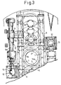
- Fig. 3 is a front view illustrating the relationship between the cutters and motors in Fig. 2.
- Fig. 4 is a side view of Fig. 3.
- Fig. 5 is a side view of when Fig. 3 is viewed from below.
- Fig. 6 is a side view illustrating the internal structure of Fig. 2.
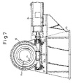
- Fig. 7 is a sectional view along the line A-A of Fig. 6.
- Fig. 8 is a diagram of operation illustrating the Locus of a cutter of when a round pipe is cut by the cutting machine for cutting round and square pipes of the present invention.
- Fig. 9 is a diagram of operation illustrating the locus of a cutter of when a square pipe is cut by the cutting machine for cutting round and square pipes of the present invention.
- Fig. 1 is a front view illustrating the whole cutting machine for cutting round and square pipes according to the present invention
- Fig. 2 is a side view thereof.
- a pair of sliders 4 is arranged on the surface 1a of a large disk 1 in the direction of its diameter to support cutters 2 at an equal distance from the center thereof and drive systems 3 therefor.
- the cutters 2 having a rotary disk type shape are for milling operations and have a milling blade and are rotated at a peripheral velocity of from about 200 to about 300 mm/min.
- reference numeral 5 denotes covers for the cutters 2.
- Figs. 3 to 5 illustrate the relationship between the cutters 2 and motors 6 for driving the cutters.
- To the disk 1 are fastened a pair of guide rails 7, 7 at the right and left at equal distances along a straight line connecting the centers of the cutters 2, 2, and the sliders 4 are guided by the guide rails to move on the surface 1a of the disk 1 in the direction of its diameter.
- the drive system 3 is drivably coupled to the motor 6 mounted on the back surface of the disk 1.
- a cutter shaft 2a of the cutter 2 is coupled to a motor shaft 6a via a gear train 3a in the drive system 3.
- a ball screw mechanism 8 fastened to one side of the disk 1 is provided with a movable ball case.
- a portion 9a of the case 9 extending toward the slider 4 is fastened to the slider 4. Therefore, the slider 4 moves on the guide rail 7 accompanying the motion of the ball case 9.
- reference numeral 10 denotes a spring for preventing the motion of the slider 4 with respect to the guide rail 7.
- the ball screw mechanism 8 operates via a pair of bevel gears 12 and 13 rotated by a servo motor 11 provided on the back surface of the disk 1 like the above-mentioned motor 6.
- the ball screw mechanism 8 comprises a threaded shaft 8a included in a known ball case 9, a ball nut, etc.
- the ball case 9 moves on the threaded shaft 8a to approach, or move away from, the center O of the disk 1.
- Fig. 6 which is a side view of the internal structure of Fig. 2, the disk 1 is fastened at its center to a horizontal hollow shaft 14 and is maintained upright, and the peripheral surface thereof is in contact with the outer peripheries of the right and left rollers 16, 16 that are provided on a machine frame 15 to rotate, in order to prevent deflection during the rotation.
- the horizontal hollow shaft 14 is supported at both its ends by bearings 17 and 18 provided in the machine frame 15 to rotate with respect to the machine frame 15.
- a worm wheel 19 is fastened to one end of the horizontal hollow shaft 14.
- a worm gear 20 provided on the side of the machine frame 14 is in mesh with the worm wheel 19 as shown in Fig.7, and a shaft 20a of the worm gear 20 is supported by bearings 21 and 22 on both sides to rotate.
- One end of the shaft 20a is coupled, via a joint 23, to a shaft 24a of a motor 24 for driving the disk 1 provided on the machine frame 15.
- the rotation of the motor 24 is transmitted to the worm wheel 19 from the worm gear 20, whereby the horizontal hollow shaft 14 rotates, and the disk 1 together therewith rotates in the direction of an arrow shown in Fig. 1.
- a pipe member worked into a plate by a rolling mill that is not shown is subjected to a next step to form an electro welded tube of a circular shape or a square shape and is fed from the right side in Fig. 6, and is inserted in a hole 14a of the horizontal hollow shaft 14 and is fed toward the left.
- reference numeral 25 denotes a front chuck for fastening the pipe inserted in the hole 14a of the horizontal hollow shaft 14, and 26 denotes a rear chuck, which both effect the fastening being actuated by air cylinders 27.
- guide rollers 30 and 31 On the front side of the guide roller 28 and on the rear side of the guide roller 29, furthermore, there are provided, neighboring thereto, guide rollers 30 and 31 for limiting the pipe in the right-and-left direction.
- both sides of the outer periphery of the pipe of a predetermined length are positioned by the guide rollers 28, 29, 30 and 31, and are clamped by the front chuck 25 and rear chuck 26 using the air cylinders 27 to be ready for the cutting operation.
- the front portion of the pipe is cut from the rear portion.
- the cutter 2A (cutter of the upper side) may be located at an angle ⁇ 1 from a horizontal line that passes through the center O of the disk 1.
- the servo motor 11 is then rotated so that the ball case 9 of the ball screw mechanism 8 approaches the center O of the disk 1 and that the center of the cutter 2A moves from a position A to a position B via the slider 4 and further moves inwards. Then, the blade tip of the cutter 2 comes into contact with the circumference of the round pipe P1 to start the cutting operation.
- the blade tip of the cutter 2A arrives at a position indicated by a two-dot chain line, and the outside wall t of the round pipe P1 is partly cut.
- the cutting is also effected by the cutter 2B (cutter 2 of the lower side) that is provided symmetrically with respect to the center O of the disk 1.
- the cutter 2A (the same also holds for 2B) on the disk 1 has a radius R1 of rotation
- the position C is shifted to a position D when the disk 1 is turned clockwise over an angle ⁇ 2 maintaining this radius R1.
- the pipe P1 that is fastened is cut the outside wall t on one side along the outer circumference thereof. Due to the cutter 2B, similarly, the outside wall t of the other side is cut along the outer circumference.
- ⁇ 2 is from 120° to 140°
- D denotes the diameter of a round pipe.
- a two-dot chain line in the round pipe P1 denotes the locus of the blade tip of the cutter 2.
- the disk 1 has a diameter of about 1600 mm.
- Fig. 9 illustrates the case where a pipe to be cut is a square pipe P2.
- the cutter 2A (cutter 2 of the upper side) is located at a position of an angle ⁇ 1 from a horizontal line that passes through the center O of the disk 1.
- the disk 1 is turned clockwise maintaining a radius R2 of rotation, and the servo motor 11 is rotated to bring the ball case 9 of the ball screw mechanism 8 close to the center O of the disk 1.
- the center of the cutter 2A moves from a position A to a position B via the slider 4 and further moves, whereby the blade tip of the cutter 2A comes into contact with the outer circumference of the square pipe P2 to start the cutting in the horizontal direction.
- the center of the cutter 2A moves from the position A, through the position B, up to a position C as shown to cut the outside wall t of the square pipe P2 along the horizontal direction.
- the cutter 2A is turned in the clockwise direction to cut a corner portion of the square pipe P2.
- the cutter 2A is then moved from a position E to a position F to finish the cutting of the outside wall t in the vertical direction.
- the cutter 2A returns from a position F to a position G, and is then turned in the counterclockwise direction by an angle ⁇ 2 to return to the initial Position A.
- ⁇ 2 120° to 140°.
- the outside wall t of the square pipe P2 is cut by the cutter 2B in the horizontal direction and in the vertical direction; i.e., the square pipe P2 is cut by the cutter 2.
- H denotes the width of the cross section of square pipe P2
- V denotes the height of the cross section
- RP denotes a radius of a circle in contact with the corners of the square pipe.
- the present invention makes it possible to cut the material without traversing it. Besides, since two pieces of cutters slide on the same plane of the disk, the sections by the blade tips of the pair of cutters are on the same plane and are favorably finished. Both round pipes and square pipes can be cut using the same cutting machine without the need of exchanging the cutters. Therefore, no work is required for the exchange operation, and the stroke of the cutters at the time of cutting can be decreased to equal only the outside wall. Besides, the structure of the cutting machine can be simplified.
Landscapes
- Engineering & Computer Science (AREA)
- Mechanical Engineering (AREA)
- Sawing (AREA)
- Nonmetal Cutting Devices (AREA)
Applications Claiming Priority (3)
| Application Number | Priority Date | Filing Date | Title |
|---|---|---|---|
| JP20336095A JPH0947914A (ja) | 1995-08-09 | 1995-08-09 | 丸・角パイプ切断機 |
| JP20336095 | 1995-08-09 | ||
| JP203360/95 | 1995-08-09 |
Publications (2)
| Publication Number | Publication Date |
|---|---|
| EP0757929A1 true EP0757929A1 (de) | 1997-02-12 |
| EP0757929B1 EP0757929B1 (de) | 1999-12-08 |
Family
ID=16472746
Family Applications (1)
| Application Number | Title | Priority Date | Filing Date |
|---|---|---|---|
| EP19960112803 Expired - Lifetime EP0757929B1 (de) | 1995-08-09 | 1996-08-08 | Schneidmaschine für Rund- oder Vierkantrohre |
Country Status (3)
| Country | Link |
|---|---|
| EP (1) | EP0757929B1 (de) |
| JP (1) | JPH0947914A (de) |
| DE (1) | DE69605492T2 (de) |
Cited By (4)
| Publication number | Priority date | Publication date | Assignee | Title |
|---|---|---|---|---|
| CN102528158A (zh) * | 2012-03-08 | 2012-07-04 | 浙江摩多巴克斯汽配有限公司 | 一种切割机 |
| WO2015119584A1 (en) * | 2014-02-06 | 2015-08-13 | Thaisakol Group Co., Ltd. | Shaft cutting machine that is able to cut short size shaft |
| CN107282982A (zh) * | 2017-07-27 | 2017-10-24 | 天津国际铁工焊接装备有限公司 | 一种圆管滚刀切割装置 |
| JP2023054660A (ja) * | 2021-10-04 | 2023-04-14 | 日鉄エンジニアリング株式会社 | 鋸断装置及び鋸断方法 |
Families Citing this family (4)
| Publication number | Priority date | Publication date | Assignee | Title |
|---|---|---|---|---|
| DE10354846B3 (de) * | 2003-11-24 | 2005-05-19 | Intega Hans J. Jehl Gmbh | Rohrschneidgerät |
| DE102009005983A1 (de) * | 2009-01-23 | 2010-07-29 | Illinois Tool Works Inc., Glenview | Rohrbearbeitungsvorrichtung |
| KR101407327B1 (ko) * | 2013-12-04 | 2014-06-13 | 디씨에스이엔지 주식회사 | 무선통신에 의해 절삭툴을 자유자재로 제어하여 원형 또는 각형 관재나 봉재를 원하는 형상으로 가공할 수 있는 장치 |
| ITUB20153283A1 (it) * | 2015-08-28 | 2017-02-28 | Mecolpress S P A | Apparecchiatura di taglio a caldo di billette |
Citations (8)
| Publication number | Priority date | Publication date | Assignee | Title |
|---|---|---|---|---|
| US2516817A (en) * | 1946-05-04 | 1950-07-25 | Acieries Ci Devant Georges Fis | Pipe cutter |
| GB884591A (en) * | 1959-02-18 | 1961-12-13 | Voucher Ltd | New or improved cold sawing machine |
| JPS5969212A (ja) | 1982-09-28 | 1984-04-19 | Sumitomo Heavy Ind Ltd | 公転式ミ−リングカツタ−を備えた鋼管切断機 |
| JPS5969213A (ja) | 1982-09-29 | 1984-04-19 | Sumitomo Heavy Ind Ltd | 公転式ミ−リングカツタを備えた鋼管切断機 |
| FR2564347A1 (fr) * | 1984-05-16 | 1985-11-22 | Vallourec | Procede de tronconnage de barres et dispositif pour sa mise en oeuvre |
| US4771667A (en) * | 1986-09-02 | 1988-09-20 | Metl-Saw System Inc | Precision metal cutting saw and assembly |
| DE4101749A1 (de) * | 1990-01-23 | 1991-07-25 | Mitsubishi Heavy Ind Ltd | Fahrbare stahlrohr-fraesschneidemaschine |
| DE4422935A1 (de) * | 1994-07-01 | 1996-01-04 | Heinz Juergen Marke | Sägevorrichtung |
-
1995
- 1995-08-09 JP JP20336095A patent/JPH0947914A/ja active Pending
-
1996
- 1996-08-08 EP EP19960112803 patent/EP0757929B1/de not_active Expired - Lifetime
- 1996-08-08 DE DE1996605492 patent/DE69605492T2/de not_active Expired - Lifetime
Patent Citations (9)
| Publication number | Priority date | Publication date | Assignee | Title |
|---|---|---|---|---|
| US2516817A (en) * | 1946-05-04 | 1950-07-25 | Acieries Ci Devant Georges Fis | Pipe cutter |
| GB884591A (en) * | 1959-02-18 | 1961-12-13 | Voucher Ltd | New or improved cold sawing machine |
| JPS5969212A (ja) | 1982-09-28 | 1984-04-19 | Sumitomo Heavy Ind Ltd | 公転式ミ−リングカツタ−を備えた鋼管切断機 |
| JPS5969213A (ja) | 1982-09-29 | 1984-04-19 | Sumitomo Heavy Ind Ltd | 公転式ミ−リングカツタを備えた鋼管切断機 |
| FR2564347A1 (fr) * | 1984-05-16 | 1985-11-22 | Vallourec | Procede de tronconnage de barres et dispositif pour sa mise en oeuvre |
| US4771667A (en) * | 1986-09-02 | 1988-09-20 | Metl-Saw System Inc | Precision metal cutting saw and assembly |
| DE4101749A1 (de) * | 1990-01-23 | 1991-07-25 | Mitsubishi Heavy Ind Ltd | Fahrbare stahlrohr-fraesschneidemaschine |
| JPH03221311A (ja) | 1990-01-23 | 1991-09-30 | Mitsubishi Heavy Ind Ltd | ミーリング式走行鋼管切断機 |
| DE4422935A1 (de) * | 1994-07-01 | 1996-01-04 | Heinz Juergen Marke | Sägevorrichtung |
Cited By (5)
| Publication number | Priority date | Publication date | Assignee | Title |
|---|---|---|---|---|
| CN102528158A (zh) * | 2012-03-08 | 2012-07-04 | 浙江摩多巴克斯汽配有限公司 | 一种切割机 |
| WO2015119584A1 (en) * | 2014-02-06 | 2015-08-13 | Thaisakol Group Co., Ltd. | Shaft cutting machine that is able to cut short size shaft |
| CN107282982A (zh) * | 2017-07-27 | 2017-10-24 | 天津国际铁工焊接装备有限公司 | 一种圆管滚刀切割装置 |
| CN107282982B (zh) * | 2017-07-27 | 2023-09-22 | 天津国际铁工焊接装备有限公司 | 一种圆管滚刀切割装置 |
| JP2023054660A (ja) * | 2021-10-04 | 2023-04-14 | 日鉄エンジニアリング株式会社 | 鋸断装置及び鋸断方法 |
Also Published As
| Publication number | Publication date |
|---|---|
| DE69605492T2 (de) | 2000-04-27 |
| JPH0947914A (ja) | 1997-02-18 |
| DE69605492D1 (de) | 2000-01-13 |
| EP0757929B1 (de) | 1999-12-08 |
Similar Documents
| Publication | Publication Date | Title |
|---|---|---|
| KR101718330B1 (ko) | 단부-절삭 공작물 휠의 톱니 에지를 기계가공하는 방법 및 장치 | |
| KR101995784B1 (ko) | 워크피스를 기계가공하기 위한 방법, 툴 장치 및 톱니 절삭 머신 | |
| US8424427B2 (en) | Method and apparatus for roll surface machining | |
| KR960006731B1 (ko) | 밀링식 주행강관 절단기 | |
| JP4381780B2 (ja) | スパイラルベベルギヤのcnc加工装置及びcnc加工装置によるスパイラルベベルギヤの加工方法 | |
| JP2005138207A (ja) | 開先の倣い加工装置 | |
| CN205324986U (zh) | 一种自动旋转跟随切管机 | |
| JPH0760542A (ja) | 内歯車状の工具によって歯車状のワークの歯面を仕上加工するための機械 | |
| KR101636758B1 (ko) | 회전속도비를 이용하여 회전체내 절삭툴을 제어할 수 있는 오비탈식 파이프 절삭장치 | |
| US5238337A (en) | Method of machining round material or the like by the whirling process | |
| JPH03178735A (ja) | 3―相―クランク軸加工 | |
| EP0757929B1 (de) | Schneidmaschine für Rund- oder Vierkantrohre | |
| US8529172B2 (en) | Edge milling device | |
| JPH058002Y2 (de) | ||
| US5063798A (en) | Running circular pipe cutting device | |
| US4288680A (en) | Apparatus for cutting mould notches for strip steel cutting tools | |
| US5787566A (en) | Method and apparatus for cutting flat stock | |
| US4116095A (en) | Metal sawing or milling machine | |
| KR100434182B1 (ko) | 엔드밀을 이용한 원통체의 내외면 홈 가공방법 및 장치 | |
| JP3422576B2 (ja) | 鋼管の切断方法 | |
| JPH07299625A (ja) | 棒材又は管材又は管材ブルームの切削加工方法及び装置 | |
| JP4486355B2 (ja) | リング材切断方法 | |
| US20040083866A1 (en) | Method and apparatus for saw cutting tubes | |
| JP2759919B2 (ja) | V溝加工機 | |
| US4626150A (en) | Machine tool for machining workpieces by chip removal according to a quadric surface of revolution, particularly for super finishing of cylindrical surfaces |
Legal Events
| Date | Code | Title | Description |
|---|---|---|---|
| PUAI | Public reference made under article 153(3) epc to a published international application that has entered the european phase |
Free format text: ORIGINAL CODE: 0009012 |
|
| AK | Designated contracting states |
Kind code of ref document: A1 Designated state(s): DE FR GB IT |
|
| 17P | Request for examination filed |
Effective date: 19970731 |
|
| GRAG | Despatch of communication of intention to grant |
Free format text: ORIGINAL CODE: EPIDOS AGRA |
|
| 17Q | First examination report despatched |
Effective date: 19990126 |
|
| GRAG | Despatch of communication of intention to grant |
Free format text: ORIGINAL CODE: EPIDOS AGRA |
|
| GRAG | Despatch of communication of intention to grant |
Free format text: ORIGINAL CODE: EPIDOS AGRA |
|
| GRAH | Despatch of communication of intention to grant a patent |
Free format text: ORIGINAL CODE: EPIDOS IGRA |
|
| GRAH | Despatch of communication of intention to grant a patent |
Free format text: ORIGINAL CODE: EPIDOS IGRA |
|
| GRAA | (expected) grant |
Free format text: ORIGINAL CODE: 0009210 |
|
| AK | Designated contracting states |
Kind code of ref document: B1 Designated state(s): DE FR GB IT |
|
| REF | Corresponds to: |
Ref document number: 69605492 Country of ref document: DE Date of ref document: 20000113 |
|
| ITF | It: translation for a ep patent filed | ||
| ET | Fr: translation filed | ||
| PLBE | No opposition filed within time limit |
Free format text: ORIGINAL CODE: 0009261 |
|
| STAA | Information on the status of an ep patent application or granted ep patent |
Free format text: STATUS: NO OPPOSITION FILED WITHIN TIME LIMIT |
|
| 26N | No opposition filed | ||
| REG | Reference to a national code |
Ref country code: GB Ref legal event code: IF02 |
|
| PGFP | Annual fee paid to national office [announced via postgrant information from national office to epo] |
Ref country code: GB Payment date: 20110803 Year of fee payment: 16 |
|
| GBPC | Gb: european patent ceased through non-payment of renewal fee |
Effective date: 20120808 |
|
| PG25 | Lapsed in a contracting state [announced via postgrant information from national office to epo] |
Ref country code: GB Free format text: LAPSE BECAUSE OF NON-PAYMENT OF DUE FEES Effective date: 20120808 |
|
| PGFP | Annual fee paid to national office [announced via postgrant information from national office to epo] |
Ref country code: DE Payment date: 20140806 Year of fee payment: 19 |
|
| PGFP | Annual fee paid to national office [announced via postgrant information from national office to epo] |
Ref country code: FR Payment date: 20140808 Year of fee payment: 19 |
|
| PGFP | Annual fee paid to national office [announced via postgrant information from national office to epo] |
Ref country code: IT Payment date: 20140821 Year of fee payment: 19 |
|
| REG | Reference to a national code |
Ref country code: DE Ref legal event code: R119 Ref document number: 69605492 Country of ref document: DE |
|
| PG25 | Lapsed in a contracting state [announced via postgrant information from national office to epo] |
Ref country code: IT Free format text: LAPSE BECAUSE OF NON-PAYMENT OF DUE FEES Effective date: 20150808 |
|
| REG | Reference to a national code |
Ref country code: FR Ref legal event code: ST Effective date: 20160429 |
|
| PG25 | Lapsed in a contracting state [announced via postgrant information from national office to epo] |
Ref country code: DE Free format text: LAPSE BECAUSE OF NON-PAYMENT OF DUE FEES Effective date: 20160301 |
|
| PG25 | Lapsed in a contracting state [announced via postgrant information from national office to epo] |
Ref country code: FR Free format text: LAPSE BECAUSE OF NON-PAYMENT OF DUE FEES Effective date: 20150831 |