EP0758074A2 - Arme jouet avec commande de la trajectoire du projectile - Google Patents
Arme jouet avec commande de la trajectoire du projectile Download PDFInfo
- Publication number
- EP0758074A2 EP0758074A2 EP96111702A EP96111702A EP0758074A2 EP 0758074 A2 EP0758074 A2 EP 0758074A2 EP 96111702 A EP96111702 A EP 96111702A EP 96111702 A EP96111702 A EP 96111702A EP 0758074 A2 EP0758074 A2 EP 0758074A2
- Authority
- EP
- European Patent Office
- Prior art keywords
- bullet
- spherical
- guiding portion
- sham
- barrel member
- Prior art date
- Legal status (The legal status is an assumption and is not a legal conclusion. Google has not performed a legal analysis and makes no representation as to the accuracy of the status listed.)
- Granted
Links
Images



Classifications
-
- F—MECHANICAL ENGINEERING; LIGHTING; HEATING; WEAPONS; BLASTING
- F41—WEAPONS
- F41B—WEAPONS FOR PROJECTING MISSILES WITHOUT USE OF EXPLOSIVE OR COMBUSTIBLE PROPELLANT CHARGE; WEAPONS NOT OTHERWISE PROVIDED FOR
- F41B11/00—Compressed-gas guns, e.g. air guns; Steam guns
- F41B11/80—Compressed-gas guns, e.g. air guns; Steam guns specially adapted for particular purposes
- F41B11/89—Compressed-gas guns, e.g. air guns; Steam guns specially adapted for particular purposes for toys
-
- F—MECHANICAL ENGINEERING; LIGHTING; HEATING; WEAPONS; BLASTING
- F41—WEAPONS
- F41B—WEAPONS FOR PROJECTING MISSILES WITHOUT USE OF EXPLOSIVE OR COMBUSTIBLE PROPELLANT CHARGE; WEAPONS NOT OTHERWISE PROVIDED FOR
- F41B11/00—Compressed-gas guns, e.g. air guns; Steam guns
-
- F—MECHANICAL ENGINEERING; LIGHTING; HEATING; WEAPONS; BLASTING
- F41—WEAPONS
- F41B—WEAPONS FOR PROJECTING MISSILES WITHOUT USE OF EXPLOSIVE OR COMBUSTIBLE PROPELLANT CHARGE; WEAPONS NOT OTHERWISE PROVIDED FOR
- F41B11/00—Compressed-gas guns, e.g. air guns; Steam guns
- F41B11/70—Details not provided for in F41B11/50 or F41B11/60
Definitions
- the present invention relates generally to a model gun with trajectory control function, and more particularly to an improvement in a model gun having trajectory control function in which a spherical sham bullet is temporarily put in a bullet holding portion provided just at the back of a barrel and then shot off through the barrel with gas pressure and the trajectory of the spherical sham bullet is controllable.
- model gun often called an air soft gun in which a bullet holding portion is provided just at the back of a barrel for holding temporarily a spherical sham bullet and the spherical sham bullet put temporarily in the bullet holding portion is shot off through the barrel with gas pressure supplied into the bullet holding portion.
- a model gun as often called the air soft gun
- the barrel is provided to be accompanied, at the back thereof, with a bullet shooting portion at which a spherical sham bullet is temporarily held, and a partitioned upper inner surface of a part of the barrel is formed with friction material so as to project slightly downward with the coefficient of friction thereof higher than that of a partitioned lower inner surface of the part of the barrel which is opposite to the partitioned upper inner surface.
- the amount of the downward projection of the partitioned upper inner surface is adjusted by a friction adjusting mechanism which works in response to the operation of a control handle, so that both of the partitioned upper and lower inner surfaces of the barrel come into contact with the spherical sham bullet which passes through the barrel after shooting from the bullet shooting portion.
- the spherical sham bullet with which both of the partitioned upper and lower inner surfaces of the barrel come into contact is given a rotation in such a rotating direction as to cause the spherical sham bullet to be subjected to dynamic lift with its forward movement due to a difference between the friction arising between the partitioned upper inner surface of the barrel and the spherical sham bullet and the friction arising between the partitioned lower inner surface of the barrel and the sham bullet. Consequently, the range of the spherical sham bullet shot off through the barrel can be extended without increasing its power.
- the rotation of the spherical sham bullet with which the spherical sham bullet is subjected to the dynamic lift with its forward movement is such a rotation as to move upward the front end of the spherical sham bullet moving forward in the right or left side view in the direction perpendicular to the forward movement of the spherical sham bullet.
- This rotation of the spherical sham bullet is referred to as an upward rotation, hereinafter.
- the upward rotation of the spherical sham bullet passing through the barrel is caused under a condition where the friction arising between the partitioned upper inner surface of the barrel and the spherical sham bullet passing through the barrel after shooting is arranged to be larger than the friction arising between the partitioned lower inner surface of the barrel and the spherical sham bullet passing through the barrel after shooting.
- the friction material which forms the partitioned upper inner surface of the barrel projecting slightly downward is operative to press the spherical sham bullet passing through the partitioned upper inner surface of the barrel downward to a partitioned lower inner surface of the barrel and therefore the spherical sham bullet having passed through the partitioned upper inner surface of the barrel moves forward to a muzzle provided on the barrel along a path deviated slightly downward from a longitudinal axis line in the barrel.
- the spherical sham bullet having passed through the partitioned upper inner surface of the barrel is put in a condition where a space is formed between an upper inner surface of the barrel and the spherical sham bullet and gas pressure with which the spherical sham bullet has been shot goes through the space forward to the muzzle.
- the gas pressure which goes through the space formed between the upper inner surface of the barrel and the spherical sham bullet from the rear to the front of the spherical sham bullet is undesirably operative to reduce the upward rotation of the spherical sham bullet which is given to the spherical sham bullet by the friction material which forms the partitioned upper inner surface of the barrel projecting slightly downward.
- the dynamic lift exerted on the spherical sham bullet with the upward rotation of the latter is so reduced as not to extend efficiently the range of the spherical sham bullet shot off through the barrel.
- the barrel is required to be subjected to a drilling process for forming thereon an opening through which the friction material is inserted into the barrel to form the partitioned upper inner surface of the barrel, and in addition, since the friction adjusting mechanism which comprises, for example, a cam member, a press member and so on for controlling the amount of projection of the friction material and the control handle accompanied with the friction adjusting mechanism are provided on the barrel which is provided with the opening through the drilling process, the whole construction containing the barrel comes undesirably to be complicated to use a large number of parts and to increase the cost of production.
- Another object of the present invention is to provide a model gun with trajectory control function, in which a spherical sham bullet is temporarily put in a bullet holding chamber provided just at the back of a barrel and then shot off through the barrel with gas pressure and the trajectory of the spherical sham bullet is able to be controlled for extending the range of the shame bullet, and with which a trajectory control for the spherical sham bullet is so performed as to extend efficiently the range of the shame bullet by means of a mechanism simplified in construction to use parts decreased in number and to reduce the cost of production.
- a further object of the present invention is to provide a model gun with trajectory control function, in which a spherical sham bullet is temporarily put in a bullet holding chamber provided just at the back of a barrel and then shot off through the barrel with gas pressure and the trajectory of the spherical sham bullet is able to be controlled for extending the range of the shame bullet, and with which the spherical sham bullet shot off through the barrel is effectively given an upward rotation in a trajectory control by means of a mechanism simplified in construction to use parts decreased in number and to reduce the cost of production, so that the range of the shame bullet is efficiently extended.
- a model gun with trajectory control function which comprises a barrel structure including an outer barrel member and an inner barrel member, a tubular member provided in a rear end portion of the outer barrel member for forming a bullet holding portion by which a spherical sham bullet is temporarily held to be shot with gas pressure and a bullet guiding portion by which the spherical sham bullet shot from the bullet holding portion is guided into the inner barrel member, and a slippery member having a bullet contacting surface lower in friction coefficient than an inner surface of the bullet guiding portion formed in the tubular member and provided on an inner surface of a lower part of the bullet guiding portion in such a manner that the bullet contacting surface is variable in position to move in a direction of diameter of the bullet guiding portion, wherein a trajectory of the spherical sham bullet shot off through the barrel structure is controlled in response to the position of the bullet contacting surface of the slippery member in the direction of diameter of the bullet guiding portion.
- the inner barrel member is provided with a tapered rear end portion having the thickness reduced gradually toward a rear edge of the inner barrel member, which is put between the inner surface of the lower part of the bullet guiding portion formed in the tubular member and a front end portion of the slippery member provided on the inner surface of the lower part of the bullet guiding portion, and the inner barrel member is provided to be movable forward and backward relatively to the outer barrel member.
- the front end portion of the slippery member is lifted from the inner surface of the lower part of the bullet guiding portion to rise or fall in accordance with the movement of the tapered rear end portion of the inner barrel member when the inner barrel member is moved forward and backward relatively to the outer barrel member, and thereby the position of the bullet contacting surface of the slippery member in the direction of diameter of the bullet guiding portion is controlled in response to the lift of the front end portion of the slippery member from the inner surface of the lower part of the bullet guiding portion.
- the spherical sham bullet with which both of the bullet contacting surface of the slippery member and the inner surface of the upper part of the bullet guiding portion come into contact is given an upward rotation due to a difference between the friction arising between the bullet contacting surface of the slippery member and the spherical sham bullet and the friction arising between the inner surface of the upper part of the bullet guiding portion and the spherical sham bullet.
- the bullet contacting surface of the slippery member is operative to press the spherical sham bullet passing through an interspace between the bullet contacting surface of the slippery member and the inner surface of the upper part of the bullet guiding portion upward to the inner surface of the upper part of the bullet guiding portion and therefore the spherical sham bullet guided through the bullet guiding portion into the inner barrel member moves forward in the inner barrel member to a muzzle provided on the barrel structure along a path deviated slightly upward from a longitudinal axis line in the inner barrel member.
- the spherical sham bullet moving forward in the inner barrel member is put in a condition where a space is formed between a lower inner surface of the inner barrel member and the spherical sham bullet and gas pressure with which the spherical sham bullet has been shot goes through the space forward to the muzzle.
- the gas pressure which goes through the space formed between the lower inner surface of the inner barrel member and the spherical sham bullet from the rear to the front of the spherical sham bullet is desirably operative to emphasize the upward rotation of the spherical sham bullet which is given to the spherical sham bullet when the spherical sham bullet passes through the interspace between the bullet contacting surface of the slippery member and the inner surface of the upper part of the bullet guiding portion.
- the dynamic lift exerted on the spherical sham bullet with the upward rotation of the latter is so amplified as to extend efficiently the range of the spherical sham bullet shot off through the barrel structure.
- the difference between the friction arising between the bullet contacting surface of the slippery member and the spherical sham bullet and the friction arising between the inner surface of the upper part of the bullet guiding portion and the spherical sham bullet is varied in response to the position of the bullet contacting surface of the slippery member in the direction of diameter of the bullet guiding portion, and therefore the upward rotation of the spherical sham bullet, which is given to the spherical sham bullet when the spherical sham bullet passes through the interspace between the bullet contacting surface of the slippery member and the inner surface of the upper part of the bullet guiding portion, is controlled in response to the position of the bullet contacting surface of the slippery member in the direction of diameter of the bullet guiding portion.
- the trajectory of the spherical sham bullet shot off through the barrel structure is controlled and adjusted in response to the position of the bullet contacting surface of the slippery member in the direction of diameter of the bullet guiding portion.
- a trajectory control in which the spherical sham bullet shot off through the barrel structure is effectively given the upward rotation by means of a mechanism which includes the outer and inner barrel members and the tubular member and the slippery member provided in the rear end potion of the outer barrel member and is relatively simplified in construction to use parts decreased in number and to reduce the cost of production so that the range of the spherical shame bullet is efficiently extended without increasing its power, is surely carried out.
- Fig. 1 shows an embodiment of model gun with trajectory control function according to the present invention.
- the embodiment has a barrel structure 1, a trigger 2, a hammer 3 rotating in cooperation with the trigger 2, a tubular member 4 positioned in a rear end portion of the barrel structure 1, a movable member 6 which is provided to be movable relatively to the tubular member 4 and in which a gas passage control valve 5 is provided, and a body 10 having a grip 7.
- the body 10 is further provided with a slider 11 which is movable forward and backward relatively to the barrel structure 1 and a case in which a pressure accumulating chamber which is charged with, for example, liquefied gas and a magazine for containing spherical sham bullets BB are provided is inserted to be detachable into the grip 7 (not shown in Fig. 1).
- one of the spherical sham bullets BB supplied from an upper end portion 13 of the magazine in the case inserted in the grip 7 is temporarily held and then shot to leave the tubular member 4 and the next spherical sham bullet BB is supplied from the upper end portion 13 of the magazine.
- the shooting of the spherical sham bullets BB held temporarily in the tubular member 4 and the supply of the spherical sham bullet BB into the tubular member 4 successive to the shooting are carried out with gas pressure discharged from the pressure accumulating chamber in the case inserted in the grip 7.
- the barrel structure 1 comprises an outer barrel member 8 and an inner barrel member 9 which is shorter in length than the outer barrel member 8 and inserted into the outer barrel member 8 to be movable forward and backward within a predetermined extent relatively to the outer barrel member 8.
- the tubular member 4 is provided in a rear end portion of the outer barrel member 8 which projects backward from a tapered rear end portion 9a of the inner barrel member 9.
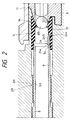
- the tubular member 4 is made in its entirety of elastic material, such as rubber or the like and forms a bullet holding portion 14 by which the spherical sham bullet BB supplied from the upper end portion 13 of the magazine in the case inserted into the grip 7 is temporarily held to be shot with the gas pressure and a bullet guiding portion 15 by which the spherical sham bullet BB shot from the bullet holding portion 14 is guided into the inner barrel member 9, as shown clearly in Fig. 2.
- the tapered rear end portion 9a of the inner barrel member 9 has the thickness thereof reduced gradually toward a rear edge of the inner barrel member 9 through which the spherical sham bullet BB is guided into the inner barrel member 9.
- the slider 11 which is provided to be movable forward and backward relatively to the barrel structure 1 is forced to be put in tendency of moving forward by a coil spring 16 provided in a portion of the body 10 under the barrel structure 1.
- a pressure chamber 17 having variable capacity is formed in a rear portion of the slider 11 and the movable member 6 is positioned between the tubular member 4 and the pressure chamber 17.
- the movable member 6 which has its mid portion making the upper end portion 13 of the magazine closed is moved back with the backward movement of the slider 11, so that the upper end portion 13 of the magazine is made open and one of the spherical sham bullets BB at the top in the magazine is pushed up into the upper end portion 13 of the magazine to be held therein by a coil spring provided in the magazine. Then, the movable member 6 is moved forward with the forward movement of the slider 11 so as to carry the spherical sham bullet BB in the upper end portion 13 of the magazine toward the tubular member 4 and the upper end portion 13 of the magazine is closed again.
- the spherical sham bullet BB carried into the tubular member 4 is temporarily held by the bullet holding portion 14 formed in the tubular member 4, as shown in Fig. 1.
- the gas passage control valve 5 in the movable member 6 is so positioned as to cause a front end thereof to come into contact with the spherical sham bullet BB held by the bullet holding portion 14 and thereby a gas passage through which a gas passage extending from the pressure accumulating chamber in the case inserted into the grip 7 is connected to the bullet holding portion 14 formed in the tubular member 4 is formed in the movable member 6.
- the hammer 3 is rotated to come down backward with the backward movement of the slider 11 and the hammer 3 having come down backward is maintained as it is after the slider 11 is moved forward to return to the reference position.
- the trigger 2 is pulled. Then, a driving mechanism which includes the hammer 3 rotating in cooperation with the trigger 2 is commenced to operate and thereby the hammer 3 is rotated to rise and a gas passage extending from the pressure accumulating chamber in the case inserted into the grip 7 is made open, so that a bullet shooting gas passage which extends from the pressure accumulating chamber in the case inserted into the grip 7 to the bullet holding portion 14 formed in the tubular member 4 is formed.
- the gas pressure discharged from the pressure accumulating chamber in the case inserted in the grip 7 is supplied through the bullet shooting gas passage into the bullet holding portion 14 formed in the tubular member 4 to act on the spherical sham bullet BB held temporarily by the bullet holding portion 14, so that the spherical sham bullet BB held in the bullet holding portion 14 is shot from the bullet holding portion 14 toward the bullet guiding portion 15 with the gas pressure. Then, the spherical sham bullet BB shot from the bullet holding portion 14 is guided through the bullet guiding portion 15 into the inner barrel member 9 to move forward in the inner barrel member 9 and shot off through the barrel structure 1.
- the gas passage control valve 5 which has been so positioned as to cause the front end thereof to come into contact with the spherical sham bullet BB held by the bullet holding portion 14 is moved forward with the gas pressure from the pressure accumulating chamber in the case inserted into the grip 7 to make the bullet shooting gas passage closed and to form a gas passage through which the gas passage extending from the pressure accumulating chamber in the case inserted into the grip 7 is connected to the pressure chamber 17, so that a blow-back gas passage which extends from the pressure accumulating chamber in the case inserted into the grip 7 to the pressure chamber 17 is formed.
- the gas pressure discharged from the pressure accumulating chamber in the case inserted into the grip 7 is supplied through the blow-back gas passage into the pressure chamber 17 to enlarge the capacity of the pressure chamber 17.
- a blow-back operation for moving the slider 11 back from the reference position and further for moving the movable member 6 back with the slider 11 is carried out.
- the gas pressure from the pressure accumulating chamber in the case inserted into the grip 7 is stopped to be supplied into the pressure chamber 17 and the gas pressure in the pressure chamber 17 is exhausted, so that the slider 11 having reached the rearmost position is moved forward by the coil spring 16 to return to the reference position together with the movable member 6.
- the next spherical sham bullet BB is supplied from the upper end portion 13 of the magazine to the tubular member 4 to be held by the bullet holding portion 14 formed in the tubular member 4.
- a slippery member 24 which is made of, for example, slippery synthetic resin material is provided on an inner surface of a lower part of the bullet guiding portion 15 formed in the tubular member 4.
- the slippery member 24 has a rear end portion 24b which is partially buried in the lower part of the bullet guiding portion 15, a front end portion 24a which is able to be lifted from the inner surface of the lower part of the bullet guiding portion 15, and a bullet contacting surface 24S which has a curvature along the inner surface of the lower part of the bullet guiding portion 15 and disposed to be opposite to an inner surface of an upper part of the bullet guiding portion 15, as shown in Fig. 5.
- the bullet contacting surface 24S of the slippery member 24 made of, for example, slippery synthetic resin material is lower in friction coefficient than the inner surface of the bullet guiding portion 15 formed in the tubular member 4.
- the front end portion 24a of the slippery member 24 is formed into a tapered portion having the thickness reduced gradually toward a front edge of the slippery member 24.
- the slippery member 24 is put in a condition where the rear end portion 24b is engaged with the lower part of the bullet guiding portion 15 and the front end portion 24a is rotatable within a predetermined angular extent with a pivot passing through the rear end portion 24b along a chord direction of the bullet guiding portion 15, so that the position of the bullet contacting surface 24S of the slippery member 24 is variable in the direction of diameter of the bullet guiding portion 15.
- threads of screw 9A are provided on an outer surface of the inner barrel member 9 and another threads of screw 8A are provided on an inner surface of the outer barrel member 8 for engaging with the threads of screw 9A provided on the outer surface of the inner barrel member 9.
- the tapered rear end portion 9a of the inner barrel member 9 is also moved forward and thereby the front end portion 24a of the slippery member 24 is rotated to a small extent with the pivot passing through the rear end portion 24b along the chord direction of the bullet guiding portion 15 to reduce the amount of the lift from the inner surface of the lower part of the bullet guiding portion 15, so that the position of the bullet contacting surface 24S of the slippery member 24 in the direction of diameter of the bullet guiding portion 15 becomes more distant from the inner surface of the upper part of the bullet guiding portion 15.
- the tapered rear end portion 9a of the inner barrel member 9 is also moved backward and thereby the front end portion 24a of the slippery member 24 is rotated to a small extent with the pivot passing through the rear end portion 24b along the chord direction of the bullet guiding portion 15 to increase the amount of the lift from the inner surface of the lower part of the bullet guiding portion 15, so that the position of the bullet contacting surface 24S of the slippery member 24 in the direction of diameter of the bullet guiding portion 15 becomes more close to the inner surface of the upper part of the bullet guiding portion 15.
- the position of the bullet contacting surface 24S of the slippery member 24 is varied in the direction of diameter of the bullet guiding portion 15 by rotating the inner barrel member 9 to be moved forward or backward relatively to the outer barrel member 8 with the threads of screw 9A engaged with the threads of screw 8A.
- the threads of screw 9A provided on the outer surface of the inner barrel member 9 and the threads of screw 8A provided on the inner surface of the outer barrel member 8 for engaging with the threads of screw 9A constitute a position adjusting mechanism 28 for adjusting the position of the bullet contacting surface 24S of the slippery member 24 in the direction of diameter of the bullet guiding portion 15.
- the inner barrel member 9 has a front edge 9b which faces to the outside of the barrel structure 1 through a muzzle 8a provided on a front end portion of the outer barrel member 8, as shown in Fig. 6.
- a pair of grooves 26 are provided on the front edge 9b of the inner barrel member 9 to be disposed along the direction of diameter of the inner barrel member 9. These grooves 26 are used for rotating the inner barrel member 9 relatively to the outer barrel member 8, for example, in such a manner that a blade portion of a screw driver is engaged with the grooves 26 to rotate the inner barrel member 9.
- the slippery member 24 having the bullet contacting surface 24S is provided on the inner surface of the lower part of the bullet guiding portion 15 formed in the tubular member 4 as described above, when the spherical sham bullet BB shot from the bullet holding portion 14 formed in the tubular member 4 with the gas pressure is guided through the bullet guiding portion 15 formed also in the tubular member 4 into the inner barrel member 9, both of the bullet contacting surface 24S of the slippery member 24 provided on the inner surface of the lower part of the bullet guiding portion 15 and the inner surface of the upper part of the bullet guiding portion 15, which is opposite to the bullet contacting surface 24S of the slippery member 24, come into contact with the spherical sham bullet BB which passes through an interspace between the bullet contacting surface 24S of the slippery member 24 and the inner surface of the upper part of the bullet guiding portion 15.
- the spherical sham bullet BB with which both of the bullet contacting surface 24S of the slippery member 24 and the inner surface of the upper part of the bullet guiding portion 15 come into contact is given an upward rotation, as shown with an arrow a in each of Figs.
- the upward rotation of the spherical sham bullet BB which is given to the spherical sham bullet BB when the spherical sham bullet BB passes through the interspace between the bullet contacting surface 24S of the slippery member 24 and the inner surface of the upper part of the bullet guiding portion 15, is varied in degree in response to the difference between the friction arising between the bullet contacting surface 24S of the slippery member 24 and the spherical sham bullet BB and the friction arising between the inner surface of the upper part of the bullet guiding portion 15 and the spherical sham bullet BB.
- the bullet contacting surface 24S of the slippery member 24 is operative to press the spherical sham bullet BB passing through the interspace between the bullet contacting surface 24S of the slippery member 24 and the inner surface of the upper part of the bullet guiding portion 15 upward to the inner surface of the upper part of the bullet guiding portion 15 and therefore the spherical sham bullet BB guided through the bullet guiding portion 15 into the inner barrel member 9 moves forward in the inner barrel member 9 to the muzzle 8a provided on the front end portion of the outer barrel member 8 along a path deviated slightly upward from a longitudinal axis line in the inner barrel member 9.
- the spherical sham bullet BB moving forward in the inner barrel member 9 is put in a condition where a space 27 is formed between a lower inner surface of the inner barrel member 9 and the spherical sham bullet BB, and the gas pressure with which the spherical sham bullet BB has been shot goes through the space 27 forward to the muzzle 8a, as shown with a plurality of allows in Fig. 8.
- the difference between the friction arising between the bullet contacting surface 24S of the slippery member 24 and the spherical sham bullet BB and the friction arising between the inner surface of the upper part of the bullet guiding portion 15 and the spherical sham bullet BB is varied in response to the position of the bullet contacting surface 24S of the slippery member 24 in the direction of diameter of the bullet guiding portion 15.
- the upward rotation of the spherical sham bullet BB which is given to the spherical sham bullet BB when the spherical sham bullet BB passes through the interspace between the bullet contacting surface 24S of the slippery member 24 and the inner surface of the upper part of the bullet guiding portion 15, is controlled in response to the position of the bullet contacting surface 24S of the slippery member 24 in the direction of diameter of the bullet guiding portion 15.
- a trajectory of the spherical sham bullet BB shot off through the barrel structure 1 is controlled and adjusted in response to the position of the bullet contacting surface 24S of the slippery member 24 in the direction of diameter of the bullet guiding portion 15.
- the adjustment of the position of the bullet contacting surface 24S of the slippery member 24 in the direction of diameter of the bullet guiding portion 15 by rotating the inner barrel member 9 to be moved forward or backward relatively to the outer barrel member 8 with the threads of screw 9A engaged with the threads of screw 8A is carried out also for the purpose of putting the spherical sham bullet BB guided through the bullet guiding portion 15 into the inner barrel member 9 in a condition where both of the bullet contacting surface 24S of the slippery member 24 and the inner surface of the upper part of the bullet guiding portion 15 come into contact appropriately with the spherical sham bullet BB.
- the position of the bullet contacting surface 24S of the slippery member 24 in the direction of diameter of the bullet guiding portion 15 is adjusted by rotating the inner barrel member 9 to be moved forward or backward relatively to the outer barrel member 8 with the threads of screw 9A engaged with the threads of screw 8A in order to absorb the undesirable variations in the inside diameter of the bullet guiding portion 15 formed in the tubular member 4 or in the outside diameter of the spherical sham bullet BB so as to obtain appropriate contacts between the spherical sham bullet BB and the bullet contacting surface 24S of the slippery member 24 and between the spherical sham bullet BB and the inner surface of the upper part of the bullet guiding portion 15, respectively.
- the bullet guiding portion 15 formed in the tubular member 4, the slippery member 24, the inner barrel member 9 provided with the threads of screw 9A, the outer barrel member 8 provided with the threads of screw 8A and so on constitute a trajectory control mechanism for controlling the trajectory of the spherical sham bullet BB shot off through the barrel structure 1.
- a trajectory control mechanism for controlling the trajectory of the spherical sham bullet BB shot off through the barrel structure 1.
Landscapes
- Engineering & Computer Science (AREA)
- General Engineering & Computer Science (AREA)
- Toys (AREA)
- Control Of Electric Motors In General (AREA)
- Electrophonic Musical Instruments (AREA)
- Stored Programmes (AREA)
- Control Of Position, Course, Altitude, Or Attitude Of Moving Bodies (AREA)
- Feedback Control In General (AREA)
- Measurement And Recording Of Electrical Phenomena And Electrical Characteristics Of The Living Body (AREA)
- Aiming, Guidance, Guns With A Light Source, Armor, Camouflage, And Targets (AREA)
- Control Of Positive-Displacement Air Blowers (AREA)
Applications Claiming Priority (3)
| Application Number | Priority Date | Filing Date | Title |
|---|---|---|---|
| JP19825795A JP2710918B2 (ja) | 1995-08-03 | 1995-08-03 | 弾道調整機能を有した玩具銃 |
| JP198257/95 | 1995-08-03 | ||
| JP19825795 | 1995-08-03 |
Publications (3)
| Publication Number | Publication Date |
|---|---|
| EP0758074A2 true EP0758074A2 (fr) | 1997-02-12 |
| EP0758074A3 EP0758074A3 (fr) | 1998-01-07 |
| EP0758074B1 EP0758074B1 (fr) | 2001-01-24 |
Family
ID=16388126
Family Applications (1)
| Application Number | Title | Priority Date | Filing Date |
|---|---|---|---|
| EP19960111702 Expired - Lifetime EP0758074B1 (fr) | 1995-08-03 | 1996-07-19 | Arme jouet avec commande de la trajectoire du projectile |
Country Status (11)
| Country | Link |
|---|---|
| US (1) | US5655510A (fr) |
| EP (1) | EP0758074B1 (fr) |
| JP (1) | JP2710918B2 (fr) |
| KR (1) | KR100191698B1 (fr) |
| AT (1) | ATE198932T1 (fr) |
| AU (1) | AU679884B2 (fr) |
| CA (1) | CA2182149C (fr) |
| DE (1) | DE69611641T2 (fr) |
| DK (1) | DK0758074T3 (fr) |
| ES (1) | ES2153521T3 (fr) |
| TW (1) | TW299663U (fr) |
Cited By (3)
| Publication number | Priority date | Publication date | Assignee | Title |
|---|---|---|---|---|
| WO1999020970A1 (fr) * | 1997-10-16 | 1999-04-29 | Galactic Systemz, Inc. | Pistolet pour projectiles a peinture de type 'paint-ball' |
| AU717907B2 (en) * | 1997-10-16 | 2000-04-06 | Western Arms Corporation | Model gun with automatic bullet supplying mechanism |
| EP1416244A1 (fr) * | 2002-10-30 | 2004-05-06 | Western Arms | Arme-jouet |
Families Citing this family (24)
| Publication number | Priority date | Publication date | Assignee | Title |
|---|---|---|---|---|
| JP3454070B2 (ja) * | 1997-03-04 | 2003-10-06 | ミノルタ株式会社 | 負荷電性トナー |
| US6213112B1 (en) * | 1998-08-17 | 2001-04-10 | Ari M. Squire | Bolt for a paint ball gun |
| US6324779B1 (en) | 1999-06-14 | 2001-12-04 | Tippmann Pneumatics, Inc. | Gun having a curved barrel |
| US6805111B2 (en) * | 1999-06-14 | 2004-10-19 | Tippmann Pneumatics, Llc | Gun |
| US6494194B2 (en) * | 2000-03-09 | 2002-12-17 | Zakrytoe aktsionernoe obschhestvo “Group Anics” | Multi-charge gas-cylinder pistol |
| US6820608B2 (en) * | 2001-01-09 | 2004-11-23 | New-Matics Licencing, Llc | Compressed gas-powered gun simulating the recoil of a conventional firearm |
| JP3708936B2 (ja) * | 2003-07-29 | 2005-10-19 | 株式会社ウエスタン・アームス | ガス圧を利用する玩具銃 |
| FR2860064B1 (fr) * | 2003-09-18 | 2007-11-02 | Cybergun Sa | Dispositif de correction de la trajectoire des projectiles dans une replique d'arme |
| US7762248B1 (en) | 2006-11-07 | 2010-07-27 | Rob Squire | Magnetic paint ball gun bolt apparatus |
| US8037877B2 (en) * | 2008-12-24 | 2011-10-18 | Yao-Gwo Gan | Barrel for prohibiting paintball from dropping therefrom |
| US20100229844A1 (en) * | 2009-03-16 | 2010-09-16 | Thomas Gore | Breech seal for air gun |
| CN102478372A (zh) * | 2010-11-30 | 2012-05-30 | 廖彦婷 | 一种玩具枪及其液态高压气体储气室安全气化系统 |
| TW201243268A (en) * | 2011-04-28 | 2012-11-01 | Yih Kai Entpr Co Ltd | Ballistic adjustment device of toy gun |
| US8833352B2 (en) * | 2011-06-24 | 2014-09-16 | Real Action Paintball (Rap4), Inc. | Method and apparatus for controlling paintball loading using a detent |
| US9103624B1 (en) * | 2014-05-15 | 2015-08-11 | Vega Force International Corp. | Ballistic trajectory adjustment mechanism for toy gun |
| TWM496755U (zh) * | 2014-10-24 | 2015-03-01 | zhuo-wei Zou | 玩具槍進彈定位裝置 |
| KR101878568B1 (ko) * | 2016-11-16 | 2018-07-13 | 윤상수 | 완구총 탄환 감속기 |
| TWM556841U (zh) * | 2017-07-07 | 2018-03-11 | Guay Guay Trading Co Ltd | 槍體彈道調整結構 |
| TWM565296U (zh) * | 2018-05-24 | 2018-08-11 | 巍嘉國際股份有限公司 | Ballistic adjustment structure of toy gun |
| US10890405B1 (en) * | 2019-07-01 | 2021-01-12 | Sang su Yoon | Non-tilting outer barrel for toy gun |
| TWM585342U (zh) * | 2019-07-25 | 2019-10-21 | 奕凱企業股份有限公司 | 玩具槍的彈道調整裝置 |
| JP7693194B2 (ja) * | 2021-02-26 | 2025-06-17 | 株式会社東京マルイ | 玩具銃、ホップ生成部およびホップアップ調整部 |
| KR102726379B1 (ko) * | 2021-04-08 | 2024-11-05 | 해인씨앤아이주식회사 | 비건 쌀빵의 제조방법 |
| TWM653374U (zh) * | 2023-08-04 | 2024-04-01 | 怪怪貿易股份有限公司 | 玩具槍之調整裝置 |
Family Cites Families (10)
| Publication number | Priority date | Publication date | Assignee | Title |
|---|---|---|---|---|
| US1379403A (en) * | 1920-07-13 | 1921-05-24 | Charles R Green | Pneumatic ball-projector |
| US2182369A (en) * | 1939-01-23 | 1939-12-05 | Christopher T Barron | Baseball projecting apparatus |
| US3838676A (en) * | 1972-09-28 | 1974-10-01 | E Kahelin | Ball throwing machine with barrel extension |
| US4091791A (en) * | 1975-09-19 | 1978-05-30 | Instrument Services, Inc. | Ball throwing machine |
| DD243334A1 (de) * | 1985-12-13 | 1987-02-25 | Fahrzeug U Jagdwaffen Werk Ern | Geschosslager fuer druckluftschusswaffen |
| US5265583A (en) * | 1991-06-05 | 1993-11-30 | Otto Carlos F | Automatic ball control apparatus |
| JP3020739B2 (ja) * | 1992-06-13 | 2000-03-15 | 株式会社シェリフ | エアーガンの発射方法とその装置 |
| JPH0721398B2 (ja) * | 1992-06-22 | 1995-03-08 | 株式会社東京マルイ | 玩具銃における弾丸のホップアップ装置 |
| JPH0721398A (ja) * | 1994-05-20 | 1995-01-24 | Casio Comput Co Ltd | 図形描画装置 |
| US5413085A (en) * | 1994-07-07 | 1995-05-09 | Kraeft; Robert W. | Apparatus and method for directing and controlling propelled balls |
-
1995
- 1995-08-03 JP JP19825795A patent/JP2710918B2/ja not_active Expired - Fee Related
-
1996
- 1996-02-09 TW TW085202292U patent/TW299663U/zh unknown
- 1996-07-16 AU AU60518/96A patent/AU679884B2/en not_active Ceased
- 1996-07-16 US US08/680,950 patent/US5655510A/en not_active Expired - Fee Related
- 1996-07-19 DK DK96111702T patent/DK0758074T3/da active
- 1996-07-19 ES ES96111702T patent/ES2153521T3/es not_active Expired - Lifetime
- 1996-07-19 AT AT96111702T patent/ATE198932T1/de not_active IP Right Cessation
- 1996-07-19 DE DE69611641T patent/DE69611641T2/de not_active Expired - Fee Related
- 1996-07-19 EP EP19960111702 patent/EP0758074B1/fr not_active Expired - Lifetime
- 1996-07-26 CA CA002182149A patent/CA2182149C/fr not_active Expired - Fee Related
- 1996-08-02 KR KR1019960032295A patent/KR100191698B1/ko not_active Expired - Fee Related
Cited By (3)
| Publication number | Priority date | Publication date | Assignee | Title |
|---|---|---|---|---|
| WO1999020970A1 (fr) * | 1997-10-16 | 1999-04-29 | Galactic Systemz, Inc. | Pistolet pour projectiles a peinture de type 'paint-ball' |
| AU717907B2 (en) * | 1997-10-16 | 2000-04-06 | Western Arms Corporation | Model gun with automatic bullet supplying mechanism |
| EP1416244A1 (fr) * | 2002-10-30 | 2004-05-06 | Western Arms | Arme-jouet |
Also Published As
| Publication number | Publication date |
|---|---|
| CA2182149A1 (fr) | 1997-02-04 |
| KR100191698B1 (ko) | 1999-06-15 |
| KR970011773A (ko) | 1997-03-27 |
| DK0758074T3 (da) | 2001-02-05 |
| EP0758074B1 (fr) | 2001-01-24 |
| ES2153521T3 (es) | 2001-03-01 |
| DE69611641T2 (de) | 2001-06-13 |
| JP2710918B2 (ja) | 1998-02-10 |
| TW299663U (en) | 1997-03-01 |
| AU679884B2 (en) | 1997-07-10 |
| US5655510A (en) | 1997-08-12 |
| DE69611641D1 (de) | 2001-03-01 |
| HK1005149A1 (en) | 1998-12-24 |
| CA2182149C (fr) | 1999-07-13 |
| ATE198932T1 (de) | 2001-02-15 |
| JPH0942892A (ja) | 1997-02-14 |
| AU6051896A (en) | 1997-02-20 |
| EP0758074A3 (fr) | 1998-01-07 |
Similar Documents
| Publication | Publication Date | Title |
|---|---|---|
| EP0758074B1 (fr) | Arme jouet avec commande de la trajectoire du projectile | |
| EP0647825B1 (fr) | Arme jouet avec un système d'alimentation automatique des projectiles | |
| JP2989162B2 (ja) | 自動弾丸供給機構付玩具銃 | |
| US7387117B2 (en) | Gas powered toy gun | |
| EP0625689B1 (fr) | Arme à air comprimé de tir semi-automatique | |
| US4358041A (en) | Powder-actuated tool with power adjustment and angle-fire control | |
| KR20050001309A (ko) | 가스식 완구총의 가스 공급 기구 | |
| HK1005149B (en) | Model gun with trajectory control function | |
| JP2960023B2 (ja) | 自動連射型玩具銃 | |
| US4333595A (en) | Offset piston for powder actuated tools | |
| EP0524129A1 (fr) | Dispositif pour le chargement de munitions pour arme à air comprimé | |
| JP2871582B2 (ja) | 玩具ガス銃 | |
| JP3041544B2 (ja) | 玩具銃における弾丸の発射装置 | |
| JP2587906B2 (ja) | 玩具銃 | |
| US3497984A (en) | Air operated projectile firing apparatus | |
| JP2871583B2 (ja) | ガス圧力式玩具銃 | |
| JPH0717982Y2 (ja) | ガス銃における弾丸装填部材 | |
| JPH0547991Y2 (fr) | ||
| JP3502780B2 (ja) | 自動弾丸供給機構付玩具銃 | |
| JPH0547992Y2 (fr) | ||
| JPS63231200A (ja) | 玩具銃における弾丸の発射方法 | |
| JP2003194496A (ja) | 玩具エアーガン | |
| HK1010752B (en) | Semi-automatic air gun | |
| HK1070937B (en) | Gas powered toy gun | |
| PL128739B2 (en) | Pneumatic gun chamber for pneumatic guns of piston-reservoir type |
Legal Events
| Date | Code | Title | Description |
|---|---|---|---|
| PUAI | Public reference made under article 153(3) epc to a published international application that has entered the european phase |
Free format text: ORIGINAL CODE: 0009012 |
|
| AK | Designated contracting states |
Kind code of ref document: A2 Designated state(s): AT BE CH DE DK ES FR GB IT LI NL SE |
|
| PUAL | Search report despatched |
Free format text: ORIGINAL CODE: 0009013 |
|
| AK | Designated contracting states |
Kind code of ref document: A3 Designated state(s): AT BE CH DE DK ES FR GB IT LI NL SE |
|
| 17P | Request for examination filed |
Effective date: 19980310 |
|
| 17Q | First examination report despatched |
Effective date: 19990622 |
|
| GRAG | Despatch of communication of intention to grant |
Free format text: ORIGINAL CODE: EPIDOS AGRA |
|
| GRAG | Despatch of communication of intention to grant |
Free format text: ORIGINAL CODE: EPIDOS AGRA |
|
| GRAH | Despatch of communication of intention to grant a patent |
Free format text: ORIGINAL CODE: EPIDOS IGRA |
|
| GRAH | Despatch of communication of intention to grant a patent |
Free format text: ORIGINAL CODE: EPIDOS IGRA |
|
| GRAA | (expected) grant |
Free format text: ORIGINAL CODE: 0009210 |
|
| AK | Designated contracting states |
Kind code of ref document: B1 Designated state(s): AT BE CH DE DK ES FR GB IT LI NL SE |
|
| REF | Corresponds to: |
Ref document number: 198932 Country of ref document: AT Date of ref document: 20010215 Kind code of ref document: T |
|
| ITF | It: translation for a ep patent filed | ||
| REG | Reference to a national code |
Ref country code: CH Ref legal event code: NV Representative=s name: A. BRAUN, BRAUN, HERITIER, ESCHMANN AG PATENTANWAE Ref country code: CH Ref legal event code: EP |
|
| REG | Reference to a national code |
Ref country code: DK Ref legal event code: T3 |
|
| REF | Corresponds to: |
Ref document number: 69611641 Country of ref document: DE Date of ref document: 20010301 |
|
| REG | Reference to a national code |
Ref country code: ES Ref legal event code: FG2A Ref document number: 2153521 Country of ref document: ES Kind code of ref document: T3 |
|
| ET | Fr: translation filed | ||
| PLBE | No opposition filed within time limit |
Free format text: ORIGINAL CODE: 0009261 |
|
| STAA | Information on the status of an ep patent application or granted ep patent |
Free format text: STATUS: NO OPPOSITION FILED WITHIN TIME LIMIT |
|
| REG | Reference to a national code |
Ref country code: GB Ref legal event code: IF02 |
|
| 26N | No opposition filed | ||
| PGFP | Annual fee paid to national office [announced via postgrant information from national office to epo] |
Ref country code: AT Payment date: 20050628 Year of fee payment: 10 |
|
| PGFP | Annual fee paid to national office [announced via postgrant information from national office to epo] |
Ref country code: NL Payment date: 20050718 Year of fee payment: 10 |
|
| PGFP | Annual fee paid to national office [announced via postgrant information from national office to epo] |
Ref country code: ES Payment date: 20050721 Year of fee payment: 10 |
|
| PGFP | Annual fee paid to national office [announced via postgrant information from national office to epo] |
Ref country code: SE Payment date: 20050722 Year of fee payment: 10 Ref country code: DK Payment date: 20050722 Year of fee payment: 10 Ref country code: CH Payment date: 20050722 Year of fee payment: 10 |
|
| PGFP | Annual fee paid to national office [announced via postgrant information from national office to epo] |
Ref country code: BE Payment date: 20050725 Year of fee payment: 10 |
|
| PG25 | Lapsed in a contracting state [announced via postgrant information from national office to epo] |
Ref country code: AT Free format text: LAPSE BECAUSE OF NON-PAYMENT OF DUE FEES Effective date: 20060719 |
|
| PG25 | Lapsed in a contracting state [announced via postgrant information from national office to epo] |
Ref country code: SE Free format text: LAPSE BECAUSE OF NON-PAYMENT OF DUE FEES Effective date: 20060720 |
|
| PG25 | Lapsed in a contracting state [announced via postgrant information from national office to epo] |
Ref country code: LI Free format text: LAPSE BECAUSE OF NON-PAYMENT OF DUE FEES Effective date: 20060731 Ref country code: DK Free format text: LAPSE BECAUSE OF NON-PAYMENT OF DUE FEES Effective date: 20060731 Ref country code: CH Free format text: LAPSE BECAUSE OF NON-PAYMENT OF DUE FEES Effective date: 20060731 Ref country code: BE Free format text: LAPSE BECAUSE OF NON-PAYMENT OF DUE FEES Effective date: 20060731 |
|
| PGFP | Annual fee paid to national office [announced via postgrant information from national office to epo] |
Ref country code: IT Payment date: 20060731 Year of fee payment: 11 |
|
| PG25 | Lapsed in a contracting state [announced via postgrant information from national office to epo] |
Ref country code: NL Free format text: LAPSE BECAUSE OF NON-PAYMENT OF DUE FEES Effective date: 20070201 |
|
| REG | Reference to a national code |
Ref country code: DK Ref legal event code: EBP |
|
| REG | Reference to a national code |
Ref country code: CH Ref legal event code: PL |
|
| EUG | Se: european patent has lapsed | ||
| NLV4 | Nl: lapsed or anulled due to non-payment of the annual fee |
Effective date: 20070201 |
|
| REG | Reference to a national code |
Ref country code: ES Ref legal event code: FD2A Effective date: 20060720 |
|
| BERE | Be: lapsed |
Owner name: *WESTERN ARMS Effective date: 20060731 |
|
| PGFP | Annual fee paid to national office [announced via postgrant information from national office to epo] |
Ref country code: GB Payment date: 20070730 Year of fee payment: 12 |
|
| PG25 | Lapsed in a contracting state [announced via postgrant information from national office to epo] |
Ref country code: ES Free format text: LAPSE BECAUSE OF NON-PAYMENT OF DUE FEES Effective date: 20060720 |
|
| PGFP | Annual fee paid to national office [announced via postgrant information from national office to epo] |
Ref country code: DE Payment date: 20070928 Year of fee payment: 12 |
|
| PGFP | Annual fee paid to national office [announced via postgrant information from national office to epo] |
Ref country code: FR Payment date: 20070718 Year of fee payment: 12 |
|
| GBPC | Gb: european patent ceased through non-payment of renewal fee |
Effective date: 20080719 |
|
| PG25 | Lapsed in a contracting state [announced via postgrant information from national office to epo] |
Ref country code: DE Free format text: LAPSE BECAUSE OF NON-PAYMENT OF DUE FEES Effective date: 20090203 |
|
| REG | Reference to a national code |
Ref country code: FR Ref legal event code: ST Effective date: 20090331 |
|
| PG25 | Lapsed in a contracting state [announced via postgrant information from national office to epo] |
Ref country code: GB Free format text: LAPSE BECAUSE OF NON-PAYMENT OF DUE FEES Effective date: 20080719 |
|
| PG25 | Lapsed in a contracting state [announced via postgrant information from national office to epo] |
Ref country code: FR Free format text: LAPSE BECAUSE OF NON-PAYMENT OF DUE FEES Effective date: 20080731 |
|
| PG25 | Lapsed in a contracting state [announced via postgrant information from national office to epo] |
Ref country code: IT Free format text: LAPSE BECAUSE OF NON-PAYMENT OF DUE FEES Effective date: 20070719 |