EP0758169A2 - Übertragungssystem und Übertragungsverfahren mit Wellenlängenmultiplexen - Google Patents
Übertragungssystem und Übertragungsverfahren mit Wellenlängenmultiplexen Download PDFInfo
- Publication number
- EP0758169A2 EP0758169A2 EP96112829A EP96112829A EP0758169A2 EP 0758169 A2 EP0758169 A2 EP 0758169A2 EP 96112829 A EP96112829 A EP 96112829A EP 96112829 A EP96112829 A EP 96112829A EP 0758169 A2 EP0758169 A2 EP 0758169A2
- Authority
- EP
- European Patent Office
- Prior art keywords
- channel
- signal
- signal light
- wavelength
- optical transmission
- Prior art date
- Legal status (The legal status is an assumption and is not a legal conclusion. Google has not performed a legal analysis and makes no representation as to the accuracy of the status listed.)
- Withdrawn
Links
- 230000005540 biological transmission Effects 0.000 title claims abstract description 85
- 230000003287 optical effect Effects 0.000 title claims description 58
- 238000000034 method Methods 0.000 title claims 9
- 238000001514 detection method Methods 0.000 claims abstract description 11
- 230000000875 corresponding effect Effects 0.000 description 14
- 238000010586 diagram Methods 0.000 description 6
- 238000010276 construction Methods 0.000 description 3
- 230000001276 controlling effect Effects 0.000 description 2
- 239000013307 optical fiber Substances 0.000 description 2
- 230000002730 additional effect Effects 0.000 description 1
- 230000002411 adverse Effects 0.000 description 1
- 230000002596 correlated effect Effects 0.000 description 1
- 230000002401 inhibitory effect Effects 0.000 description 1
- 230000008054 signal transmission Effects 0.000 description 1
Images


Classifications
-
- H—ELECTRICITY
- H04—ELECTRIC COMMUNICATION TECHNIQUE
- H04J—MULTIPLEX COMMUNICATION
- H04J14/00—Optical multiplex systems
- H04J14/02—Wavelength-division multiplex systems
-
- H—ELECTRICITY
- H04—ELECTRIC COMMUNICATION TECHNIQUE
- H04J—MULTIPLEX COMMUNICATION
- H04J14/00—Optical multiplex systems
- H04J14/02—Wavelength-division multiplex systems
- H04J14/0298—Wavelength-division multiplex systems with sub-carrier multiplexing [SCM]
Definitions
- the present invention relates to a wavelength division multiplexing optical transmission system and, more particularly, to an art for selecting a signal light of any desired channel therein.
- wavelength division multiplexing (WDM) optical transmission system In an optical communication field, a wavelength division multiplexing (WDM) optical transmission system has been studied for systematizing a large capacity communication system allowing for a large transmission capacity.
- This transmission system through wavelength division multiplexing is provided with a plurality of signal light sources, each of the signal light sources has a different wavelength in order to increase the signal transmission capacity.
- the signal speed of each channel is independently set, which has been highly expected to be put into an industrial use in near future.
- Fig. 3 is a block diagram of a construction of a conventional wavelength division multiplexing optical transmission system as described above.
- signal light sources 2-1 to 2-n are provided with the respective channels for generating signal lights having different wavelength ⁇ 1 to ⁇ n corresponding to the respective channels.
- a reference numeral 8 is a modulator for data modulating the signal light sources 2-1 to 2-n.
- a reference numeral 3 is a multiplexer comprising a coupler or the like for wavelength multiplexing each signal light having different wavelength ⁇ 1 to ⁇ n, which is transmitted to an optical transmission path 4 consisting of an optical fiber.
- a reference numeral 5 is a wavelength division unit for dividing the wavelength of the wavelength multiplexing light via the optical transmission path 4.
- Reference numerals 6-1 to 6-n are filters for receiving each wavelength multiplexing light which has been wavelength divided in the wavelength division unit 5. In accordance with the wavelength ranging from ⁇ 1 to ⁇ n of the respective filters 6-1 to 6-n, the signal light of a predetermined wavelength is selectively permeated.
- Reference numerals 7-1 to 7-n are optical detectors for receiving outputs of the corresponding filters 6-1 to 6-n, respectively.
- the optical detectors 7-1 to 7-n detect the signal light of the predetermined channel (wavelength).
- each of filters 6-1 to 6-n at a reception section is preliminarily set and fixed to have a wavelength selection characteristic so as to select a signal light of a predetermined channel.
- light sources 2-1 to 2-n at a transmission section and optical detectors 7-1 to 7-n at a reception section are fixedly correlated and defined by the wavelength selection characteristics of filters 6-1 to 6-n. Once each correlation between the light source and the optical detector is defined, any further selection of the desired correlation is not allowed.
- a wavelength division multiplexing optical transmission system comprising: a transmission section having: signal light generation means for generating a plurality of signal lights, each of said signal lights has a different wavelength in accordance with each channel; and multiplexing means for multiplexing said signal lights into a transmission signal light and transmitting said transmission signal light to an optical transmission path, and a reception section having: wavelength division means for wavelength dividing said transmission signal light that has been received; filter means for selecting a signal light of a predetermined channel among transmission signal lights from said wavelength division means in accordance with a wavelength selection characteristic controlled based on a control signal; and control means for generating said control signal that controls said wavelength selection characteristic so that a signal light of said predetermined channel is selected.
- the present invention is characterized in that the wavelength selection characteristic of the filter can be variably controlled in accordance with the selected channel.
- the signal light of each channel is modulated with channel information, i.e., the frequency corresponding to the channel through a predetermined modulation mode. As a result, each signal light is superimposed with the channel information.
- the modulation frequency as the channel information is detected. Based on the detected frequency, the wavelength selection characteristic of the wavelength variable filter is controlled. This allows for selectively receiving the signal light of the desired channel.
- the wavelength selection characteristics of the wavelength variable filter at the reception section can be externally controlled based on the channel information. As a result, the signal light of the desired channel can be selectively received.
- a first embodiment is hereinafter described.
- Fig. 1 is a block diagram of an embodiment of the present invention. The parts equivalent to those shown in Fig. 3 are designated as the same reference numerals as those in Fig. 3.
- reference numerals 1-1 to 1-n are oscillators, each of the oscillators is provided with the corresponded channel, respectively.
- the oscillators 1-1 to 1-n ocsillate signals at frequencies f1 to fn corresponding to the respective channels.
- Each frequency of f1 to fn is referenced as channel information for identifying each channel.
- Reference numerals 2-1 to 2-n are laser light sources, each of the laser light sources is provided with the corresponding channel. Each of the laser light sources 2-1 to 2-n generates the signal light having different wavelength ⁇ 1 to ⁇ n at every channel.
- Reference numerals 11-1 to 11-n are first modulators, each of the modulators is provided with the corresponding channel.
- the modulators 11-1 to 11-n amplitude modulate signal lights of the laser light sources 2-1 to 2-n at the respective frequencies f1 to fn.
- Reference numerals 12-1 to 12-n are second modulators, each of the second modulators is provided with the corresponding channel.
- the second modulators 12-1 to 12-n modulate signal lights of the first modulators 11-1 to 11-n with data signals, respectively.
- the signal light is wavelength multiplexed in the multiplexer 3, from which the signal light corresponding to n channel is transmitted to one optical transmission path 4.
- a reference numeral 5 is a wavelength division unit for wavelength dividing the signal light received from the optical transmission path 4, which is supplied to each of the wavelength variable filters 13-1 to 13-n, respectively.
- Reference numerals 13-1 to 13-n are wavelength variable filters in which wavelength selection characteristics can be varied through control of the respective controllers 15-1 to 15-n (described later).
- Reference numerals 14-1 to 14-n are optical detectors for receiving an input of each signal light which has been selectively permeated through the variable filters 13-1 to 13-n, respectively.
- Each of the optical detectors 14-1 to 14-n has a function (not shown) for selectively extracting a superimposing frequency f1 to fn as the channel information indicating the desired channel desired for reception. This function can be easily realized by means of a filter or the like.
- the extracted frequency f1 to fn as the channel information is supplied to the corresponding controller 15-1 to 15-n (described later).
- Reference numerals 15-1 to 15-n are controllers for generating control signals which control the variable filters 13-1 to 13-n so that the wavelength ( ⁇ 1 to ⁇ n) of the corresponding channel is selected in accordance with the frequency f1 to fn which has been input.
- frequency selection function (filter characteristic) of the optical detector 14-1 is preset so as to selectively detect the frequency fi corresponding to the channel i.
- the controller 15-1 executes a sweep control so that, for example, the initial selection wavelength of the variable filter 13-1 has the shortest wavelength among all the channels.
- a detection signal of the frequency fi is sent to the controller 15-1.
- the controller 15-1 immediately suspends the sweep control and starts controlling to keep the wavelength selection characteristic of the variable filter 13-1 onward.
- the rest of the controllers 15-2 to 15-n likewise control wavelength selection of the variable filters.
- signal light of each channel ( ⁇ 1 to ⁇ n) is amplitude modulated with each transmission frequency f1 to fn (channel information of the oscillators 1-1 to 1-n).
- f1 to fn channel information of the oscillators 1-1 to 1-n.
- other mode such as frequency modulation, phase modulation or the like is also available.
- laser lights from the laser light sources 2-1 to 2-n are modulated with the modulators 11-1 to 11-n, respectively.
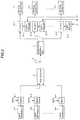
- Fig. 2 is a block diagram of another embodiment of the present invention.
- the equivalent parts to those shown in Figs. 1 and 3 are designated as the same reference numerals. Therefore different parts from those of the first embodiment are described.
- Controllers 21-1 to 21-n for controlling the respective wavelength selection characteristics of the wavelength variable filters 31-1 to 31-n are actuated by external channel selection control signals (S1 to Sn), respectively.
- Each of the optical detectors 7-1 to 7-n is not required to have a filter function for selectively extracting the superimposing frequency S1 to Sn as the channel information compared with the embodiment shown in Fig. 1.
- This embodiment uses the optical detector which is similar to that of the prior art shown in Fig. 3.
- a control signal (Si) corresponding to the channel i is input to the controller 21-1 to 21-n.
- the controllers 21-1 to 21-n have recorded the wavelength selection characteristics corresponding to the respective selection control signals (S1 to Sn). For example, the control signal (fi) is input, the controller is so constructed to control to set the wavelength selection characteristic of the variable filter 31-1 to ⁇ i.
- the rest of the controllers 21-2 to 22-n likewise control the wavelength selection characteristics of the variable filters 31-2 to 31-n, respectively in accordance with the control signals as the external channel information.
- the modulated channel information is superimposed on the signal light wavelength for transmission.
- the reception section is allowed to select a signal light of any wavelength in accordance with the channel information, leading to improved freedom in selection and wider range of use.
- modulating the signal light also provides an additional effect of inhibiting an adverse action of SBS (Stimulated Brilouin Scattering) owing to a non-linearity of the optical fiber on the transmission path.
- SBS Stimulated Brilouin Scattering
Landscapes
- Engineering & Computer Science (AREA)
- Computer Networks & Wireless Communication (AREA)
- Signal Processing (AREA)
- Optical Communication System (AREA)
Applications Claiming Priority (2)
| Application Number | Priority Date | Filing Date | Title |
|---|---|---|---|
| JP202646/95 | 1995-08-09 | ||
| JP7202646A JPH0951324A (ja) | 1995-08-09 | 1995-08-09 | 波長多重光伝送システム |
Publications (2)
| Publication Number | Publication Date |
|---|---|
| EP0758169A2 true EP0758169A2 (de) | 1997-02-12 |
| EP0758169A3 EP0758169A3 (de) | 1999-02-10 |
Family
ID=16460800
Family Applications (1)
| Application Number | Title | Priority Date | Filing Date |
|---|---|---|---|
| EP96112829A Withdrawn EP0758169A3 (de) | 1995-08-09 | 1996-08-08 | Übertragungssystem und Übertragungsverfahren mit Wellenlängenmultiplexen |
Country Status (3)
| Country | Link |
|---|---|
| US (1) | US5956166A (de) |
| EP (1) | EP0758169A3 (de) |
| JP (1) | JPH0951324A (de) |
Cited By (7)
| Publication number | Priority date | Publication date | Assignee | Title |
|---|---|---|---|---|
| WO1999035775A1 (en) * | 1998-01-09 | 1999-07-15 | Osicom Technologies, Inc. | Short distance dense wavelength division multiplexing optical communication system |
| WO1999060731A1 (en) * | 1998-05-19 | 1999-11-25 | Verifiber Technologies, Inc. | Optical surface plasmon-wave communications systems |
| ES2139538A1 (es) * | 1998-03-30 | 2000-02-01 | Consejo Superior Investigacion | Sistema de multiplexacion y transmision de señales ultrasonicas mediante fibra optica. |
| CN1082753C (zh) * | 1997-03-05 | 2002-04-10 | 富士通株式会社 | 减小受激布里渊散射影响的传输波分复用信号方法和设备 |
| EP2173043A1 (de) * | 2008-10-06 | 2010-04-07 | University College Cork | Integriertes optisches Kammquellensystem und Verfahren |
| CN103957170A (zh) * | 2014-03-12 | 2014-07-30 | 中国人民解放军63680部队 | Ip传输复接器及ip传输复接、解复接的方法 |
| WO2016027132A1 (en) * | 2014-08-21 | 2016-02-25 | Telefonaktiebolaget L M Ericsson (Publ) | Methods, optical receivers and systems for receiving drifting wavelengths carried on an optical fiber from an optical transmitter |
Families Citing this family (13)
| Publication number | Priority date | Publication date | Assignee | Title |
|---|---|---|---|---|
| JPH10164024A (ja) * | 1996-12-05 | 1998-06-19 | Nec Corp | 波長多重伝送用光送信器 |
| JPH11136214A (ja) * | 1997-10-28 | 1999-05-21 | Matsushita Electric Ind Co Ltd | 波長多重光伝送システム |
| US6124957A (en) * | 1998-02-13 | 2000-09-26 | Lucent Technologies Inc. | Optical signal translator unit |
| US6400478B1 (en) | 1998-04-02 | 2002-06-04 | Sorrento Networks, Inc. | Wavelength-division-multiplexed optical transmission system with expanded bidirectional transmission capacity over a single fiber |
| US6574016B1 (en) * | 1998-11-25 | 2003-06-03 | Nortel Networks Limited | Method and apparatus for ancillary data in a wavelength division multiplexed system |
| US7209660B1 (en) * | 1999-12-29 | 2007-04-24 | Forster Energy Llc | Optical communications using heterodyne detection |
| US7146103B2 (en) * | 1999-12-29 | 2006-12-05 | Forster Energy Llc | Optical communications using multiplexed single sideband transmission and heterodyne detection |
| US7447436B2 (en) * | 1999-12-29 | 2008-11-04 | Forster Energy Llc | Optical communications using multiplexed single sideband transmission and heterodyne detection |
| EP1410543A4 (de) * | 2000-07-27 | 2006-11-08 | John W Hicks | Faseroptisches ortszugriffskomunikationssystem |
| US6795607B1 (en) * | 2000-10-11 | 2004-09-21 | Ciena Corporation | Use of tunable laser for optical performance monitoring in WDM system |
| JP4955189B2 (ja) * | 2003-03-12 | 2012-06-20 | 日本電気株式会社 | 波長分割多重伝送システム及びそのシステムに用いられる遠隔装置並びに局装置 |
| JP4740807B2 (ja) | 2006-07-25 | 2011-08-03 | 富士通株式会社 | 波長多重光伝送システムおよび波長多重光伝送方法 |
| US10318904B2 (en) | 2016-05-06 | 2019-06-11 | General Electric Company | Computing system to control the use of physical state attainment of assets to meet temporal performance criteria |
Family Cites Families (12)
| Publication number | Priority date | Publication date | Assignee | Title |
|---|---|---|---|---|
| WO1984001679A1 (en) * | 1982-10-22 | 1984-04-26 | Ericsson Telefon Ab L M | A method of transferring an additional information channel across a transmission medium |
| JPH0720095B2 (ja) * | 1988-11-16 | 1995-03-06 | 日本電信電話株式会社 | 光周波数多重伝送装置 |
| US4896934A (en) * | 1989-02-03 | 1990-01-30 | Bell Communications Research, Inc. | Broadband optical multicast switch |
| JPH02262743A (ja) * | 1989-04-03 | 1990-10-25 | Nec Corp | 光中継器 |
| EP0438155B1 (de) * | 1990-01-19 | 1997-05-02 | Canon Kabushiki Kaisha | Optische Übertragungseinrichtung |
| US5202782A (en) * | 1990-01-19 | 1993-04-13 | Canon Kabushiki Kaisha | Optical communication method and optical communication system |
| US5093743A (en) * | 1990-12-28 | 1992-03-03 | At&T Bell Laboratories | Optical packet switch |
| EP0582061A1 (de) * | 1992-06-17 | 1994-02-09 | Siemens Aktiengesellschaft | Kohärent optische Vielkanalanordnung |
| US5418782A (en) * | 1992-10-30 | 1995-05-23 | Scientific-Atlanta, Inc. | Methods and apparatus for providing virtual service selection in a multi-service communications system |
| JPH06268592A (ja) * | 1993-03-10 | 1994-09-22 | Canon Inc | 光フィルタ制御系及びそれを用いた光fdm伝送システム |
| US5612806A (en) * | 1993-07-30 | 1997-03-18 | Gte Laboratories Incorporated | Acknowledgement using subcarrier multiplexed tones |
| US5504608A (en) * | 1995-05-25 | 1996-04-02 | At&T Corp. | Adjustable filter for tuning multimode optical signals |
-
1995
- 1995-08-09 JP JP7202646A patent/JPH0951324A/ja active Pending
-
1996
- 1996-08-07 US US08/692,958 patent/US5956166A/en not_active Expired - Fee Related
- 1996-08-08 EP EP96112829A patent/EP0758169A3/de not_active Withdrawn
Cited By (10)
| Publication number | Priority date | Publication date | Assignee | Title |
|---|---|---|---|---|
| CN1082753C (zh) * | 1997-03-05 | 2002-04-10 | 富士通株式会社 | 减小受激布里渊散射影响的传输波分复用信号方法和设备 |
| US6414772B2 (en) | 1997-03-05 | 2002-07-02 | Fujitsu Limited | Method and apparatus for transmitting a wavelength division multiplexed (WDM) signal through an optical transmission line to reduce the effects of stimulated Brillouin scattering (SBS) |
| WO1999035775A1 (en) * | 1998-01-09 | 1999-07-15 | Osicom Technologies, Inc. | Short distance dense wavelength division multiplexing optical communication system |
| ES2139538A1 (es) * | 1998-03-30 | 2000-02-01 | Consejo Superior Investigacion | Sistema de multiplexacion y transmision de señales ultrasonicas mediante fibra optica. |
| WO1999060731A1 (en) * | 1998-05-19 | 1999-11-25 | Verifiber Technologies, Inc. | Optical surface plasmon-wave communications systems |
| US6282005B1 (en) | 1998-05-19 | 2001-08-28 | Leo J. Thompson | Optical surface plasmon-wave communications systems |
| EP2173043A1 (de) * | 2008-10-06 | 2010-04-07 | University College Cork | Integriertes optisches Kammquellensystem und Verfahren |
| US8488640B2 (en) | 2008-10-06 | 2013-07-16 | University College Cork | Integrated optical comb source system and method |
| CN103957170A (zh) * | 2014-03-12 | 2014-07-30 | 中国人民解放军63680部队 | Ip传输复接器及ip传输复接、解复接的方法 |
| WO2016027132A1 (en) * | 2014-08-21 | 2016-02-25 | Telefonaktiebolaget L M Ericsson (Publ) | Methods, optical receivers and systems for receiving drifting wavelengths carried on an optical fiber from an optical transmitter |
Also Published As
| Publication number | Publication date |
|---|---|
| EP0758169A3 (de) | 1999-02-10 |
| JPH0951324A (ja) | 1997-02-18 |
| US5956166A (en) | 1999-09-21 |
Similar Documents
| Publication | Publication Date | Title |
|---|---|---|
| US5956166A (en) | Wavelength division multiplexing optical transmission system and wavelength division multiplexing optical transmission method | |
| EP0798882B1 (de) | Verfahren und Vorrichting zur Überwachung und zum Korrigieren von individuellen Kanalwellenlängenparametern in einem mehrkanaligen Wellenlängenmultiplexsystem | |
| US6366379B1 (en) | Remote control device of acousto-optic tunable filter and optical transmission system containing equalizer using acousto-optic tunable filter and optical transmission system containing optical add/drop multiplexer using acousto-optic tunable filter | |
| US6134036A (en) | Add/drop multiplexer node | |
| US6271944B1 (en) | Laser wavelength control in an optical communication system | |
| US6574016B1 (en) | Method and apparatus for ancillary data in a wavelength division multiplexed system | |
| US9912407B2 (en) | Optical relay device, optical communication system, optical relay method, and storage medium | |
| JPH11514179A (ja) | 光付加/引込波長分割多重システムの改善またはそれに関する改善 | |
| US5844706A (en) | Fibre-optic communications-transmission method and intermediate repeater for use in the method | |
| US6469812B2 (en) | Method and system for identifying undesired products of non-linear optical mixing | |
| CN101453268A (zh) | 基于偏振复用技术的光学通信系统及其方法 | |
| JP3479468B2 (ja) | 波長分割多重化システムにおける光学伝送信号の光学パワーの制御方法 | |
| EP0874490A2 (de) | Optische Übertragungseinrichtung | |
| JP3527607B2 (ja) | 光制御信号伝送装置 | |
| EP1526662A3 (de) | Verfahren und Vorrichtung zur Überwachungssignalmodulation mit variablem optischem Dämpfungsglied | |
| JPH09224016A (ja) | 光強度検出装置および方法 | |
| JP2001177505A (ja) | 波長多重双方向光伝送方法および装置 | |
| JPH10209973A (ja) | 光波長多重送信回路 | |
| US7164858B2 (en) | Optical transmission system and optical transmitter used therein | |
| JP2000201106A (ja) | 光伝送システム | |
| JP3523975B2 (ja) | 光制御信号伝送装置および光制御信号受信装置 | |
| JPH0851411A (ja) | 光周波数多重光源 | |
| JP2565128B2 (ja) | 光波長多重伝送システム | |
| EP1309118A1 (de) | Wellenlängenmultiplex Lichtwellenleiternetzwerk | |
| KR100682983B1 (ko) | 다채널 광전송 시스템에서의 광 채널 다중화/역다중화장치 및 그를 이용한 광 채널 파장 안정화 장치 |
Legal Events
| Date | Code | Title | Description |
|---|---|---|---|
| PUAI | Public reference made under article 153(3) epc to a published international application that has entered the european phase |
Free format text: ORIGINAL CODE: 0009012 |
|
| AK | Designated contracting states |
Kind code of ref document: A2 Designated state(s): DE FR GB |
|
| PUAL | Search report despatched |
Free format text: ORIGINAL CODE: 0009013 |
|
| AK | Designated contracting states |
Kind code of ref document: A3 Designated state(s): DE FR GB |
|
| 17P | Request for examination filed |
Effective date: 19990315 |
|
| 17Q | First examination report despatched |
Effective date: 20030228 |
|
| STAA | Information on the status of an ep patent application or granted ep patent |
Free format text: STATUS: THE APPLICATION IS DEEMED TO BE WITHDRAWN |
|
| 18D | Application deemed to be withdrawn |
Effective date: 20030301 |