EP0760307B1 - Fahrzeuggetriebe - Google Patents
Fahrzeuggetriebe Download PDFInfo
- Publication number
- EP0760307B1 EP0760307B1 EP96113264A EP96113264A EP0760307B1 EP 0760307 B1 EP0760307 B1 EP 0760307B1 EP 96113264 A EP96113264 A EP 96113264A EP 96113264 A EP96113264 A EP 96113264A EP 0760307 B1 EP0760307 B1 EP 0760307B1
- Authority
- EP
- European Patent Office
- Prior art keywords
- output
- input
- transmission
- vehicle
- ratio
- Prior art date
- Legal status (The legal status is an assumption and is not a legal conclusion. Google has not performed a legal analysis and makes no representation as to the accuracy of the status listed.)
- Expired - Lifetime
Links
- 230000005540 biological transmission Effects 0.000 title claims description 66
- 239000012530 fluid Substances 0.000 claims description 10
- 238000000034 method Methods 0.000 description 4
- 238000005553 drilling Methods 0.000 description 3
- 238000002485 combustion reaction Methods 0.000 description 2
- 230000000712 assembly Effects 0.000 description 1
- 238000000429 assembly Methods 0.000 description 1
- 238000010276 construction Methods 0.000 description 1
- 230000001419 dependent effect Effects 0.000 description 1
- 238000005259 measurement Methods 0.000 description 1
Images

Classifications
-
- B—PERFORMING OPERATIONS; TRANSPORTING
- B60—VEHICLES IN GENERAL
- B60K—ARRANGEMENT OR MOUNTING OF PROPULSION UNITS OR OF TRANSMISSIONS IN VEHICLES; ARRANGEMENT OR MOUNTING OF PLURAL DIVERSE PRIME-MOVERS IN VEHICLES; AUXILIARY DRIVES FOR VEHICLES; INSTRUMENTATION OR DASHBOARDS FOR VEHICLES; ARRANGEMENTS IN CONNECTION WITH COOLING, AIR INTAKE, GAS EXHAUST OR FUEL SUPPLY OF PROPULSION UNITS IN VEHICLES
- B60K17/00—Arrangement or mounting of transmissions in vehicles
- B60K17/04—Arrangement or mounting of transmissions in vehicles characterised by arrangement, location or kind of gearing
- B60K17/06—Arrangement or mounting of transmissions in vehicles characterised by arrangement, location or kind of gearing of change-speed gearing
- B60K17/08—Arrangement or mounting of transmissions in vehicles characterised by arrangement, location or kind of gearing of change-speed gearing of mechanical type
-
- F—MECHANICAL ENGINEERING; LIGHTING; HEATING; WEAPONS; BLASTING
- F16—ENGINEERING ELEMENTS AND UNITS; GENERAL MEASURES FOR PRODUCING AND MAINTAINING EFFECTIVE FUNCTIONING OF MACHINES OR INSTALLATIONS; THERMAL INSULATION IN GENERAL
- F16H—GEARING
- F16H3/00—Toothed gearings for conveying rotary motion with variable gear ratio or for reversing rotary motion
- F16H3/02—Toothed gearings for conveying rotary motion with variable gear ratio or for reversing rotary motion without gears having orbital motion
- F16H3/08—Toothed gearings for conveying rotary motion with variable gear ratio or for reversing rotary motion without gears having orbital motion exclusively or essentially with continuously meshing gears, that can be disengaged from their shafts
- F16H3/087—Toothed gearings for conveying rotary motion with variable gear ratio or for reversing rotary motion without gears having orbital motion exclusively or essentially with continuously meshing gears, that can be disengaged from their shafts characterised by the disposition of the gears
- F16H3/093—Toothed gearings for conveying rotary motion with variable gear ratio or for reversing rotary motion without gears having orbital motion exclusively or essentially with continuously meshing gears, that can be disengaged from their shafts characterised by the disposition of the gears with two or more countershafts
-
- F—MECHANICAL ENGINEERING; LIGHTING; HEATING; WEAPONS; BLASTING
- F16—ENGINEERING ELEMENTS AND UNITS; GENERAL MEASURES FOR PRODUCING AND MAINTAINING EFFECTIVE FUNCTIONING OF MACHINES OR INSTALLATIONS; THERMAL INSULATION IN GENERAL
- F16H—GEARING
- F16H3/00—Toothed gearings for conveying rotary motion with variable gear ratio or for reversing rotary motion
- F16H3/02—Toothed gearings for conveying rotary motion with variable gear ratio or for reversing rotary motion without gears having orbital motion
- F16H3/08—Toothed gearings for conveying rotary motion with variable gear ratio or for reversing rotary motion without gears having orbital motion exclusively or essentially with continuously meshing gears, that can be disengaged from their shafts
- F16H3/087—Toothed gearings for conveying rotary motion with variable gear ratio or for reversing rotary motion without gears having orbital motion exclusively or essentially with continuously meshing gears, that can be disengaged from their shafts characterised by the disposition of the gears
- F16H3/093—Toothed gearings for conveying rotary motion with variable gear ratio or for reversing rotary motion without gears having orbital motion exclusively or essentially with continuously meshing gears, that can be disengaged from their shafts characterised by the disposition of the gears with two or more countershafts
- F16H2003/0935—Toothed gearings for conveying rotary motion with variable gear ratio or for reversing rotary motion without gears having orbital motion exclusively or essentially with continuously meshing gears, that can be disengaged from their shafts characterised by the disposition of the gears with two or more countershafts with multiple countershafts comprising only one idle gear and one gear fixed to the countershaft
-
- F—MECHANICAL ENGINEERING; LIGHTING; HEATING; WEAPONS; BLASTING
- F16—ENGINEERING ELEMENTS AND UNITS; GENERAL MEASURES FOR PRODUCING AND MAINTAINING EFFECTIVE FUNCTIONING OF MACHINES OR INSTALLATIONS; THERMAL INSULATION IN GENERAL
- F16H—GEARING
- F16H2200/00—Transmissions for multiple ratios
- F16H2200/0017—Transmissions for multiple ratios specially adapted for four-wheel-driven vehicles
-
- F—MECHANICAL ENGINEERING; LIGHTING; HEATING; WEAPONS; BLASTING
- F16—ENGINEERING ELEMENTS AND UNITS; GENERAL MEASURES FOR PRODUCING AND MAINTAINING EFFECTIVE FUNCTIONING OF MACHINES OR INSTALLATIONS; THERMAL INSULATION IN GENERAL
- F16H—GEARING
- F16H37/00—Combinations of mechanical gearings, not provided for in groups F16H1/00 - F16H35/00
- F16H37/02—Combinations of mechanical gearings, not provided for in groups F16H1/00 - F16H35/00 comprising essentially only toothed or friction gearings
- F16H37/04—Combinations of toothed gearings only
- F16H37/042—Combinations of toothed gearings only change gear transmissions in group arrangement
- F16H37/046—Combinations of toothed gearings only change gear transmissions in group arrangement with an additional planetary gear train, e.g. creep gear, overdrive
-
- Y—GENERAL TAGGING OF NEW TECHNOLOGICAL DEVELOPMENTS; GENERAL TAGGING OF CROSS-SECTIONAL TECHNOLOGIES SPANNING OVER SEVERAL SECTIONS OF THE IPC; TECHNICAL SUBJECTS COVERED BY FORMER USPC CROSS-REFERENCE ART COLLECTIONS [XRACs] AND DIGESTS
- Y10—TECHNICAL SUBJECTS COVERED BY FORMER USPC
- Y10T—TECHNICAL SUBJECTS COVERED BY FORMER US CLASSIFICATION
- Y10T74/00—Machine element or mechanism
- Y10T74/19—Gearing
- Y10T74/19019—Plural power paths from prime mover
-
- Y—GENERAL TAGGING OF NEW TECHNOLOGICAL DEVELOPMENTS; GENERAL TAGGING OF CROSS-SECTIONAL TECHNOLOGIES SPANNING OVER SEVERAL SECTIONS OF THE IPC; TECHNICAL SUBJECTS COVERED BY FORMER USPC CROSS-REFERENCE ART COLLECTIONS [XRACs] AND DIGESTS
- Y10—TECHNICAL SUBJECTS COVERED BY FORMER USPC
- Y10T—TECHNICAL SUBJECTS COVERED BY FORMER US CLASSIFICATION
- Y10T74/00—Machine element or mechanism
- Y10T74/19—Gearing
- Y10T74/19023—Plural power paths to and/or from gearing
- Y10T74/19051—Single driven plural drives
- Y10T74/19056—Parallel
Definitions
- This invention relates to a transmission for a vehicle, for interposition between a prime mover of the vehicle and ground-engaging means of the vehicle and providing a plurality of gear ratios by which the ground-engaging means can be driven by the prime mover.
- a transmission in accordance with the invention has been devised primarily, although not exclusively, for a vehicle such as a tractor or loader type of vehicle for industrial and/or agricultural use, for example a vehicle of the kind commonly known as a "back-hoe loader", and in such a vehicle the ground-engaging means comprises wheels.
- the invention is also applicable to vehicles in which the ground-engaging means comprises crawler tracks.
- Vehicles such as tractors or loaders conventionally have utilised transmissions which provide a relatively small number of different gear ratios, for example four ratios. Since the ratios have to cope with drive requirements of the vehicle both on the farm or industrial site and also when the vehicle is being driven on the road, the limited number of ratios means that such vehicles may have a relatively low top road speed. It has been proposed to provide such vehicles with an additional drive line which enables a further gear ratio to be provided, the further drive line not including a torque converter which is included in the main drive line of the vehicle. This is disclosed in International Patent Application Publication No. W089/01100. There is an interlock which prevents simultaneous connection of drive by way of the multi-ratio transmission and the independent drive line. An automatic transmission with an epicyclic overdrive is disclosed in US 4056990.
- a vehicle transmission comprising:
- Said means operable to provide a driving connection between said further input and said output may include a common gear which also provides a said driving connection between said first input and said output.
- Said common gear may mesh with a further gear which is drivingly connectable by a clutch to said further input and the common gear may be drivingly connectable by a clutch to said first input.
- the driving connection between the further input and output of the transmission preferably but not exclusively, relates to an overdrive transmission ratio.
- the operating parameter of the vehicle in accordance with which a driving connection is established between the first input and the output or the further input and the output is a speed parameter.
- it comprises the vehicle speed, which conveniently may be derived from a sensor for the speed of the output of the transmission.
- Said driving connection between said further input and said output may, as in accordance with the first aspect of the invention, be by way of a part of said multi-ratio transmission means. Preferably it is not by way of at least a further part of said multi-ratio transmission means.
- the first input is connected to the prime mover of the vehicle by way of a torque convertor whilst the further input is connected to the prime mover of the vehicle without the operative interposition of such a torque convertor (although it will be appreciated that a mechanical connection between the further input and prime mover might involve a part or parts of the torque convertor, for example the casing thereof which has a non-slipping connection to the output of the prime mover).
- the transmission is one in which the driving connections between the first input and the output, and between the further input and the output, are provided by engagement of a selected one or ones of a number of fluid-pressure operable clutches in the transmission, application of fluid pressure to the appropriate clutch(es) being by way of the operation of electrically controlled valve means whose operation is determined by a suitable electrical control circuit.
- the electrical control circuit includes driver-operable switch means for controlling selection of the gear ratios in the multi-ratio transmission means, and switch means operable automatically, in accordance with said speed parameter, when the switch means relating to the highest gear ratio of the multi-ratio transmission means has been selected.
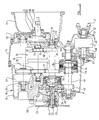
- One of the casing parts, indicated at 11, includes a portion 12 which is generally in the form of a bell-housing for connection to a prime mover in the form of an internal combustion engine E.
- the casing portion 11 forms one end of the casing of the transmission; the opposite end of the casing is afforded by a casing portion 13 and there is an intermediate casing portion 14.
- An input shaft 15 is supported in taper roller bearings 16, 17 in the casing portions 14, 13 respectively.
- the input shaft 15 protrudes through the casing portion 11 into the bell-housing portion 12 thereof, ending in a splined portion 18 for engagement with the output member of a torque convertor C, disposed within the bell housing portion 12 and whose input is connected to an output, such as the crankshaft, of the internal combustion engine E.
- an input sleeve 19 which has a splined end portion 20 for torque transmitting connection to a member such as the casing A of the torque convertor C which provides a direct driving (i.e. non-slipping) connection with the output of the prime mover.
- the input sleeve has a gear 21.
- An output shaft 22 is supported in the casing portion 13, in taper roller bearings 23, 24. Outside the casing portion 13, the output shaft 22 has an output drive flange 25 secured thereto, for connection with further drive line components leading to a ground-engaging means of the vehicle. In the example herein described, such components may be a differential gearing and/or one or more universally jointed drive shafts, for connection to a pair of road wheels of a vehicle.
- the output shaft 22 has a portion in the form of an output gear 26, and within the output gear 26 there is supported in a bearing 27 one end of a main shaft 28. The other end of the main shaft 28 is carried by a bearing 29 in the casing portion 14.
- the end of the main shaft 28 adjacent the output gear 26 carries a clutch assembly 30 which is a multi-plate hydraulically operable clutch assembly whereby a torque-transmitting connection can be established between the main shaft 28 and the output gear 26.
- the clutch assembly 30 is generally conventional in its construction and will not therefore be described in detail herein; it comprises a plurality of interleaved annular plates respectively rotationally fast with a clutch drum and a clutch hub which in turn are rotationally fast with the main shaft 28 and output gear 26, respectively.
- the plates are arranged to be brought into frictional torque-transmitting connection with one another when the clutch is supplied with hydraulic fluid under pressure, such fluid being introduced by way of a drilling down the centre of the main shaft and operating a piston incorporated in the clutch assembly.
- Hydraulic fluid is introduced to such drilling by way of an annular groove on the exterior of the opposite end of the main shaft, as indicated at 31, the groove 31 lying between two rotary seals 32 and the hydraulic fluid being introduced to the region between the seals by way of a passage 33.
- Such supply of hydraulic fluid is under the control of a solenoid valve as described hereafter.
- the input shaft 15 carries a forward clutch assembly indicated generally at 34.
- the clutch assembly 34 comprises two clutches each of which is generally as the clutch assembly 30 and which respectively provide for clutching of gears 35, 36 to the input shaft 15.
- the gears 35, 36 mesh respectively with gears 37, 38 on the main shaft 28, so that the main shaft can be driven from the input shaft at a gear ratio dependent on which of the clutches in the clutch assembly 34 is engaged to drive either the gear 35 or the gear 36.
- the clutches in the clutch assembly 34 are individually hydraulic fluid pressure operated, and indicated generally at 39 is an arrangement of two annular grooves between rotary seals, for feeding hydraulic fluid to the appropriate clutch by way of drillings extending longitudinally of the input shaft 15.
- a layshaft 40 is supported by bearings 41,42 in the casing parts 13, 14.
- the lay shaft is provided with a gear 43 which meshes with the output gear 26, and carries at an intermediate position a gear 44 which is rotatably supported on the layshaft but is able to be clutched thereto by a clutch assembly 45, the clutch assembly 45 being substantially identical to the clutch assembly 30 and operable in like manner.
- the gear 44 meshes with the gear 37 on the main shaft.
- the layshaft also non-rotatably carries a gear 46.
- the gear 46 meshes with a further gear 47 supported on an additional output shaft 48 and able to be clutched thereto by a clutch assembly 49 which once again is of the type above described.
- the shaft 48 supported in bearings 50, 51, extends out of an additional casing portion 52 and carries a drive member 53 for connection, by way of other drive line components such as universally jointed shafts and so on, to further drivable wheels of the vehicle.
- the output at the drive member 53 would be brought into use, by engagement of the clutch assembly 49, only when the vehicle is required to be used in "four-wheel drive” mode, the vehicle normally being used with two wheels only driven from the output shaft 22.
- the gear 21 on the additional input sleeve 19 meshes with a gear 55 fast on the end of a shaft 56 supported in bearings 57, 58.
- a gear 59 is able to be clutched to the shaft 56 by a further clutch assembly 60 which also is of the hydraulic pressure operable type above described.
- the gear 59 meshes with the gear 35.
- the transmission above described thus enables a first drive path to be established between the input shaft 15 and the output shaft 22 by engagement of either of the clutches in the clutch assembly 34 on the shaft 15 to the main shaft 28.
- the main shaft 28 is connectable to the output shaft 22 by either the clutch assembly 30 to give a direct drive or indirectly by way of the gear 44 and the clutch assembly 45 on the layshaft 40, gear 43, and output gear 26, to the output shaft 22.
- a multi-ratio transmission means is provided having a total of four selectable gear ratios, and each of these is by way of the torque convertor.
- neither of the clutches in the clutch assembly 34 may be engaged and the clutch 60 may be engaged to provide a further gear ratio as a result of a second drive path between the additional input sleeve 19 and the output shaft 22 via the main shaft 28 and clutch assembly 30.
- the input sleeve 19 is connected to the casing of the torque convertor, a direct (i.e. non-slipping) driving connection is established between the prime mover of the vehicle and the wheels thereof, at the further gear ratio which preferably is a higher gear ratio then the highest selectable gear ratio available by way of the torque convertor.
- the gears 35 and 37 are common gears to both drive paths.
- the second drive path from the input means 19 to the output shaft 22 includes a part of the multi-ratio transmission means, but omits a further part thereof.
- the transmission is additionally provided with an output speed sensor.
- This may be a magnetic sensor or any other appropriate type of sensor, mounted in the casing of the transmission and having a sensing portion disposed in proximity to the periphery of the output gear 26 to provide a direct measurement of the output speed of the transmission and thus of the road speed of the vehicle.
- FIG. 2 the power supply of a vehicle is indicated at 90 and ground or earth, e.g. the chassis of the vehicle or wiring provided thereon, at 91.
- a gear selector switch 101 Connected to the power supply 90 is a gear selector switch 101 which is operable between four positions under the control of the driver of the vehicle to energise appropriate solenoid valves to engage the appropriate ones of the clutch assemblies 30, 34 and 45 to provide the required one of the four available gear ratios.
- One only of such solenoid valves is indicated at 105 this being the solenoid valve which provides the highest gear ratio of the four available ratios.
- a transmission speed sensor 102 which measures the speed of the output gear 26 and thus of the output shaft 22.
- the speed signal derived from the sensor 102 is sent to a switching unit 103 which, in accordance with the speed, controls a relay 104.
- the relay 104 switches between the fourth speed solenoid valve 105 and a fifth speed solenoid valve 106 which causes the drive path to be established by way of the clutch assembly 60 to provide a fifth, overdrive, gear ratio between the casing of the torque convertor and the output shaft.
- the method of operation is as follows.
- the fourth speed solenoid valve 105 is energised and the appropriate clutches engaged to afford the fourth gear ratio.
- the switching unit 103 causes the relay 104 to be energised and switch electrical power from the fourth speed solenoid 105 to the fifth speed solenoid 106.
- a predetermined value e.g. 1500 rpm
- the switching unit 103 causes the relay 104 to be de-energised.
- the fifth speed solenoid 106 is de-energised and the fourth speed solenoid 105 re-energised, causing the transmission to revert to fourth gear.
- the transmission and control method described above has several advantages. It can make use of an existing gear selector switch 101, and provide for automatic changing between fourth and fifth gears in accordance with vehicle speed. Fifth gear can only engage after fourth gear has been selected by the driver of the vehicle. It is not possible to stall the engine of the vehicle because fifth speed direct drive reverts to fourth speed by way of the torque convertor automatically when the engine speed falls below, e.g. 1400 rpm. Additionally, the sensor 102 can be used as a speed sensor for an electronically operated vehicle speed indicator.
Landscapes
- Engineering & Computer Science (AREA)
- Mechanical Engineering (AREA)
- General Engineering & Computer Science (AREA)
- Chemical & Material Sciences (AREA)
- Combustion & Propulsion (AREA)
- Transportation (AREA)
- Control Of Transmission Device (AREA)
- Structure Of Transmissions (AREA)
- Transmission Devices (AREA)
Claims (11)
- Fahrzeuggetriebe, mit:einem ersten Eingang (15) zur Verbindung mit einem Hauptantrieb des Fahrzeugs;einem Ausgang (22) zur Verbindung mit mit dem Boden in Eingriff kommenden Rädern des Fahrzeugs;einer Getriebeeinrichtung (36, 38, 34, 28, 35, 37, 30, 44, 40, 43) mit mehreren Verhältnissen, die so wirkt, daß eine Antriebsverbindung bei einem ausgewählten Getriebeverhältnis aus einer Anzahl von Getriebeverhältnissen zwischen dem ersten Eingang und dem Ausgang (22) hergestellt wird;einem weiteren Eingang (19) zur Verbindung mit dem Hauptantrieb des Fahrzeugs;einem Mittel (60), das so wirkt, daß eine Antriebsverbindung zwischen dem weiteren Eingang (19) und dem Ausgang (22) über zumindest einen Teil (35, 37) der genannten Getriebeeinrichtung mit mehreren Verhältnissen hergestellt wird, wobei die Antriebsverbindung zwischen dem weiteren Eingang (19) und dem Ausgang (22) des Getriebes ein größeres Übersetzungsverhältnis als das größte Übersetzungsverhältnis bereitstellt, das durch die Getriebeeinrichtung mit mehreren Verhältnissen zwischen dem ersten Eingang (15) des Getriebes und dem Ausgang (22) bereitgestellt wird, dadurch gekennzeichnet, daß die Getriebeeinrichtung mit mehreren Verhältnissen so wirkt, daß ein erforderliches Verhältnis unter der Kontrolle eines Fahrers des Fahrzeugs ausgewählt wird, während das Mittel, das eine Antriebsverbindung zwischen dem weiteren Eingang (19) und dem Ausgang (22) bereitstellt, so eingerichtet ist, daß es in Betrieb genommen wird, und wobei die Antriebsverbindung zwischen dem ersten Eingang (15) und dem Ausgang (22) nur dann unterbrochen wird, wenn der Fahrer das größte Übersetzungsverhältnis der Getriebeeinrichtung mit mehreren Verhältnissen ausgewählt hat.
- Getriebe nach Anspruch 1, dadurch gekennzeichnet, daß das Mittel, das so wirkt, daß eine Antriebsverbindung zwischen dem weiteren Eingang (19) und dem Ausgang (22) hergestellt wird, ein gemeinsames Zahnrad (35) aufweist, das auch eine Antriebsverbindung zwischen dem ersten Eingang (15) und dem Ausgang (22) herstellt.
- Getriebe nach Anspruch 2, dadurch gekennzeichnet daß das gemeinsame Zahnrad (35) mit einem weiteren Zahnrad (59) in Eingriff steht, das durch eine Kupplung (60) in Antriebsverbindung mit dem weiteren Eingang (19) bringbar ist, wobei das gemeinsame Zahnrad (35) durch eine Kupplung (34) mit dem ersten Eingang (15) in Antriebsverbindung bringbar ist.
- Getriebe nach einem der Ansprüche 1 bis 3, gekennzeichnet durch Mittel (102, 103), die gemäß einer Erfassungseinrichtung (102) für einen Betriebsparameter des Fahrzeugs selektiv betätigbar sind, um eine Antriebsverbindung entweder zwischen dem ersten Eingang (15) und dem Ausgang (22) oder dem weiteren Eingang (19) und dem Ausgang (22) herzustellen.
- Getriebe nach Anspruch 4, dadurch gekennzeichnet, daß der Betriebsparameter des Fahrzeugs, gemäß dem eine Antriebsverbindung zwischen dem ersten Eingang (15) und dem Ausgang (22) oder dem weiteren Eingang (19) und dem Ausgang (22) hergestellt wird, ein Geschwindigkeitsparameter ist.
- Getriebe nach Anspruch 5, dadurch gekennzeichnet, daß der Geschwindigkeitsparameter die Fahrzeuggeschwindigkeit ist, die von einem Sensor (102) für die Drehzahl des Ausgangs (26) des Getriebes abgeleitet wird.
- Getriebe nach einem der vorangehenden Ansprüche, dadurch gekennzeichnet, daß die Antriebsverbindung zwischen dem weiteren Eingang (19) und dem Ausgang (22) auf andere Weise als durch ein weiteres Teil (34, 36, 38) der Getriebeeinrichtung mit mehreren Verhältnissen bereitgestellt wird.
- Getriebe nach einem der vorangehenden Ansprüche, dadurch gekennzeichnet, daß der erste Eingang (15) mit dem Hauptantrieb des Fahrzeugs durch einen Drehmomentwandler verbunden ist, während der weitere Eingang (19) mit dem Hauptantrieb des Fahrzeugs ohne die operative Einschaltung eines Drehmomentwandlers verbunden ist.
- Getriebe nach einem der vorangehenden Ansprüche, dadurch gekennzeichnet, daß Antriebsverbindungen zwischen dem ersten Eingang (19) und dem Ausgang (22) und zwischen dem weiteren Eingang (19) und dem Ausgang (22) durch Eingriff einer oder einer Anzahl von mittels Fluiddruck betätigbarer Kupplungen (30, 34, 35, 60) in dem Getriebe hergestellt werden.
- Getriebe nach Anspruch 9, dadurch gekennzeichnet, daß eine Aufbringung von Fluiddruck auf eine entsprechende Kupplung uber die Betätigung von elektrisch kontrollierten Ventileinrichtungen (105, 106) erfolgt, deren Betätigung durch eine elektrische Steuerschaltung festgelegt wird.
- Getriebe nach Anspruch 10, soweit abhängig von Anspruch 7, dadurch gekennzeichnet, daß die elektrische Steuerschaltung vom Fahrer betätigbare Schalteinrichtungen (103) aufweist, um die Auswahl der Übersetzungsverhältnisse in der Getriebeeinrichtung mit mehreren Verhältnissen zu kontrollieren, und automatisch betätigbare Schalteinrichtungen, gemäß dem genannten Geschwindigkeitsparameter, wenn die Schalteinrichung (103), die sich auf das größte Übersetzungsverhältnis der Getriebeeinrichtung mit mehreren Verhältnissen bezieht, ausgewählt worden ist.
Applications Claiming Priority (2)
| Application Number | Priority Date | Filing Date | Title |
|---|---|---|---|
| GB9517582 | 1995-08-26 | ||
| GBGB9517582.4A GB9517582D0 (en) | 1995-08-26 | 1995-08-26 | Vehicle transmission |
Publications (3)
| Publication Number | Publication Date |
|---|---|
| EP0760307A2 EP0760307A2 (de) | 1997-03-05 |
| EP0760307A3 EP0760307A3 (de) | 1997-11-26 |
| EP0760307B1 true EP0760307B1 (de) | 2001-03-14 |
Family
ID=10779863
Family Applications (1)
| Application Number | Title | Priority Date | Filing Date |
|---|---|---|---|
| EP96113264A Expired - Lifetime EP0760307B1 (de) | 1995-08-26 | 1996-08-19 | Fahrzeuggetriebe |
Country Status (6)
| Country | Link |
|---|---|
| US (1) | US5782144A (de) |
| EP (1) | EP0760307B1 (de) |
| DE (1) | DE69612044T2 (de) |
| ES (1) | ES2156241T3 (de) |
| GB (2) | GB9517582D0 (de) |
| PT (1) | PT760307E (de) |
Families Citing this family (2)
| Publication number | Priority date | Publication date | Assignee | Title |
|---|---|---|---|---|
| GB2463911B (en) | 2008-09-30 | 2012-06-06 | Jcb Transmissions | Vehicle transmission |
| US11613177B2 (en) | 2020-10-28 | 2023-03-28 | Deere & Company | Drop-box transmission in a reduced space |
Family Cites Families (27)
| Publication number | Priority date | Publication date | Assignee | Title |
|---|---|---|---|---|
| US2704468A (en) * | 1955-03-22 | Power transmission | ||
| US2943515A (en) * | 1959-02-12 | 1960-07-05 | Int Harvester Co | Power transmitting apparatus |
| US3400609A (en) * | 1965-10-23 | 1968-09-10 | Gen Motors Corp | Transmission |
| DE1655894A1 (de) * | 1966-02-22 | 1970-03-05 | Zahnradfabrik Friedrichshafen | Antriebsanlage fuer Kraftfahrzeuge,insbesondere fuer landwirtschaftliche Nutzfahrzeuge |
| US3446094A (en) * | 1966-06-20 | 1969-05-27 | Nissan Motor | Torque split-type automatic speed change device |
| US3557635A (en) * | 1968-11-06 | 1971-01-26 | Gen Motors Corp | Transmission with phasing clutch for torque converter rotor |
| SU493380A1 (ru) * | 1971-08-20 | 1975-11-28 | Центральный Ордена Трудового Красного Знамени Научно-Исследовательский Автомобильный И Автомоторный Институт | Гидромеханическа передача |
| JPS5645022B2 (de) * | 1975-01-23 | 1981-10-23 | ||
| US3982599A (en) * | 1975-02-21 | 1976-09-28 | Deere & Company | Tractor having transmission-driven power take-off |
| JPS53140465A (en) * | 1977-05-13 | 1978-12-07 | Nissan Motor Co Ltd | Transmission |
| EP0040864B1 (de) * | 1978-03-06 | 1986-05-28 | Eaton Corporation | Leistungsschaltgetriebe |
| EP0004045B2 (de) * | 1978-03-06 | 1985-07-31 | Eaton Corporation | Schaltgetriebe |
| DE2830543A1 (de) * | 1978-07-12 | 1980-01-24 | Volkswagenwerk Ag | Hydrodynamisch-mechanisches getriebe fuer kraftfahrzeuge |
| DE2842390A1 (de) * | 1978-09-29 | 1980-04-17 | Bosch Gmbh Robert | Elektronische schaltvorrichtung fuer die betaetigung eines overdrives |
| GB2078318A (en) * | 1980-06-24 | 1982-01-06 | Automotive Prod Co Ltd | Rotary change-speed transmission |
| US4462276A (en) * | 1980-09-09 | 1984-07-31 | Fuji Jukogyo Kabushiki Kaisha | Control system for automatic transmission with overdrive device |
| JPS5761844A (en) * | 1980-09-09 | 1982-04-14 | Fuji Heavy Ind Ltd | Automatic transmission gear with over drive |
| US4495837A (en) * | 1981-12-16 | 1985-01-29 | Eaton Corporation | Trimmer valve |
| JPS58221061A (ja) * | 1982-06-18 | 1983-12-22 | Toyota Motor Corp | 歯車式変速装置 |
| EP0110538A3 (de) * | 1982-11-04 | 1985-07-31 | Eaton Corporation | Automatisches Getriebe mit erweitertem Gebiet der Übersetzverhältnisse |
| JPH0765656B2 (ja) * | 1985-02-12 | 1995-07-19 | 株式会社大金製作所 | オートマチックトランスミッション |
| US4872374A (en) * | 1985-07-03 | 1989-10-10 | Rockwell International Corporation | Planetary transmission apparatus having a four element torque converter |
| US4872375A (en) * | 1985-07-03 | 1989-10-10 | Rockwell International Corporation | Control method for planetary transmission having four element torque converter |
| GB8602560D0 (en) * | 1986-02-03 | 1986-03-12 | Automotive Prod Plc | Rotary transmission |
| GB2199624B (en) * | 1987-01-09 | 1990-08-15 | Automotive Products Plc | A change speed transmission |
| GB8718027D0 (en) * | 1987-07-29 | 1987-09-03 | Massey Ferguson Mfg | Vehicle drive lines |
| DE4031571A1 (de) * | 1990-10-05 | 1992-04-09 | Daimler Benz Ag | Verfahren zum schalten eines mehrwege-zahnraederwechselgetriebes mit jeweils durch eine zahnradkupplung mit ihrer welle kuppelbaren losraedern |
-
1995
- 1995-08-26 GB GBGB9517582.4A patent/GB9517582D0/en active Pending
-
1996
- 1996-08-19 ES ES96113264T patent/ES2156241T3/es not_active Expired - Lifetime
- 1996-08-19 DE DE69612044T patent/DE69612044T2/de not_active Expired - Fee Related
- 1996-08-19 PT PT96113264T patent/PT760307E/pt unknown
- 1996-08-19 GB GB9617394A patent/GB2304834B/en not_active Expired - Fee Related
- 1996-08-19 EP EP96113264A patent/EP0760307B1/de not_active Expired - Lifetime
- 1996-08-20 US US08/700,226 patent/US5782144A/en not_active Expired - Fee Related
Also Published As
| Publication number | Publication date |
|---|---|
| ES2156241T3 (es) | 2001-06-16 |
| EP0760307A2 (de) | 1997-03-05 |
| US5782144A (en) | 1998-07-21 |
| PT760307E (pt) | 2001-08-30 |
| EP0760307A3 (de) | 1997-11-26 |
| DE69612044T2 (de) | 2001-07-19 |
| GB9517582D0 (en) | 1995-11-01 |
| DE69612044D1 (de) | 2001-04-19 |
| GB9617394D0 (en) | 1996-10-02 |
| GB2304834A (en) | 1997-03-26 |
| GB2304834B (en) | 1999-05-12 |
Similar Documents
| Publication | Publication Date | Title |
|---|---|---|
| US11945293B2 (en) | Dual motor electric driveline | |
| US8105203B2 (en) | Dual clutch transmission | |
| EP0153196B1 (de) | Getriebeanlage mit Zapfwellen für Motorfahrzeuge | |
| CA2792429C (en) | Integrated transmission and auxiliary gearbox control | |
| US8250938B2 (en) | Vehicle transmission | |
| EP1660789B1 (de) | Hydromechanisches getriebe für landwirtschaftstraktoren | |
| EP1908996B1 (de) | Verfahren zur Steuerung eines Fahrzeuggetriebes | |
| EP0753688A1 (de) | Verfahren zur steuerung eines mechanisch-hydraulischen getriebes | |
| EP1908997B1 (de) | Verfahren zur Steuerung eines Fahrzeuggetriebes | |
| US6139458A (en) | Hydrostatic/direct drive transmission system and associated method | |
| US5782144A (en) | Vehicle transmission | |
| CN100558576C (zh) | 用于车辆传动系统的驱动系统以及包括该驱动系统的车辆 | |
| EP1172247B1 (de) | Schaltvorrichtung für hohe Fahrzeuggeschwindigkeiten | |
| EP1772651A2 (de) | Getriebesteuerverfahren | |
| KR102582846B1 (ko) | 작업 차량, pto 장치 및 pto 커버 유니트 | |
| JPS61189349A (ja) | パワ−トランスミツシヨンの操作部 | |
| JPH0670469B2 (ja) | 作業車の走行変速装置 | |
| JPH0829676B2 (ja) | トラクタの変速伝動装置 |
Legal Events
| Date | Code | Title | Description |
|---|---|---|---|
| PUAI | Public reference made under article 153(3) epc to a published international application that has entered the european phase |
Free format text: ORIGINAL CODE: 0009012 |
|
| AK | Designated contracting states |
Kind code of ref document: A2 Designated state(s): CH DE ES FR IE IT LI NL PT SE |
|
| PUAL | Search report despatched |
Free format text: ORIGINAL CODE: 0009013 |
|
| AK | Designated contracting states |
Kind code of ref document: A3 Designated state(s): CH DE ES FR GB IE IT LI NL PT SE |
|
| 17P | Request for examination filed |
Effective date: 19980112 |
|
| 17Q | First examination report despatched |
Effective date: 19990428 |
|
| GRAG | Despatch of communication of intention to grant |
Free format text: ORIGINAL CODE: EPIDOS AGRA |
|
| GRAG | Despatch of communication of intention to grant |
Free format text: ORIGINAL CODE: EPIDOS AGRA |
|
| GRAH | Despatch of communication of intention to grant a patent |
Free format text: ORIGINAL CODE: EPIDOS IGRA |
|
| RBV | Designated contracting states (corrected) |
Designated state(s): CH DE ES FR IE IT LI NL PT SE |
|
| GRAH | Despatch of communication of intention to grant a patent |
Free format text: ORIGINAL CODE: EPIDOS IGRA |
|
| GRAA | (expected) grant |
Free format text: ORIGINAL CODE: 0009210 |
|
| AK | Designated contracting states |
Kind code of ref document: B1 Designated state(s): CH DE ES FR IE IT LI NL PT SE |
|
| REG | Reference to a national code |
Ref country code: CH Ref legal event code: EP |
|
| REG | Reference to a national code |
Ref country code: IE Ref legal event code: FG4D |
|
| REF | Corresponds to: |
Ref document number: 69612044 Country of ref document: DE Date of ref document: 20010419 |
|
| ET | Fr: translation filed | ||
| ITF | It: translation for a ep patent filed | ||
| REG | Reference to a national code |
Ref country code: CH Ref legal event code: NV Representative=s name: ISLER & PEDRAZZINI AG * ISLER & PEDRAZZINI AG |
|
| REG | Reference to a national code |
Ref country code: ES Ref legal event code: FG2A Ref document number: 2156241 Country of ref document: ES Kind code of ref document: T3 |
|
| PLBE | No opposition filed within time limit |
Free format text: ORIGINAL CODE: 0009261 |
|
| STAA | Information on the status of an ep patent application or granted ep patent |
Free format text: STATUS: NO OPPOSITION FILED WITHIN TIME LIMIT |
|
| 26N | No opposition filed | ||
| PGFP | Annual fee paid to national office [announced via postgrant information from national office to epo] |
Ref country code: PT Payment date: 20070629 Year of fee payment: 12 |
|
| PGFP | Annual fee paid to national office [announced via postgrant information from national office to epo] |
Ref country code: IE Payment date: 20070813 Year of fee payment: 12 |
|
| PGFP | Annual fee paid to national office [announced via postgrant information from national office to epo] |
Ref country code: DE Payment date: 20070816 Year of fee payment: 12 |
|
| PGFP | Annual fee paid to national office [announced via postgrant information from national office to epo] |
Ref country code: ES Payment date: 20070926 Year of fee payment: 12 |
|
| REG | Reference to a national code |
Ref country code: CH Ref legal event code: PCAR Free format text: ISLER & PEDRAZZINI AG;POSTFACH 1772;8027 ZUERICH (CH) |
|
| PGFP | Annual fee paid to national office [announced via postgrant information from national office to epo] |
Ref country code: CH Payment date: 20070815 Year of fee payment: 12 |
|
| PGFP | Annual fee paid to national office [announced via postgrant information from national office to epo] |
Ref country code: SE Payment date: 20070807 Year of fee payment: 12 Ref country code: NL Payment date: 20070805 Year of fee payment: 12 Ref country code: IT Payment date: 20070828 Year of fee payment: 12 |
|
| PGFP | Annual fee paid to national office [announced via postgrant information from national office to epo] |
Ref country code: FR Payment date: 20070808 Year of fee payment: 12 |
|
| REG | Reference to a national code |
Ref country code: PT Ref legal event code: MM4A Free format text: LAPSE DUE TO NON-PAYMENT OF FEES Effective date: 20090219 |
|
| REG | Reference to a national code |
Ref country code: CH Ref legal event code: PL |
|
| EUG | Se: european patent has lapsed | ||
| NLV4 | Nl: lapsed or anulled due to non-payment of the annual fee |
Effective date: 20090301 |
|
| REG | Reference to a national code |
Ref country code: IE Ref legal event code: MM4A |
|
| PG25 | Lapsed in a contracting state [announced via postgrant information from national office to epo] |
Ref country code: PT Free format text: LAPSE BECAUSE OF NON-PAYMENT OF DUE FEES Effective date: 20090219 Ref country code: NL Free format text: LAPSE BECAUSE OF NON-PAYMENT OF DUE FEES Effective date: 20090301 |
|
| REG | Reference to a national code |
Ref country code: FR Ref legal event code: ST Effective date: 20090430 |
|
| PG25 | Lapsed in a contracting state [announced via postgrant information from national office to epo] |
Ref country code: LI Free format text: LAPSE BECAUSE OF NON-PAYMENT OF DUE FEES Effective date: 20080831 Ref country code: CH Free format text: LAPSE BECAUSE OF NON-PAYMENT OF DUE FEES Effective date: 20080831 |
|
| PG25 | Lapsed in a contracting state [announced via postgrant information from national office to epo] |
Ref country code: IE Free format text: LAPSE BECAUSE OF NON-PAYMENT OF DUE FEES Effective date: 20080819 |
|
| PG25 | Lapsed in a contracting state [announced via postgrant information from national office to epo] |
Ref country code: IT Free format text: LAPSE BECAUSE OF NON-PAYMENT OF DUE FEES Effective date: 20080819 Ref country code: FR Free format text: LAPSE BECAUSE OF NON-PAYMENT OF DUE FEES Effective date: 20080901 Ref country code: DE Free format text: LAPSE BECAUSE OF NON-PAYMENT OF DUE FEES Effective date: 20090303 |
|
| REG | Reference to a national code |
Ref country code: ES Ref legal event code: FD2A Effective date: 20080820 |
|
| PG25 | Lapsed in a contracting state [announced via postgrant information from national office to epo] |
Ref country code: ES Free format text: LAPSE BECAUSE OF NON-PAYMENT OF DUE FEES Effective date: 20080820 |
|
| PG25 | Lapsed in a contracting state [announced via postgrant information from national office to epo] |
Ref country code: SE Free format text: LAPSE BECAUSE OF NON-PAYMENT OF DUE FEES Effective date: 20080820 |