EP0762399B1 - Procédé et appareil d'enregistrement/de reproduction de données optiques - Google Patents
Procédé et appareil d'enregistrement/de reproduction de données optiques Download PDFInfo
- Publication number
- EP0762399B1 EP0762399B1 EP96114553A EP96114553A EP0762399B1 EP 0762399 B1 EP0762399 B1 EP 0762399B1 EP 96114553 A EP96114553 A EP 96114553A EP 96114553 A EP96114553 A EP 96114553A EP 0762399 B1 EP0762399 B1 EP 0762399B1
- Authority
- EP
- European Patent Office
- Prior art keywords
- recording
- recording power
- recorded
- data
- optical data
- Prior art date
- Legal status (The legal status is an assumption and is not a legal conclusion. Google has not performed a legal analysis and makes no representation as to the accuracy of the status listed.)
- Expired - Lifetime
Links
- 230000003287 optical effect Effects 0.000 title claims description 120
- 238000000034 method Methods 0.000 title claims description 38
- 238000012360 testing method Methods 0.000 claims description 73
- 230000008859 change Effects 0.000 claims description 33
- 230000014509 gene expression Effects 0.000 claims description 24
- 238000004519 manufacturing process Methods 0.000 claims description 10
- 239000000463 material Substances 0.000 claims description 4
- 238000012806 monitoring device Methods 0.000 claims description 4
- 229920006395 saturated elastomer Polymers 0.000 claims description 4
- 101100077717 Mus musculus Morn2 gene Proteins 0.000 claims 2
- 238000007405 data analysis Methods 0.000 claims 1
- 230000001419 dependent effect Effects 0.000 claims 1
- 238000013213 extrapolation Methods 0.000 claims 1
- 230000000694 effects Effects 0.000 description 13
- 238000012544 monitoring process Methods 0.000 description 6
- 230000008901 benefit Effects 0.000 description 4
- 238000001514 detection method Methods 0.000 description 2
- 238000010586 diagram Methods 0.000 description 2
- 230000001678 irradiating effect Effects 0.000 description 2
- 239000004065 semiconductor Substances 0.000 description 2
- 239000000956 alloy Substances 0.000 description 1
- 229910045601 alloy Inorganic materials 0.000 description 1
- 238000011109 contamination Methods 0.000 description 1
- 238000005516 engineering process Methods 0.000 description 1
- 235000015095 lager Nutrition 0.000 description 1
- 239000002184 metal Substances 0.000 description 1
- 238000012986 modification Methods 0.000 description 1
- 230000004048 modification Effects 0.000 description 1
- 239000000049 pigment Substances 0.000 description 1
- 230000008569 process Effects 0.000 description 1
- 230000004044 response Effects 0.000 description 1
Images


Classifications
-
- G—PHYSICS
- G11—INFORMATION STORAGE
- G11B—INFORMATION STORAGE BASED ON RELATIVE MOVEMENT BETWEEN RECORD CARRIER AND TRANSDUCER
- G11B7/00—Recording or reproducing by optical means, e.g. recording using a thermal beam of optical radiation by modifying optical properties or the physical structure, reproducing using an optical beam at lower power by sensing optical properties; Record carriers therefor
- G11B7/12—Heads, e.g. forming of the optical beam spot or modulation of the optical beam
- G11B7/125—Optical beam sources therefor, e.g. laser control circuitry specially adapted for optical storage devices; Modulators, e.g. means for controlling the size or intensity of optical spots or optical traces
- G11B7/126—Circuits, methods or arrangements for laser control or stabilisation
-
- G—PHYSICS
- G11—INFORMATION STORAGE
- G11B—INFORMATION STORAGE BASED ON RELATIVE MOVEMENT BETWEEN RECORD CARRIER AND TRANSDUCER
- G11B7/00—Recording or reproducing by optical means, e.g. recording using a thermal beam of optical radiation by modifying optical properties or the physical structure, reproducing using an optical beam at lower power by sensing optical properties; Record carriers therefor
- G11B7/004—Recording, reproducing or erasing methods; Read, write or erase circuits therefor
- G11B7/0045—Recording
-
- G—PHYSICS
- G11—INFORMATION STORAGE
- G11B—INFORMATION STORAGE BASED ON RELATIVE MOVEMENT BETWEEN RECORD CARRIER AND TRANSDUCER
- G11B11/00—Recording on or reproducing from the same record carrier wherein for these two operations the methods are covered by different main groups of groups G11B3/00 - G11B7/00 or by different subgroups of group G11B9/00; Record carriers therefor
- G11B11/10—Recording on or reproducing from the same record carrier wherein for these two operations the methods are covered by different main groups of groups G11B3/00 - G11B7/00 or by different subgroups of group G11B9/00; Record carriers therefor using recording by magnetic means or other means for magnetisation or demagnetisation of a record carrier, e.g. light induced spin magnetisation; Demagnetisation by thermal or stress means in the presence or not of an orienting magnetic field
- G11B11/105—Recording on or reproducing from the same record carrier wherein for these two operations the methods are covered by different main groups of groups G11B3/00 - G11B7/00 or by different subgroups of group G11B9/00; Record carriers therefor using recording by magnetic means or other means for magnetisation or demagnetisation of a record carrier, e.g. light induced spin magnetisation; Demagnetisation by thermal or stress means in the presence or not of an orienting magnetic field using a beam of light or a magnetic field for recording by change of magnetisation and a beam of light for reproducing, i.e. magneto-optical, e.g. light-induced thermomagnetic recording, spin magnetisation recording, Kerr or Faraday effect reproducing
- G11B11/10595—Control of operating function
Definitions
- the present invention relates to an optical data recording/reproducing method and apparatus.
- the method can be enumerated in which an optimum recording power is set to each optical data recording/reproducing apparatus by monitoring an amplitude of recording signal (a difference between a level of a signal from a not-recorded section and that of a signal from a recorded section) ,which is a representative reproduced signal in an optical data recording medium, but an amplitude value of a recording signal changes according not only to a recording power, but also to a number of openings in an optical pickup, rim intensity (distribution of intensity of an incident laser beam to a focusing lens) ,a size and a form of each light spot, and contamination of the optical system associated with passage of time, and generally offset by 20 to 40% is generated between each optical pickup, so that a set value is largely displaced from the optimum one because of the effect by the offset described above.
- an amplitude of recording signal a difference between a level of a signal from a not-recorded section and that of a signal from a recorded section
- a test recording is executed in a data track and then an optimum recording power is set. After that, the test data can be erased and a new data can be recorded, or a new data can be overwritten directly in the track in which the test recording is executed. So, though a data track exclusive for testing need not be formed as the postscript type optical data recording medium, it is not prevented that the recording power of the test recording is excessively increased and the data track is damaged.
- the data track exclusive for testing need be formed, and there are disadvantages that a setting error of an optimum recording power is enlarged due to a difference of recording characteristic which is due to a position difference of each data track, or the data track exclusive for testing is in vain for a user.
- one object of the present invention is to provide an optical data recording/reproducing method and apparatus which can set an optimum recording power without an effect of offset of a recording power and/or an amplitude of recording signal.
- Another object of the present invention is to provide an optical data recording/reproducing method and apparatus which can easily set an optimum recording power with a precision acceptable in actual use in an optical data recording/reproducing apparatus designed for mass production.
- a rewritable optical disk, optical card or optical tape etc. can be cited as an optical data recording medium which can be used in the present invention , and the present invention can apply to an optical data recording/reproducing method and apparatus which executes hole opening recording or thermal change recording onto pigment, metal or alloy film, magneto-optic recording, phase change recording which changes reflection ratio or phase of light, or etc.
- a proper method for a recording medium and a recording signal can be used, for instance an irradiation method of long and short rectangular pulse lights or that of intermittence of short pulse light which is already known.
- Figure 2 shows examples of a recording light pulse used in the optical data recording/reproducing apparatus of the embodiments.
- Figure 2(a) shows an example of a data which intend to be recorded and recording sections 1 and 3, and not-recording section 2 are recorded onto a data track in the optical data recording medium.
- the data recorded onto this optical data recording medium is reproduced, and as shown in Figure 2(e) a difference between a signal level from the recording section and a signal level from the not-recording section, that is an amplitude of recording signal, is detected.
- This amplitude of the recording signal can be generated by a difference reflection ratio between the recording section and the not-recording section in the optical data recording medium or a difference of intensity of a light to which Kerr rotation angle is converted by an optical process in magneto-optic recording.
- Figure 2(b), Figure 2(c) and Figure 2(d) show representative examples of a recording light pulse which is applied to the present invention.
- the example in Figure 2(b) is most simple one where modulation is executed by corresponding a weak reproducing power Pr and a strong recording power Pw to the not-recording section and the recording section. It is suitable for recording a data onto a recording surface of low heat conduction.
- the example in Figure 2(c) is that a long recording section is recorded by a pulse train and it is suitable for recording a data onto a recording surface of high heat conduction by a constant recording width.
- the example in Figure 2(d) is one of recording pulses that records a data onto a recording surface where overwriting is possible in magneto-optic recording or phase change recording.
- a light of an erasing power Pe of middle level is continuously irradiated and therefore a not-recording section is formed.
- a recording power P and a bias power Pb are irradiated by turns and therefore an old data is erased and a new data is replaced.
- a value of g(P) is a numerical value stored irrespective of whether m and P are offset or not, and for this reason it may be said that the numerical value always and accurately indicates whether a recording power is excessive or short. Accordingly, by setting a recording power P for recording data so that the standardized gradation value g(P) will be obtained in the data recording/reproducing apparatus, even if data is recorded with a different data recording/reproducing apparatus, always data can be recorded in the same recording conditions, which is quite convenient for applications in the industrial fields where importance is put on reproductivity of recorded data.
- a value of a recording power becomes larger, a value of m is saturated and generally g (P) is converged to zero, and for this reason to more accurately detect whether a recording power is excessive or short, it is efficient to set a value of g(P) in a range from 0.2 to 2.0, more preferably in a range from 0.7 to 1.7 and get an optimum recording power by multiplying a value of P corresponding to this by a value in a range from 1.0 to 1.7, preferably in a range from 1.0 to 1.5.
- g(P) ( ⁇ m/m) ( ⁇ P/P) wherein ⁇ P is a minute change rate near P, and ⁇ m indicates a minute change rate corresponding to ⁇ P near m.
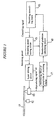
- FIG. 1 is a block diagram showing an optical data recording/reproducing apparatus of embodiments of the present invention.
- an optical data recording medium 11 such as an optical disk is driven by a driving device 12 such as a spindle motor.
- An optical source such as a semiconductor laser is driven by a laser driving circuit 14 of an optical source driving device and irradiates a light onto the optical data recording medium 11 by way of an optical system not shown in the figure, and therefore a recording/reproducing pickup 13 records and reproduces a data.
- a recording power setting circuit 15 of a recording power setting device is controlled by a recording controlling block 16 of a recording controlling device which controls overall controlling system and it sets a recording power for testing and an optimum recording power.
- the recording controlling block 16 sets the recording power for testing and the optimum recording power through the recording power setting circuit 15, the laser driving circuit 14 and the recording/reproducing pickup 13.
- the laser driving circuit 14 drives the semiconductor laser to emit at the recording power for testing or the optimum recording power which is set by the recording power setting circuit 15.
- the laser driving circuit 14 drives the laser in the recording/reproducing pickup 13 to emit at the recording power for testing P set by the recording power setting circuit 15, which changes from time to time. Also the recording/reproducing pickup 13 records a pattern of a not-recording section and a recording section onto the optical data recording medium 11 for the recording for testing as changing the recording power P from time to time and reproduces the data of the pattern therefrom.
- a monitoring circuit of amplitude of recording signal 17 which is a monitoring device of amplitude of recording signal monitors an amplitude m of recording signal corresponding to the recording power P, which is a difference between a signal level of the not-recording section and that of the recording section, from a reproducing signal which is reproduced by the recording/reproducing pickup 13.
- the recording controlling block 16 decides the optimum recording power on the basis of the standardized gradation g(P) calculated by the standardized gradation calculating circuit 18, and sets the optimum recording power in the recording power setting circuit 15.
- the laser driving circuit 14 drives the laser in the recording/reproducing pickup 13 to emit at the optimum recording power set by the recording power setting circuit 15 and the recording/reproducing pickup 13 records a data onto the optical data recording medium 11 at the optimum recording power.
- the laser driving circuit 14 drives the laser in the recording/reproducing pickup 13 to emit at a reproducing power and the recording/reproducing pickup 13 reproduces the data from the optical data recording medium 11 by a light of the reproducing power.
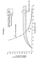
- Fig. 3 shows an example of effects provided in this embodiment of the invention.
- Relations between amplitude m of recording signal recorded and reproduced by different 3 types of data recording/reproducing apparatus and the recording power P are as shown in Fig. 3, and a saturation value of amplitude of recording signal in each case is different: 0.60, 0.75, and 0.50 respectively, so that different curves m(0) , m (1) and m (2) are provided, and in this case an uniform target of optimum recording power can not be obtained even with reference to a certain amplitude level of recording signal, and nonuniformity is generated in response to the curves m(0) ,m(1) and m(2).
- an optimum recording power can automatically be set without being affected by nonuniformity between various types of data recording/reproducing apparatus, and a low cost optical data recording/reproducing apparatus can be provided.
- the recording controlling block 16 detects a recording power Ps at which the standardized gradation g(P) coincides with the a specific value S which is selected in a range from 0.2 to 2.0, and it sets an optimum recording power to the recording power setting circuit 15 by multiplying Ps by a value in a range from 1.0 to 1.7.
- Fig. 4 shows an example of effects provided in the embodiment of the invention.
- a relation between an amplitude m of recording signal and a recording power P and a relation between a standardized gradation g and a recording power P are the same as those in the embodiment of the above invention.
- a value of the standardized gradation g itself becomes smaller, and also a change rate to P becomes smaller, so that it is easily affected by external disturbance or noise and a precision in detection of P may become lower.
- Fig. 4 shows an example of effects provided in the embodiment of the present invention in which S of the specific value is 1.0, and also this figure shows an effect provided by the method of detecting a recording power Ps at which a value of the standardized gradation g coincides with S in this embodiment.
- Ps is smaller than an actual optimum recording power Popt, so that Popt is set by multiplying this Ps by 1.20.
- the particular value of S may be selected from a range from 0.2 to 2.0 so that influence by noise will be negligible, and in this case it is possible to detect a recording power Ps corresponding to a set value S with high precision.
- Offset of a recording power Ps from the optimum recording power Popt can be checked by previously setting an appropriate value in a range from 1.0 to 1.7 times and by computing the optimum recording power Popt by multiplying Ps by this value. For this reason an optimum recording power can furthermore precisely be set.
- an optical data recording medium is repeatedly rewritable and recording for testing is executed under the condition that g(P) is 0.15 or more and a track for testing in the optical data recording medium is included within data tracks.
- g(P) is 0.15 or more
- a track for testing in the optical data recording medium is included within data tracks.
- the recording power does not damage all kinds of optical data recording media thermally if the g(P) is 0.15 or more. Therefore in this embodiment, excessive recording power does not irradiate onto a recording film of the optical data recording medium, so that the recording film is not damaged. Thus a track for testing is unnecessary to be formed, and even if recording for testing is executed on a data track where a data is recorded, there occurs no problem. Therefore it is achieved that the setting precision of the optimum recording power can be improved.
- the recording for testing is executed as changing the recording power upward on a data track which is first one circle of the data tracks and then a data for testing is reproduced from the track where the recording for testing is executed. At that time, if g(P) reaches around 0.15, the recording for testing is stopped. Then the optimum recording power is decided under the condition that g(P) is 0.15 or more as described above. A data starts to be overwritten from the beginning of the first track where the recording for testing is executed. Generally, a recording characteristic is almost same among tracks around the track where the test recording is executed. Thus, over tracks whose length is once to several hundreds times as long as the length of the track where the recording for testing is executed, or otherwise over whole tracks, a data is recorded in a good condition.
- the optical data recording medium is repeatedly rewritable and recording for testing is executed under the condition that g(P) is 0.15 or more and the track for testing in the optical data recording medium is included within data tracks.
- the track exclusive for testing which is unnecessary for a user, can be omitted, and also setting precision of the optimum recording power can be improved.
- a first specific value is used as so that the amplitude of recording signal does not saturate to the recording power, and with respect to the value of 1.0 to 1.7, a second specific value is properly used.
- a recommendation value of at least one of the value of the recording power, g(P), h(P) and the ratio between the optimum recording power and Ps etc., which are for seeking the optimum recording power by the recording for testing, is pre-recorded previously.
- the recording power, g(P), h(P) and the ratio between the optimum recording power and Ps etc., which are for seeking the optimum recording power by the recording for testing have a recommendation value respectively depending on a material of a recording film or structure of the optical data recording medium. Therefore if each recommendation value is pre-recorded previously in the one portion of the optical data recording medium as inherent data and it is reproduced in the optical data recording/reproducing apparatus, the optimum recording power per the optical data recording/reproducing apparatus can be sought precisely by the recording for testing.
- the recommendation value it is preferable that they can be reproduced by the recording/reproducing pickup, for instance, known ones such as modulated pre-pit array, recorded pit array or modulation pattern of bar coding are possible.
- the optimum recording power per the optical data recording medium can be precisely sought by the recording for testing. Therefore the optical data recording media of many companies where the recording characteristic are different can be used widely and so called interchangebility among the optical data recording media can be improved.
- the recommendation value of at least one of the value of the recording power, g(P), h(P) and the ratio between the optimum recording power and Ps etc., which is for seeking the optimum recording power by the recording for testing, are pre-recorded previously. Therefore the optimum recording power per the optical data recording medium can be precisely sought by the recording for testing. Therefore the optical data recording media of many companies where the recording characteristic are different can be used widely and the interchangebility among the optical data recording media can be improved.
- a recording/reproducing pickup which records/reproduces a data for testing in patterns each consisting of a not-recorded section and a recorded section as changing a recording power P from time to time to/from the optical data recording medium
- a laser driving circuit of an optical source which drives the optical source in this recording/reproducing pickup
- a recording power setting circuit of a recording power setting device which sets a recording power for testing and an optimum recording power in the recording/reproducing pickup
- a monitoring circuit of amplitude of recording signal of a monitoring device of amplitude of recording signal which monitors an amplitude m of recording power corresponding to the recording power from the recording/reproducing pickup
- an optical data recording medium is repeatedly rewritable and recording for testing is executed under the condition that g(P) is 0.15 or more and a track for testing in the optical data recording medium is included within data tracks.
- the recommendation value of at least one of the value of the recording power, g(P), h(P) and the ratio between the optimum recording power and Ps etc., which is for seeking the optimum recording power by the recording for testing are pre-recorded previously as inherent data. Therefore the optimum recording power per the optical data recording medium can be precisely sought by the recording for testing. Therefore the optical data recording media of many companies where the recording characteristic are different can be used widely and the interchangebility among the optical data recording media can be improved.
- a fuzzy logic may be implemented in order to find both a sufficiently large value of g and a sufficiently large change rate to P.
- the values for g(P) may be analyzed statistically in order to determine if the section of the recording medium used to determine g(P) is damaged. This may be assumed if a large scattering of the calculated values for g(P) may be observed. If this is the case a warning may be signaled. Furthermore tracks may be determined which may not be used for data recording. This may be done by skipping all tracks for recording between two testing sections (i.e. sections used to determine g(P) values) which provided an error free result, if between this two testing section one or more testing sections have been observed which provide a result indicating a damage. This allows for using a recording medium even if a part of the recording medium is damaged. Due to the standardization of the gradation g(P) reliable threshold values for indicating a damage may be determined, even if various types of recording mediums are used.
Landscapes
- Physics & Mathematics (AREA)
- Optics & Photonics (AREA)
- Optical Head (AREA)
- Optical Recording Or Reproduction (AREA)
Claims (21)
- Procédé d'enregistrement/reproduction de données optiques, où des données sont enregistrées en vue d'un contrôle suivant un motif consistant en une section non enregistrée et une section enregistrée tandis qu'on fait varier, d'un moment à un autre, la puissance d'enregistrement P sur un support d'enregistrement de données optiques ; l'amplitude m des données enregistrées correspondant à la puissance d'enregistrement P est surveillée par reproduction des données enregistrées en vue du contrôle ; une gradation normalisée g(P) est calculée à partir de l'expression suivante :
- Procédé d'enregistrement/reproduction de données optiques selon la revendication 1, où on fixe une valeur S spécifique choisie dans l'intervalle de 0,2 à 2,0 ; on détecte une puissance d'enregistrement Ps, pour laquelle ladite gradation normalisée g(P) est identique à S ; et on fixe une puissance d'enregistrement optimale en multipliant Ps par une valeur comprise dans l'intervalle de 1,0 à 1,7.
- Procédé d'enregistrement/reproduction de données optiques selon la revendication 1, où on détecte une puissance d'enregistrement Ps pour laquelle ledit h(P) est identique à une première valeur spécifique qui est sélectionnée dans l'intervalle où ladite amplitude des données enregistrées n'est pas saturée à ladite puissance d'enregistrement ; et on fixe une puissance d'enregistrement optimale en multipliant Ps par une deuxième valeur spécifique.
- Appareil de commande d'un support d'enregistrement de données optiques qui utilise un support d'enregistrement de données optiques, l'appareil comprenant :un capteur d'enregistrement/reproduction (13) qui enregistre une donnée en vue d'un contrôle suivant des motifs qui sont chacun constitués d'une section non enregistrée et d'une section enregistrée tandis qu'on fait varier, d'un moment à un autre, la puissance d'enregistrement P pour le support (11) d'enregistrement de données optiques et qui reproduit les données à partir de ceux-ci ;un dispositif (14) de commande de source optique, qui commande une source optique se trouvant dans ledit capteur d'enregistrement/reproduction (13) ;un dispositif (15) de fixation de la puissance d'enregistrement, qui fixe la puissance d'enregistrement P en vue d'un contrôle et une puissance d'enregistrement optimale pour le capteur d'enregistrement/reproduction ;un dispositif de surveillance (17) de l'amplitude d'enregistrement des signaux, qui surveille l'amplitude m des données enregistrées correspondant à la puissance d'enregistrement P à partir du capteur d'enregistrement/reproduction ;un dispositif de calcul (18) qui calcule une gradation normalisée g(P) ou h(P) par la puissance d'enregistrement P en vue du contrôle, l'amplitude m des données enregistrées et l'expression suivante :un dispositif (16) de commande d'enregistrement qui décide la puissance d'enregistrement optimale en évaluant l'excès ou le manque de puissance d'enregistrement en fonction de la gradation normalisée g(P) ou h(P) calculée dans le dispositif de calcul et qui fixe la puissance d'enregistrement optimal pour le dispositif de fixation de la puissance d'enregistrement.
- Procédé d'enregistrement/reproduction de données optiques selon la revendication 1, 2 ou 3, où le support d'enregistrement de données optiques qui est utilisé dans le procédé d'enregistrement/reproduction de données optiques est un support d'enregistrement de données réinscriptible de manière répétée ; une piste qui est enregistrée. en vue du contrôle est incluse à l'intérieur de pistes de données sur lesquelles une donnée est destinée à être enregistrée par la puissance d'enregistrement optimale qui est fixée par le contrôle ; et on fait varier la puissance d'enregistrement P relative au contrôle à la condition que la valeur de g(P) soit de 0,15 ou plus.
- Procédé d'enregistrement/reproduction de données optiques selon la revendication 1, 2, 3 ou 5, où, dans une partie d'un support d'enregistrement de données optiques utilisé dans le procédé d'enregistrement/reproduction de données optiques, on enregistre préalablement, au titre d'une donnée propre, une valeur de recommandation qui est au moins l'une des valeurs suivantes, à savoir la puissance d'enregistrement, g(P), h(P) ou le rapport entre la puissance d'enregistrement optimale et Ps afin de calculer la puissance d'enregistrement optimale.
- Procédé d'enregistrement/reproduction de données optiques selon la revendication 1, 2, 3, 5 ou 6, où on estime une valeur de saturation Msat pour m(P) à partir de g(P), par exemple par extrapolation, et on fixe la puissance d'enregistrement optimale Popt de façon que Popt conduise à une amplitude Mopt(Popt) qui sature l'équation suivante :
- Procédé d'enregistrement/reproduction de données optiques selon les revendications 1-3, 5-7, où Δg(P)/(ΔP/P) est déterminé, où Δ(P) est la variation de g(P) au voisinage de P, et la puissance d'enregistrement optimale Popt est choisie de façon que la quantité Δg(Popt)/(ΔP/Popt) est comprise à l'intérieur d'un intervalle prédéterminé.
- Procédé d'enregistrement/reproduction de données optiques selon la revendication 1, 2, 3, 5, 6, 7 ou 8, où on effectue une analyse statistique des données de valeurs de g(P) afin de déterminer si la section d'enregistrement est endommagée, afin de signaler, à l'aide d'un moyen d'avertissement, un dommage causé, et, ou bien, de sauter des pistes à proximité de la section servant au contrôle.
- Procédé d'enregistrement/reproduction de données optiques selon la revendication 9, où on détermine un dommage si la diffusion des valeurs particulières de g(P) autour d'une courbe ajustée sur ces valeurs, lequel ajustement est obtenu par exemple au moyen de procédés des moindres carrés, se trouve au-dessus d'une certaine valeur de seuil.
- Utilisation d'un support d'enregistrement par mise en oeuvre du procédé défini dans l'une quelconque des revendications 1 à 10.
- Utilisation selon la revendication 11, où le support d'enregistrement comprend une partie sur laquelle une valeur recommandée ou préférée d'au moins l'une des valeurs suivantes, à savoir la puissance d'enregistrement P, le gradient normalisé g(P), le rapport h(P) et le rapport entre la puissance d'enregistrement optimale Popt et la puissance d'enregistrement Ps correspondant à un niveau de signal donné S, est pré-enregistrée,
ladite valeur recommandée ou préférée étant utilisée pour déterminer la puissance d'enregistrement relative au support d'enregistrement. - Utilisation selon la revendication 12, où ladite valeur recommandée ou préférée est enregistrée sur ladite partie en tant que donnée propre, qui est propre au matériau ou à la structure du support d'enregistrement.
- Utilisation selon l'une quelconque des revendications 11 à 13, où ledit support d'enregistrement est un support d'enregistrement optique.
- Support d'enregistrement conçu pour, lorsqu'il est éclairé par un appareil tel que défini dans la revendication 4, enregistrer/reproduire des données en utilisant le procédé tel que défini dans l'une quelconque des revendications 2 et 5 à 10, pour autant qu'il comprenne une partie sur laquelle une valeur recommandée ou préférée qui est au moins l'une des valeurs suivantes, à savoir le gradient normalisé g(P), le rapport h(P) et le rapport entre la puissance d'enregistrement optimale Popt et la puissance d'enregistrement Ps correspondant à un niveau de signal donné S est pré-enregistrée,
ladite valeur recommandée ou préférée étant destinée à être utilisée pour déterminer la puissance d'enregistrement du support d'enregistrement en fonction du procédé tel que défini dans l'une quelconque des revendications 2 et 5 à 10 pour autant qu'elle dépende de la revendication 3. - Support d'enregistrement selon la revendication 15, où ladite valeur de recommandation dépend de la matière de la pellicule d'enregistrement ou de la structure du support d'enregistrement.
- Support d'enregistrement selon la revendication 15 ou 16, où ladite valeur recommandée ou préférée est enregistrée sur ladite partie en tant que donnée propre qui est propre à la matière ou la structure d'un support d'enregistrement.
- Support d'enregistrement selon la revendication 15, 16 ou 17, où ledit support d'enregistrement est un support d'enregistrement optique.
- Procédé de fabrication d'un support d'enregistrement de données optiques selon les opérations suivantes :opération 1) des données sont enregistrées en vue du contrôle suivant un motif consistant en une section non enregistrée et une section enregistrée tandis qu'on fait varier, d'un moment à un autre, la puissance d'enregistrement P appliquée sur le support d'enregistrement de données optiques ; l'amplitude m des données optiques correspondant à la puissance d'enregistrement P est surveillée par reproduction des données enregistrées en vue du contrôle ; et une gradation normalisée g(P) est calculée à partir de l'expression suivante :
h(P) est calculé à partir de l'expression suivante :opération 2) des paramètres servant à décider d'une puissance d'enregistrement optimale sont enregistrés sur des supports d'enregistrement de données optiques qui sont spécifiés pour évaluer l'excès ou le manque de la puissance d'enregistrement en fonction de ladite gradation normalisée g(P) ou h(P). - Procédé de fabrication d'un support d'enregistrement de données optiques selon la revendication 19, où les paramètres servant à décider d'une puissance d'enregistrement optique dans l'opération 2) sont au moins une valeur S spécifique choisie dans l'intervalle de 0,2 à 2,0, la puissance d'enregistrement Ps pour laquelle ladite gradation normalisée g(P) est identique à S, et une valeur comprise dans l'intervalle de 1,0 à 1,7, où on fixe la puissance d'enregistrement optimale en multipliant Ps par ladite valeur.
- Procédé de fabrication d'un support d'enregistrement de données optiques selon la revendication 19 ou 20, où les paramètres servant à décider de la puissance d'enregistrement optimale de l'opération 2) sont enregistrés sur des supports d'enregistrement de données optiques avec les vobulations de signaux modulées.
Applications Claiming Priority (6)
| Application Number | Priority Date | Filing Date | Title |
|---|---|---|---|
| JP23254695 | 1995-09-11 | ||
| JP23254695 | 1995-09-11 | ||
| JP232546/95 | 1995-09-11 | ||
| JP08088095A JP3124721B2 (ja) | 1995-09-11 | 1996-04-10 | 光学的情報記録再生方法及び光学的情報記録再生装置 |
| JP8809596 | 1996-04-10 | ||
| JP88095/96 | 1996-04-10 |
Publications (2)
| Publication Number | Publication Date |
|---|---|
| EP0762399A1 EP0762399A1 (fr) | 1997-03-12 |
| EP0762399B1 true EP0762399B1 (fr) | 2003-11-26 |
Family
ID=26429529
Family Applications (1)
| Application Number | Title | Priority Date | Filing Date |
|---|---|---|---|
| EP96114553A Expired - Lifetime EP0762399B1 (fr) | 1995-09-11 | 1996-09-11 | Procédé et appareil d'enregistrement/de reproduction de données optiques |
Country Status (5)
| Country | Link |
|---|---|
| US (1) | US5790505A (fr) |
| EP (1) | EP0762399B1 (fr) |
| JP (1) | JP3124721B2 (fr) |
| DE (1) | DE69630844T2 (fr) |
| ES (1) | ES2211925T3 (fr) |
Families Citing this family (18)
| Publication number | Priority date | Publication date | Assignee | Title |
|---|---|---|---|---|
| JPH09330519A (ja) * | 1996-06-10 | 1997-12-22 | Hitachi Ltd | 光ディスク記録再生装置 |
| US7123563B2 (en) | 1996-12-06 | 2006-10-17 | Koninklijke Philips Electronics N.V. | Optical recording method and apparatus using this method |
| KR100557275B1 (ko) * | 1996-12-06 | 2006-05-23 | 코닌클리케 필립스 일렉트로닉스 엔.브이. | 광기록매체 |
| GB2336463B (en) | 1998-04-16 | 2000-07-05 | Ricoh Kk | Optical recording method for a rewritable phase-change optical recording medium |
| KR100288783B1 (ko) * | 1998-09-18 | 2001-05-02 | 구자홍 | 광기록매체의 기록 광파워 검출저장 및 이를 이용한 기록 광파워 조절장치와 그 방법 |
| KR20010003547A (ko) * | 1999-06-24 | 2001-01-15 | 윤종용 | 광디스크의 최적기록전력 검출방법 |
| JP2001209940A (ja) | 1999-11-16 | 2001-08-03 | Victor Co Of Japan Ltd | 光ディスク記録再生装置、光ディスク記録再生方法および光ディスク |
| JP3839213B2 (ja) * | 2000-02-08 | 2006-11-01 | 株式会社リコー | 相変化型光記録媒体の記録方法および記録再生装置 |
| EP1193696B1 (fr) | 2000-09-28 | 2007-01-03 | Ricoh Company, Ltd. | Support d'enregistrement optique, procédé de fabrication de ce support d'enregistrement optique et méthode et appareil pour enregistrer sur et reproduire à partir du support d'enregistrement optique |
| US6801240B2 (en) | 2001-04-12 | 2004-10-05 | Ricoh Company, Ltd. | Information recording with effective pulse control scheme |
| AU2003216646A1 (en) * | 2002-04-23 | 2003-11-10 | Koninklijke Philips Electronics N.V. | Device for recording data on a medium, method implemented in such a device and recording medium obtained from said device. |
| US7123562B2 (en) * | 2002-06-20 | 2006-10-17 | Koninklijke Philips Electronics N. V. | Method and device for determining a set of recording pulse series parameters for optical carrier recording and optical record carrier |
| JP2004046966A (ja) * | 2002-07-11 | 2004-02-12 | Ricoh Co Ltd | 光情報記録媒体、記録条件決定方法、光情報記録装置及び情報処理装置 |
| TW577060B (en) * | 2002-07-25 | 2004-02-21 | Mediatek Inc | Calibrating method of writing power for optical storage medium |
| US7260044B2 (en) * | 2002-09-06 | 2007-08-21 | Ricoh Company, Ltd. | Recording method for a phase-change optical recording medium |
| US7099249B2 (en) * | 2003-03-12 | 2006-08-29 | Mediatek Inc. | Method for selecting optimal recording and erasing powers for an optical disk drive |
| KR20050081260A (ko) * | 2004-02-11 | 2005-08-19 | 삼성전자주식회사 | 초해상 정보저장매체에 기록된 정보 재생방법 및 장치 |
| JP2007172671A (ja) | 2005-09-30 | 2007-07-05 | Ricoh Co Ltd | パワー決定方法、片面多層光ディスク、記録方法、プログラム及び記録媒体、並びに光ディスク装置 |
Family Cites Families (12)
| Publication number | Priority date | Publication date | Assignee | Title |
|---|---|---|---|---|
| JPS54143109A (en) * | 1978-04-28 | 1979-11-08 | Hitachi Ltd | Optical information device |
| JPH07107749B2 (ja) * | 1986-07-22 | 1995-11-15 | 日立マクセル株式会社 | 光デイスク |
| US5050156A (en) * | 1989-10-25 | 1991-09-17 | Eastman Kodak Company | Method and apparatus for calibrating the writing power applied to an optical media |
| US5268893A (en) * | 1991-10-18 | 1993-12-07 | International Business Machines Corporation | Write power calibration utilizing least squares fit of read-back signals for moving media memory |
| US5341360A (en) * | 1992-06-05 | 1994-08-23 | Maxoptix Corporation | Method and apparatus for calibrating laser write power by averaging upper and lower knees of a calibration profile |
| JP3176145B2 (ja) * | 1992-09-08 | 2001-06-11 | パイオニア株式会社 | 光学式情報記録再生装置 |
| JPH06231463A (ja) * | 1993-02-03 | 1994-08-19 | Matsushita Electric Ind Co Ltd | 光学的情報記録再生装置 |
| JPH06259769A (ja) * | 1993-03-03 | 1994-09-16 | Ricoh Co Ltd | 光学式情報記録再生装置における記録パワー値設定方法 |
| US5495466A (en) * | 1994-01-10 | 1996-02-27 | Eastman Kodak Company | Write verification in an optical recording system by sensing mark formation while writing |
| JP3231533B2 (ja) * | 1994-01-31 | 2001-11-26 | 株式会社日立製作所 | 光学的情報記録方法 |
| US5602814A (en) * | 1994-10-06 | 1997-02-11 | International Business Machines Corporation | Calibration of write-once disks using a single disk sector |
| US5640381A (en) * | 1996-03-08 | 1997-06-17 | International Business Machines Corporation | Laser power-drive circuit having a scaling DAC supplying a scaled reference signal to a plurality of scaled DAC's that supply a plurality of scaled output signals |
-
1996
- 1996-04-10 JP JP08088095A patent/JP3124721B2/ja not_active Expired - Lifetime
- 1996-09-11 DE DE69630844T patent/DE69630844T2/de not_active Expired - Lifetime
- 1996-09-11 US US08/712,253 patent/US5790505A/en not_active Expired - Lifetime
- 1996-09-11 EP EP96114553A patent/EP0762399B1/fr not_active Expired - Lifetime
- 1996-09-11 ES ES96114553T patent/ES2211925T3/es not_active Expired - Lifetime
Also Published As
| Publication number | Publication date |
|---|---|
| JPH09138946A (ja) | 1997-05-27 |
| US5790505A (en) | 1998-08-04 |
| DE69630844T2 (de) | 2004-11-11 |
| EP0762399A1 (fr) | 1997-03-12 |
| JP3124721B2 (ja) | 2001-01-15 |
| DE69630844D1 (de) | 2004-01-08 |
| ES2211925T3 (es) | 2004-07-16 |
Similar Documents
| Publication | Publication Date | Title |
|---|---|---|
| EP0762399B1 (fr) | Procédé et appareil d'enregistrement/de reproduction de données optiques | |
| US5841747A (en) | Optical disk device and method for setting recording power and erasing power | |
| EP0556046B1 (fr) | Appareil d'enregistrement et de reproduction pour disque optique | |
| KR100294555B1 (ko) | 신호기록방법,위상차검출회로및정보장치 | |
| EP0653749B1 (fr) | Appareil et méthode d'enregistrement et/ou de reproduction d'informations optiques avec une fonction de réglage de la puissance de reproduction | |
| KR20020079820A (ko) | 최적 기록전력을 결정하기 위한 방법 및 광 기록장치 | |
| US6584051B1 (en) | Methods of determining the optimal erase and write power, and recording apparatus with devices for said methods | |
| EP0594406A2 (fr) | Méthode et appareil de détermination de la condition d'extinction du chauffage pour l'enregistrement optique, ainsi que méthode et appareil d'enregistrement optique | |
| US6639890B1 (en) | Optical disk drive for precisely adjusting the intensity of laser light irradiated onto an optical disk | |
| KR100922708B1 (ko) | 기록 파라미터 및 기록전력 레벨의 최적 값 설정방법, 이 방법을 사용한 광 기록장치, 이 방법과 장치에 사용되는 광 기록매체 | |
| US7136328B2 (en) | Magneto-optical recording device capable of setting the time phase of laser pulses and magnetic fields | |
| JP3510112B2 (ja) | レーザーダイオードの光出力制御方法及び装置 | |
| US7330415B2 (en) | Optical record carrier recording method and recording apparatus | |
| KR20040041947A (ko) | 레이저 파워 제어 장치 | |
| JP3571624B2 (ja) | 光学的情報記録再生方法、光学的情報記録再生装置及び光学的情報記録媒体 | |
| US20060198262A1 (en) | Optical recording apparatus and optical recording method controlling laser power for disc overwriting | |
| JP3546042B2 (ja) | 光学的情報記録再生方法、光学的情報記録再生装置及び光学的情報記録媒体 | |
| JP3974672B2 (ja) | 記録媒体の記録再生方法 | |
| EP1709629B1 (fr) | Appareil d'enregistrement et procede de reecriture optimisee | |
| JP3273376B2 (ja) | 光磁気記録方法 | |
| JP2000090451A5 (ja) | フォーカスバイアス設定装置、光学記録媒体駆動装置、フォーカスバイアス設定方法 | |
| JPH04238133A (ja) | 光磁気ディスク装置 | |
| JPH08339587A (ja) | 光磁気記録方法 | |
| JPH1064098A (ja) | 光学的情報記録再生装置 | |
| JP2000020954A (ja) | 光ディスク装置 |
Legal Events
| Date | Code | Title | Description |
|---|---|---|---|
| PUAI | Public reference made under article 153(3) epc to a published international application that has entered the european phase |
Free format text: ORIGINAL CODE: 0009012 |
|
| 17P | Request for examination filed |
Effective date: 19960911 |
|
| AK | Designated contracting states |
Kind code of ref document: A1 Designated state(s): DE ES FR GB IT |
|
| 17Q | First examination report despatched |
Effective date: 20011029 |
|
| GRAH | Despatch of communication of intention to grant a patent |
Free format text: ORIGINAL CODE: EPIDOS IGRA |
|
| GRAA | (expected) grant |
Free format text: ORIGINAL CODE: 0009210 |
|
| GRAS | Grant fee paid |
Free format text: ORIGINAL CODE: EPIDOSNIGR3 |
|
| AK | Designated contracting states |
Kind code of ref document: B1 Designated state(s): DE ES FR GB IT |
|
| REG | Reference to a national code |
Ref country code: GB Ref legal event code: FG4D |
|
| REF | Corresponds to: |
Ref document number: 69630844 Country of ref document: DE Date of ref document: 20040108 Kind code of ref document: P |
|
| REG | Reference to a national code |
Ref country code: ES Ref legal event code: FG2A Ref document number: 2211925 Country of ref document: ES Kind code of ref document: T3 |
|
| ET | Fr: translation filed | ||
| PLBE | No opposition filed within time limit |
Free format text: ORIGINAL CODE: 0009261 |
|
| STAA | Information on the status of an ep patent application or granted ep patent |
Free format text: STATUS: NO OPPOSITION FILED WITHIN TIME LIMIT |
|
| 26N | No opposition filed |
Effective date: 20040827 |
|
| REG | Reference to a national code |
Ref country code: FR Ref legal event code: PLFP Year of fee payment: 20 |
|
| PGFP | Annual fee paid to national office [announced via postgrant information from national office to epo] |
Ref country code: FR Payment date: 20150626 Year of fee payment: 20 |
|
| PGFP | Annual fee paid to national office [announced via postgrant information from national office to epo] |
Ref country code: DE Payment date: 20150922 Year of fee payment: 20 Ref country code: ES Payment date: 20150916 Year of fee payment: 20 Ref country code: GB Payment date: 20150917 Year of fee payment: 20 |
|
| PGFP | Annual fee paid to national office [announced via postgrant information from national office to epo] |
Ref country code: IT Payment date: 20150924 Year of fee payment: 20 |
|
| REG | Reference to a national code |
Ref country code: DE Ref legal event code: R071 Ref document number: 69630844 Country of ref document: DE |
|
| REG | Reference to a national code |
Ref country code: GB Ref legal event code: PE20 Expiry date: 20160910 |
|
| PG25 | Lapsed in a contracting state [announced via postgrant information from national office to epo] |
Ref country code: GB Free format text: LAPSE BECAUSE OF EXPIRATION OF PROTECTION Effective date: 20160910 |
|
| REG | Reference to a national code |
Ref country code: ES Ref legal event code: FD2A Effective date: 20161227 |
|
| PG25 | Lapsed in a contracting state [announced via postgrant information from national office to epo] |
Ref country code: ES Free format text: LAPSE BECAUSE OF EXPIRATION OF PROTECTION Effective date: 20160912 |