EP0764421A1 - Machine à laver la vaisselle à usage industriel - Google Patents
Machine à laver la vaisselle à usage industriel Download PDFInfo
- Publication number
- EP0764421A1 EP0764421A1 EP96112993A EP96112993A EP0764421A1 EP 0764421 A1 EP0764421 A1 EP 0764421A1 EP 96112993 A EP96112993 A EP 96112993A EP 96112993 A EP96112993 A EP 96112993A EP 0764421 A1 EP0764421 A1 EP 0764421A1
- Authority
- EP
- European Patent Office
- Prior art keywords
- washing
- pipes
- wash
- nozzles
- items
- Prior art date
- Legal status (The legal status is an assumption and is not a legal conclusion. Google has not performed a legal analysis and makes no representation as to the accuracy of the status listed.)
- Granted
Links
- 238000004851 dishwashing Methods 0.000 title description 2
- 238000005406 washing Methods 0.000 claims abstract description 104
- 230000033001 locomotion Effects 0.000 claims description 17
- XLYOFNOQVPJJNP-UHFFFAOYSA-N water Substances O XLYOFNOQVPJJNP-UHFFFAOYSA-N 0.000 abstract description 8
- 230000001154 acute effect Effects 0.000 abstract description 4
- 238000004140 cleaning Methods 0.000 abstract description 4
- 230000001464 adherent effect Effects 0.000 abstract 1
- 239000000463 material Substances 0.000 abstract 1
- 235000014594 pastries Nutrition 0.000 abstract 1
- 239000007921 spray Substances 0.000 description 17
- 230000000694 effects Effects 0.000 description 3
- 230000008901 benefit Effects 0.000 description 2
- 238000011010 flushing procedure Methods 0.000 description 2
- 230000002093 peripheral effect Effects 0.000 description 2
- 229910000831 Steel Inorganic materials 0.000 description 1
- 230000002411 adverse Effects 0.000 description 1
- 230000005540 biological transmission Effects 0.000 description 1
- 238000011161 development Methods 0.000 description 1
- 230000018109 developmental process Effects 0.000 description 1
- 238000004519 manufacturing process Methods 0.000 description 1
- 239000002245 particle Substances 0.000 description 1
- 230000002787 reinforcement Effects 0.000 description 1
- 238000005507 spraying Methods 0.000 description 1
- 230000006641 stabilisation Effects 0.000 description 1
- 238000011105 stabilization Methods 0.000 description 1
- 239000003381 stabilizer Substances 0.000 description 1
- 230000000087 stabilizing effect Effects 0.000 description 1
- 239000010959 steel Substances 0.000 description 1
- 230000032258 transport Effects 0.000 description 1
Images

Classifications
-
- A—HUMAN NECESSITIES
- A47—FURNITURE; DOMESTIC ARTICLES OR APPLIANCES; COFFEE MILLS; SPICE MILLS; SUCTION CLEANERS IN GENERAL
- A47L—DOMESTIC WASHING OR CLEANING; SUCTION CLEANERS IN GENERAL
- A47L15/00—Washing or rinsing machines for crockery or tableware
- A47L15/0092—Washing or rinsing machines for crockery or tableware specially adapted to wash large items like pots, trays, baking trays, cooking grids
-
- A—HUMAN NECESSITIES
- A47—FURNITURE; DOMESTIC ARTICLES OR APPLIANCES; COFFEE MILLS; SPICE MILLS; SUCTION CLEANERS IN GENERAL
- A47L—DOMESTIC WASHING OR CLEANING; SUCTION CLEANERS IN GENERAL
- A47L15/00—Washing or rinsing machines for crockery or tableware
- A47L15/14—Washing or rinsing machines for crockery or tableware with stationary crockery baskets and spraying devices within the cleaning chamber
- A47L15/18—Washing or rinsing machines for crockery or tableware with stationary crockery baskets and spraying devices within the cleaning chamber with movably-mounted spraying devices
- A47L15/22—Rotary spraying devices
Definitions
- the invention relates to a dishwasher for commercial purposes, in particular for washing flat items such as baking trays, trays or the like, according to the preamble of claim 1.
- Such dishwashers have a washing compartment in which the soiled items are arranged.
- there is at least one wash tube or spray arm below the wash cabinet which is arranged to be fixed or movable.
- spray arms have already been arranged in the upper area of the wash cabinet.
- rotating spray arms are provided.
- the rotational movement is driven by inclined nozzles via the recoil of wash liquor sprayed with the appropriate pressure.
- the rotation of the two spray arms can not be coordinated.
- the individual rays can interfere with each other.
- the cleaning effect of a water or wash liquor jet is based on the one hand on the mechanical effect when the jet hits the wash ware with comparatively high pressure.
- a certain time must be available in which the water or the wash liquor can run off.
- the rotation takes place in an uncontrolled manner, whereby the two phases described are mutually disturbed.
- rotating spray arms only allow incomplete use of the washing area.
- fixed wash pipes are attached to the top and bottom of the wash cabinet, which are moved back and forth in a linear movement, fixed to one another, within the wash cabinet.
- the wash pipe nozzles are aligned vertically.
- this has the disadvantage that upper and lower rinse jets meet directly and, under certain circumstances, cancel each other out, so that the mechanical action on the wash ware is adversely affected.
- the so-called contact time i.e. the time in which the wash ware in the wash cabinet is actually processed with wash jets is considerably reduced. In order to achieve sufficient washing results with such a device, long washing times are therefore necessary. This, in turn, is undesirable in the commercial field of application, since the aim is to keep the wash cycles as short as possible.
- a dishwasher has become known in which a plurality of washing pipes are fixedly arranged above and below and on the side walls of the washing compartment. These wash tubes are supplied with wash liquor via at least two wash liquor pumps.
- a control ensures that different washing pipes are used alternately, so that on the one hand a good use of space in the washing area is ensured and on the other hand opposing washing jets do not interfere with each other.
- Such a dishwasher does achieve very good washing results, However, due to the complex structure, it is very expensive to manufacture. A complex pump control and an extremely large number of nozzles must be provided.
- CH 447 499 has also made a dishwasher known primarily for pots or the like.
- In the upper area of the wash cabinet there are fixed wash pipes with wash jets directed vertically downwards.
- In the lower area of the wash cabinet several wash pipes are arranged, which can be rotated about their longitudinal axis. They are simultaneously pivoted back and forth about their longitudinal axis via a lever drive device.
- the rinsing jets emerging from the nozzles of the washing pipes run off the inside of the pot-shaped items to be washed. Since the underside of pots or the like is often heavily soiled, the lower washing pipes are subjected to higher pressure, so that a hold-down device is additionally provided to hold the pots in position.
- Such a device is indeed suitable for container-like wash ware, but delivers poorer results for flat wash ware, such as baking trays or trays.
- flat wash ware such as baking trays or trays.
- the object of the invention is therefore to propose a dishwasher for commercial purposes, in particular for flat items such as baking trays, trays or the like, in which a good washing result by a high mechanical action of the washing jets on the items to be washed and by sufficient flow time for removal of the loosened dirt is guaranteed with long contact times. Furthermore, a good use of space should be ensured and in particular the spray shadows mentioned above should be avoided.
- Dishwasher on top washing tubes which are rotatable at least about their longitudinal axis and which can be pivoted back and forth via an upper drive device.
- Such an arrangement can be used to clean, in particular, large items to be washed in shorter washing times. Since both the upper and the lower wash tubes swivel back and forth, there is no spray shadow in the items to be washed, for example behind a peripheral edge of a baking sheet or tray that cannot be reached by the wash jets. Because these jets are generated from above and from below, the upper areas are also scanned by considerably shorter and thus less diverging rinsing jets than would be the case with rinsing jets generated only below. This results in a high mechanical impact.
- the proposed arrangement is energy-saving and effective, because with only one pump system and comparatively few nozzles, optimal space utilization and a long contact time are achieved.
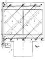
- control of the upper and lower wash pipes can also be advantageous, in which the upper and lower wash pipes are pivoted in opposite directions, so that the upper and lower wash jets always meet.
- This type of control offers an advantage especially when it is not necessary to wash flat, container-shaped items.
- the upper wash jets then act as a stabilizer for the wash ware, which is cleaned on its lower side by the lower wash jets.
- the possibly high pressure of the lower wash jets would possibly be able to lift pots, bowls, etc. out of their rinsing position without the stabilization mentioned.
- all the washing pipes are arranged parallel to one another. This simplifies the coordination of the respective pivoting movements.
- the brackets for the Items to be washed are arranged so that, in the case of flat items to be washed, the area to be washed lies transversely to the washing pipes. In this way, the surface to be rinsed is swept in a wiper-like movement by means of the pivoting movement of the individual washing pipes and thus cleaned over the entire surface.
- the wiper-like swiveling movement of the rinse jet repeatedly results in areas in which the mechanical action of the rinse jet is used to loosen the dirt, while in other areas the outflowing rinse water or the outflowing rinse liquor transports the loosened dirt downward.
- the nozzles are preferably arranged on the individual washing pipes in such a way that they are arranged exactly in the spaces between the individual flat items to be washed. As a result, each flat wash item is gripped and rinsed by a nozzle of each wash tube.
- these nozzles are further arranged inclined in the washing pipe with respect to the washing pipe axis so that they are at an acute angle, preferably at least 5 °, on the surface to be mainly cleaned, e.g. the inner bottom surface of a baking sheet or tray, any flat washware hits. Since flat wash items such as baking trays, trays or the like generally have a particularly dirty side, this is preferably cleaned by the inclined nozzles.
- the rinse jets meet here at the acute angle mentioned above, which improves the mechanical action mentioned.
- So-called flat jet nozzles are advantageously used.
- a large area of the items to be washed can be sprayed by means of such nozzles, the nozzle cross section being kept small.
- a small nozzle cross-section in turn ensures high pressure with which a "hard” jet is sprayed concentrated out of the washing pipe.
- a high pressure when the steel hits the wash ware, in turn has a high mechanical effect to loosen the dirt located there.
- the surface of the flat jet is advantageously aligned parallel to the wash tube axis. In this way, all areas that are hit by a washing nozzle are located in a plane that runs through the axis of rotation of the washing pipe. In this way, the angle setting of the washing pipes can be better determined for optimal use of space in the wash cabinet.
- the drive for a plurality of washing pipes is advantageously coupled to one another, a simple but reliable possibility of such a drive being a lever drive in which a rotary lever of each washing pipe is articulated in a push rod. Due to the back and forth movement of such a push rod, which can be effected, for example, by means of an eccentric drive, all of the washing pipes articulated on a push rod are pivoted back and forth synchronously.
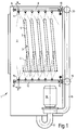
- the dishwasher 1 according to FIG. 1 comprises a washing compartment 2, in which flat items 3 such as baking trays, trays or the like are lined up one behind the other. Dashed lines show washware holders 4 which engage behind the edge 5 of the flat washware 3 and rest on the floor 6. On the lower edge 7, each wash ware is supported on the adjacent wash ware holder 4.
- the washing pipe 8 On its underside, the washing pipe 8 is equipped with a series of washing nozzles 11, which are designed as flat jet nozzles, as indicated by the dash-dotted angles at the outlet of the nozzles 11.
- a lower washing pipe 12 At the bottom of the washing compartment 2 there is a lower washing pipe 12, which, like the upper washing pipe 8, is rotatably supported at its ends 13, 14 and has washing nozzles 15, which, however, are arranged on the lower washing pipe 12 on its upper side.
- the nozzles 11 of the upper washing tube 8 are at an angle ⁇ in the direction of the items to be washed 3 inclined.
- the lower nozzles 15 are also inclined at an angle ⁇ in the direction of the items 3 to be washed.
- the angles ⁇ and ⁇ are dimensioned such that the rinsing jets of the washing nozzles 11, 15 strike the bottom 6 at an acute angle.
- a pump 16 is connected to the washing compartment 2 via a return 17.
- a pressure line 18 branches into two horizontal pressure pipes 19, 20, each of which is connected to a row of upper 8 and lower 12 washing pipes.
- a plurality of upper washing pipes 8 are articulated to a push rod 22 via a lever 21.
- the push rod 22 is in turn articulated on two pivot levers 23, 24, the pivot axes 25, 26 of which are located approximately at the level of the pivot tube axes 27.
- the pivot lever 24 is designed as an angled double lever, which in turn is articulated on a vertical push rod 27 at its upper end 28.
- a drive rod 30 is articulated, which is rotatably attached to an eccentric disc 31 at the output of a gear 32.
- the gear 32 is in a non-positive connection with a motor 33.
- the lower washing pipes 12 are also articulated via a lever 34 to a lower push rod 35, which in turn is articulated at its ends 36, 37 to two pivot levers 38, 39.
- the pivot lever 38 is also designed as an angled double lever which is articulated at its free end 40 to the vertical push rod 27 and to the drive rod 30.
- the two outer edge pipes 41, 42 are arranged rotated relative to the other upper washing pipes 8.
- edge washing jets 45, 46 which do not flow out of the edge washing nozzles 43, 44 run parallel to the remaining rinsing jets 47 of the inner washing pipes 8.
- the lower edge wash pipes 48, 49 are also rotated relative to the other lower wash pipes 12, so that the lower edge wash jets 50, 51 also do not run parallel to the other wash jets 52.
- All wash pipes 8, 12, 41, 42, 48, 49 move in the pivoting movement from a certain angle section above the items to be washed. Since the individual washing nozzles 11, 15, 43, 44 are designed as flat jet nozzles, they sweep over the items to be washed 3 over their entire height H. At every point in the items to be washed 3 there are processing intervals in which dirt is either mechanically loosened by the impinging jet or else the loosened dirt can run off with the wash water or the wash liquor.
- the space utilization is further improved by the twisted edge washing pipes 41, 42, 48, 49.
- These edge washing pipes avoid that they only spray the wall of the wash cabinet in their one extreme position. In their other extreme position, the twist enables them to spray the dishes 3 over a larger diagonal distance.
- the rotation of the edge wash tubes results in zones S, S 'where their rays 51, 50 intersect with the rays 52 of adjacent wash tubes 12.
- these cutting areas S, S ' are located in zones far away from the washing pipes 49, 12, where the mechanical action of individual jets diminishes due to the great distance. In the cutting areas S, S ', which represent the most distant distance for the respective washing pipes 12, 48, 49, there is an additional benefit from the mutual reinforcement.
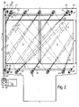
- 3 and 4 show special exemplary embodiments for a useful coordinated pivoting movement of the upper 8 and lower 12 washing pipes.
- This type of washing pipe control is particularly advantageous if not only flat washware 3, but possibly also pots or other container-shaped washware is to be washed.
- the upper washing tubes 8, with their washing jets 47 have a stabilizing effect on the container-shaped items to be washed (not shown), which is inserted into the dishwasher 1 with its opening facing down.
- the lower washing tubes 12 with their rinsing jets 52 can therefore be started at high pressure without the dishes being lifted.
- a washing pipe control system is shown, which could be called a parallel control system.
- the upper 8 and lower 15 wash pipes swivel in the same direction of rotation.
- the rinse jets 47, 52 of the upper 8 and lower 12 wash pipes always run parallel. They only interfere with one another in the short time when they pass each other. Most of the time and thus also in the area of the largest area that they run on the items 3 to be washed, they are undisturbed by one another.
- Each rinse jet 47, 52 is able to develop its full cleaning power undisturbed over the entire height H of the wash ware.
- the invention is not limited to the two illustrated exemplary embodiments of the washing pipe control.
- solutions are also conceivable in which the individual lower washing pipes 12 or the individual upper washing pipes 8 are at least partially decoupled from one another in their drive.
- the individual lower washing pipes 12 or the individual upper washing pipes 8 are at least partially decoupled from one another in their drive.
Landscapes
- Washing And Drying Of Tableware (AREA)
Applications Claiming Priority (2)
| Application Number | Priority Date | Filing Date | Title |
|---|---|---|---|
| DE19535090 | 1995-09-21 | ||
| DE19535090A DE19535090A1 (de) | 1995-09-21 | 1995-09-21 | Geschirrspülmaschine für gewerbliche Zwecke |
Publications (3)
| Publication Number | Publication Date |
|---|---|
| EP0764421A1 true EP0764421A1 (fr) | 1997-03-26 |
| EP0764421B1 EP0764421B1 (fr) | 2001-04-04 |
| EP0764421B9 EP0764421B9 (fr) | 2003-09-17 |
Family
ID=7772777
Family Applications (1)
| Application Number | Title | Priority Date | Filing Date |
|---|---|---|---|
| EP96112993A Expired - Lifetime EP0764421B9 (fr) | 1995-09-21 | 1996-08-13 | Machine à laver la vaisselle à usage industriel |
Country Status (3)
| Country | Link |
|---|---|
| EP (1) | EP0764421B9 (fr) |
| DE (2) | DE19535090A1 (fr) |
| ES (1) | ES2156607T3 (fr) |
Cited By (28)
| Publication number | Priority date | Publication date | Assignee | Title |
|---|---|---|---|---|
| US9295368B2 (en) | 2013-03-01 | 2016-03-29 | Whirlpool Corporation | Dishwasher with hydraulically driven sprayer |
| US9375128B2 (en) | 2011-09-22 | 2016-06-28 | Whirlpool Corporation | Dishwasher with spray system |
| US9532699B2 (en) | 2013-07-15 | 2017-01-03 | Whirlpool Corporation | Dishwasher with sprayer |
| US9532701B2 (en) | 2013-03-01 | 2017-01-03 | Whirlpool Corporation | Dishwasher with sprayer |
| US10058229B2 (en) | 2011-09-22 | 2018-08-28 | Whirlpool Corporation | Dishwasher with sprayer |
| US10213085B2 (en) | 2013-07-01 | 2019-02-26 | Whirlpool Corporation | Dishwasher for treating dishes |
| US10524634B2 (en) | 2017-09-29 | 2020-01-07 | Midea Group Co., Ltd. | Dishwasher with combined liquid and air sprayers |
| US10531781B2 (en) | 2017-09-29 | 2020-01-14 | Midea Group Co., Ltd. | Dishwasher with discretely directable tubular spray elements |
| US10631708B2 (en) | 2018-09-14 | 2020-04-28 | Midea Group Co., Ltd. | Dishwasher with docking arrangement for elevation-adjustable rack |
| US10765291B2 (en) | 2018-09-14 | 2020-09-08 | Midea Group Co., Ltd. | Dishwasher with check valve in rotatable docking port |
| US11000176B2 (en) | 2018-09-14 | 2021-05-11 | Midea Group Co., Ltd. | Dishwasher with rotatable diverter valve |
| US11026559B2 (en) | 2019-09-30 | 2021-06-08 | Midea Group Co., Ltd. | Dishwasher with image-based fluid condition sensing |
| US11045066B2 (en) | 2019-03-11 | 2021-06-29 | Midea Group Co., Ltd. | Dishwasher with keyed coupling to rack-mounted conduit |
| US11071440B2 (en) | 2018-09-14 | 2021-07-27 | Midea Group Co., Ltd. | Dishwasher with rack-mounted conduit return mechanism |
| US11185209B2 (en) | 2019-11-20 | 2021-11-30 | Midea Group Co., Ltd. | Dishwasher steam generator |
| US11191416B2 (en) | 2019-09-30 | 2021-12-07 | Midea Group Co., Ltd. | Dishwasher with image-based position sensor |
| US11202550B2 (en) | 2019-11-20 | 2021-12-21 | Midea Group Co., Ltd. | Dishwasher thermal imaging system |
| US11259681B2 (en) | 2019-09-30 | 2022-03-01 | Midea Group Co., Ltd | Dishwasher with image-based diagnostics |
| US11399690B2 (en) | 2019-09-30 | 2022-08-02 | Midea Group Co., Ltd. | Dishwasher with cam-based position sensor |
| US11412912B2 (en) | 2020-09-21 | 2022-08-16 | Midea Group Co., Ltd. | Dishwasher with tubular spray element slip ring alignment |
| US11464389B2 (en) | 2019-09-30 | 2022-10-11 | Midea Group Co., Ltd. | Dishwasher with image-based detergent sensing |
| US11484180B2 (en) | 2020-11-11 | 2022-11-01 | Midea Group Co., Ltd. | Dishwasher with tubular spray element including multiple selectable spray patterns |
| US11484183B2 (en) | 2019-09-30 | 2022-11-01 | Midea Group Co., Ltd. | Dishwasher with image-based object sensing |
| US11497374B2 (en) | 2020-02-19 | 2022-11-15 | Midea Group Co., Ltd. | Dishwasher with wall-mounted rotatable conduit |
| US11826001B2 (en) | 2022-02-15 | 2023-11-28 | Midea Group Co., Ltd. | Dishwasher with tubular spray element including elongated metal tube and retaining tab for mounting support member thereto |
| US12245735B2 (en) | 2022-02-25 | 2025-03-11 | Midea Group Co., Ltd. | Dishwasher including tubular spray element with intermediate support and/or fluid inlet |
| US12290225B2 (en) | 2017-09-29 | 2025-05-06 | Midea Group Co., Ltd. | Dishwasher with walking tubular spray element |
| US12329341B2 (en) | 2023-06-28 | 2025-06-17 | Midea Group Co., Ltd. | Dishwasher with rack-mounted tubular spray element assembly |
Families Citing this family (4)
| Publication number | Priority date | Publication date | Assignee | Title |
|---|---|---|---|---|
| DE102005015156A1 (de) | 2005-04-02 | 2006-10-05 | Premark Feg L.L.C., Wilmington | Transportgeschirrspülmaschine und Sprührohr dafür |
| US9492055B2 (en) | 2011-09-22 | 2016-11-15 | Whirlpool Corporation | Dishwasher with spray system |
| US9414736B2 (en) | 2011-09-22 | 2016-08-16 | Whirlpool Corporation | Dishwasher with directional spray |
| CN109620089B (zh) * | 2017-10-09 | 2021-12-07 | 青岛海尔洗碗机有限公司 | 一种洗碗机的喷淋器及洗碗机 |
Citations (6)
| Publication number | Priority date | Publication date | Assignee | Title |
|---|---|---|---|---|
| US2392540A (en) * | 1943-11-30 | 1946-01-08 | Homer F Lyman | Fluid spraying device for dishwashing apparatus |
| CH447499A (de) * | 1967-04-12 | 1967-11-30 | Ed Hildebrand Fa Ing | Geschirrwaschmaschine |
| DE1940574A1 (de) * | 1969-08-08 | 1971-02-11 | Exceltronic Ind Ltd | Geschirrspuelmaschine |
| DE1703099A1 (de) * | 1967-04-17 | 1972-01-13 | Jakob Kobelt | Geschirrwaschmaschine |
| GB2003840A (en) * | 1977-09-10 | 1979-03-21 | Woma Maasberg Co Gmbh W | A device for cleaning two- and three- dimensional objects such as plastics containers |
| JPH0433632A (ja) * | 1990-05-30 | 1992-02-05 | Mitsubishi Electric Corp | 食器洗浄機 |
Family Cites Families (3)
| Publication number | Priority date | Publication date | Assignee | Title |
|---|---|---|---|---|
| US3324867A (en) * | 1965-04-19 | 1967-06-13 | Charles E Freese | Dish washing machine |
| DE2442619C3 (de) * | 1974-09-05 | 1981-11-05 | Karl Winterhalter Kg, 7996 Meckenbeuren | Geschirspülmaschine, insbesondere zum Reinigen gewerblichen Geschirrs |
| US5415350A (en) * | 1993-03-06 | 1995-05-16 | Goldstar Co., Ltd. | Water spraying device for tableware washer |
-
1995
- 1995-09-21 DE DE19535090A patent/DE19535090A1/de not_active Withdrawn
-
1996
- 1996-08-13 DE DE59606694T patent/DE59606694D1/de not_active Expired - Lifetime
- 1996-08-13 EP EP96112993A patent/EP0764421B9/fr not_active Expired - Lifetime
- 1996-08-13 ES ES96112993T patent/ES2156607T3/es not_active Expired - Lifetime
Patent Citations (6)
| Publication number | Priority date | Publication date | Assignee | Title |
|---|---|---|---|---|
| US2392540A (en) * | 1943-11-30 | 1946-01-08 | Homer F Lyman | Fluid spraying device for dishwashing apparatus |
| CH447499A (de) * | 1967-04-12 | 1967-11-30 | Ed Hildebrand Fa Ing | Geschirrwaschmaschine |
| DE1703099A1 (de) * | 1967-04-17 | 1972-01-13 | Jakob Kobelt | Geschirrwaschmaschine |
| DE1940574A1 (de) * | 1969-08-08 | 1971-02-11 | Exceltronic Ind Ltd | Geschirrspuelmaschine |
| GB2003840A (en) * | 1977-09-10 | 1979-03-21 | Woma Maasberg Co Gmbh W | A device for cleaning two- and three- dimensional objects such as plastics containers |
| JPH0433632A (ja) * | 1990-05-30 | 1992-02-05 | Mitsubishi Electric Corp | 食器洗浄機 |
Non-Patent Citations (1)
| Title |
|---|
| PATENT ABSTRACTS OF JAPAN vol. 16, no. 202 14 May 1992 (1992-05-14) * |
Cited By (42)
| Publication number | Priority date | Publication date | Assignee | Title |
|---|---|---|---|---|
| US10602907B2 (en) | 2011-09-22 | 2020-03-31 | Whirlpool Corporation | Dishwasher with sprayer |
| US9375128B2 (en) | 2011-09-22 | 2016-06-28 | Whirlpool Corporation | Dishwasher with spray system |
| US10058229B2 (en) | 2011-09-22 | 2018-08-28 | Whirlpool Corporation | Dishwasher with sprayer |
| US9532701B2 (en) | 2013-03-01 | 2017-01-03 | Whirlpool Corporation | Dishwasher with sprayer |
| US10398283B2 (en) | 2013-03-01 | 2019-09-03 | Whirlpool Corporation | Dishwasher with sprayer |
| US9295368B2 (en) | 2013-03-01 | 2016-03-29 | Whirlpool Corporation | Dishwasher with hydraulically driven sprayer |
| US10213085B2 (en) | 2013-07-01 | 2019-02-26 | Whirlpool Corporation | Dishwasher for treating dishes |
| US9532699B2 (en) | 2013-07-15 | 2017-01-03 | Whirlpool Corporation | Dishwasher with sprayer |
| US9839340B2 (en) | 2013-07-15 | 2017-12-12 | Whirlpool Corporation | Dishwasher with sprayer |
| US10052010B2 (en) | 2013-07-15 | 2018-08-21 | Whirlpool Corporation | Dishwasher with sprayer |
| US11800963B2 (en) | 2017-09-29 | 2023-10-31 | Midea Group Co., Ltd. | Dishwasher with discretely directable tubular spray elements |
| US10531781B2 (en) | 2017-09-29 | 2020-01-14 | Midea Group Co., Ltd. | Dishwasher with discretely directable tubular spray elements |
| US12290225B2 (en) | 2017-09-29 | 2025-05-06 | Midea Group Co., Ltd. | Dishwasher with walking tubular spray element |
| US11058279B2 (en) | 2017-09-29 | 2021-07-13 | Midea Group Co., Ltd. | Dishwasher with discretely directable tubular spray elements |
| US10524634B2 (en) | 2017-09-29 | 2020-01-07 | Midea Group Co., Ltd. | Dishwasher with combined liquid and air sprayers |
| US10631708B2 (en) | 2018-09-14 | 2020-04-28 | Midea Group Co., Ltd. | Dishwasher with docking arrangement for elevation-adjustable rack |
| US10765291B2 (en) | 2018-09-14 | 2020-09-08 | Midea Group Co., Ltd. | Dishwasher with check valve in rotatable docking port |
| US11000176B2 (en) | 2018-09-14 | 2021-05-11 | Midea Group Co., Ltd. | Dishwasher with rotatable diverter valve |
| US11071440B2 (en) | 2018-09-14 | 2021-07-27 | Midea Group Co., Ltd. | Dishwasher with rack-mounted conduit return mechanism |
| US12268347B2 (en) | 2018-09-14 | 2025-04-08 | Midea Group Co., Ltd. | Dishwasher with rotatable diverter valve |
| US11045066B2 (en) | 2019-03-11 | 2021-06-29 | Midea Group Co., Ltd. | Dishwasher with keyed coupling to rack-mounted conduit |
| US11464389B2 (en) | 2019-09-30 | 2022-10-11 | Midea Group Co., Ltd. | Dishwasher with image-based detergent sensing |
| US11877711B2 (en) | 2019-09-30 | 2024-01-23 | Midea Group Co., Ltd. | Dishwasher with image-based detergent sensing |
| US11399690B2 (en) | 2019-09-30 | 2022-08-02 | Midea Group Co., Ltd. | Dishwasher with cam-based position sensor |
| US11026559B2 (en) | 2019-09-30 | 2021-06-08 | Midea Group Co., Ltd. | Dishwasher with image-based fluid condition sensing |
| US12251066B2 (en) | 2019-09-30 | 2025-03-18 | Midea Group Co., Ltd. | Dishwasher with image-based diagnostics |
| US12042111B2 (en) | 2019-09-30 | 2024-07-23 | Midea Group Co., Ltd. | Dishwasher with cam-based position sensor |
| US11484183B2 (en) | 2019-09-30 | 2022-11-01 | Midea Group Co., Ltd. | Dishwasher with image-based object sensing |
| US11896182B2 (en) | 2019-09-30 | 2024-02-13 | Midea Group Co., Ltd. | Dishwasher with image-based object sensing |
| US11766160B2 (en) | 2019-09-30 | 2023-09-26 | Midea Group Co., Ltd. | Dishwasher with image-based position sensor |
| US11191416B2 (en) | 2019-09-30 | 2021-12-07 | Midea Group Co., Ltd. | Dishwasher with image-based position sensor |
| US11889966B2 (en) | 2019-09-30 | 2024-02-06 | Midea Group Co., Ltd. | Dishwasher with image-based object sensing |
| US11259681B2 (en) | 2019-09-30 | 2022-03-01 | Midea Group Co., Ltd | Dishwasher with image-based diagnostics |
| US11864705B2 (en) | 2019-11-20 | 2024-01-09 | Midea Group Co., Ltd. | Dishwasher thermal imaging system |
| US11202550B2 (en) | 2019-11-20 | 2021-12-21 | Midea Group Co., Ltd. | Dishwasher thermal imaging system |
| US11185209B2 (en) | 2019-11-20 | 2021-11-30 | Midea Group Co., Ltd. | Dishwasher steam generator |
| US11497374B2 (en) | 2020-02-19 | 2022-11-15 | Midea Group Co., Ltd. | Dishwasher with wall-mounted rotatable conduit |
| US11412912B2 (en) | 2020-09-21 | 2022-08-16 | Midea Group Co., Ltd. | Dishwasher with tubular spray element slip ring alignment |
| US11484180B2 (en) | 2020-11-11 | 2022-11-01 | Midea Group Co., Ltd. | Dishwasher with tubular spray element including multiple selectable spray patterns |
| US11826001B2 (en) | 2022-02-15 | 2023-11-28 | Midea Group Co., Ltd. | Dishwasher with tubular spray element including elongated metal tube and retaining tab for mounting support member thereto |
| US12245735B2 (en) | 2022-02-25 | 2025-03-11 | Midea Group Co., Ltd. | Dishwasher including tubular spray element with intermediate support and/or fluid inlet |
| US12329341B2 (en) | 2023-06-28 | 2025-06-17 | Midea Group Co., Ltd. | Dishwasher with rack-mounted tubular spray element assembly |
Also Published As
| Publication number | Publication date |
|---|---|
| ES2156607T3 (es) | 2001-07-01 |
| DE59606694D1 (de) | 2001-05-10 |
| EP0764421B1 (fr) | 2001-04-04 |
| EP0764421B9 (fr) | 2003-09-17 |
| DE19535090A1 (de) | 1997-03-27 |
Similar Documents
| Publication | Publication Date | Title |
|---|---|---|
| EP0764421B1 (fr) | Machine à laver la vaisselle à usage industriel | |
| EP0943282B1 (fr) | Lave-vaiselle | |
| EP1731081B1 (fr) | Lave-vaisselle | |
| EP0997100B1 (fr) | Panier de lave-vaisselle | |
| DE69618563T2 (de) | Geschirrspüler mit drehbarem Sprüharm mit selektiv gespeisten Sprühdüsen und Verfahren | |
| DE10134917B4 (de) | Geschirrspülmaschine mit veränderbarer Flüssigkeitsverteilung | |
| DE10163184B4 (de) | Geschirrspülmaschine | |
| EP2441370B1 (fr) | Lave-vaisselle doté d'au moins un dispositif de vaporisation | |
| EP1252856A2 (fr) | Procédé pour laver la vaisselle | |
| EP2635172B1 (fr) | Lave-vaisselle équipé d'au moins un bras de pulvérisation rotatif | |
| DE2304035C2 (de) | Verfahren zum Spülen von Geschirr in einer Geschirrspülmaschine | |
| DE3816408A1 (de) | Geschirrspuelmaschine mit einer umsteuervorrichtung | |
| EP2601877A2 (fr) | Lave-vaisselle avec inversion automatique du sens de rotation du bras pulvérisateur | |
| DE60018345T2 (de) | Einheit von rotierenden Düsen der Geschirrspülmaschine ausgestattet mit einer Einrichtung zur horizontalen Verschiebung | |
| WO2003051171A1 (fr) | Lave-vaisselle | |
| DE2428991B2 (de) | Verfahren zum Reinigen von Geschirr in einer Haushaltgeschirrspülmaschine | |
| WO2006069827A1 (fr) | Lave-vaisselle comprenant des ecrans deflecteurs | |
| EP1046370A1 (fr) | Machine à laver la vaisselle à bande | |
| EP1681976B1 (fr) | Dispositif pour commander des canaux de pulverisation dans des lave-vaisselle | |
| EP1673000B1 (fr) | Lave-vaisselle a canaux de pulverisation integres | |
| EP2181637A2 (fr) | Lave-vaisselle doté d'un effet de rinçage amélioré | |
| DE102012202246B4 (de) | Geschirrspülmaschine mit einer Sprüheinrichtung | |
| DE102010032006A1 (de) | Spülmaschine mit Schwenksprüharm | |
| DE102008025207A1 (de) | Geschirrspülmaschine | |
| CH718296A2 (de) | Vorrichtung zur Reinigung von Gegenständen. |
Legal Events
| Date | Code | Title | Description |
|---|---|---|---|
| PUAI | Public reference made under article 153(3) epc to a published international application that has entered the european phase |
Free format text: ORIGINAL CODE: 0009012 |
|
| AK | Designated contracting states |
Kind code of ref document: A1 Designated state(s): CH DE ES FR GB IT LI |
|
| 17P | Request for examination filed |
Effective date: 19970701 |
|
| 17Q | First examination report despatched |
Effective date: 19981216 |
|
| GRAG | Despatch of communication of intention to grant |
Free format text: ORIGINAL CODE: EPIDOS AGRA |
|
| GRAG | Despatch of communication of intention to grant |
Free format text: ORIGINAL CODE: EPIDOS AGRA |
|
| GRAG | Despatch of communication of intention to grant |
Free format text: ORIGINAL CODE: EPIDOS AGRA |
|
| GRAH | Despatch of communication of intention to grant a patent |
Free format text: ORIGINAL CODE: EPIDOS IGRA |
|
| GRAH | Despatch of communication of intention to grant a patent |
Free format text: ORIGINAL CODE: EPIDOS IGRA |
|
| GRAA | (expected) grant |
Free format text: ORIGINAL CODE: 0009210 |
|
| AK | Designated contracting states |
Kind code of ref document: B1 Designated state(s): CH DE ES FR GB IT LI |
|
| REG | Reference to a national code |
Ref country code: CH Ref legal event code: EP |
|
| GBT | Gb: translation of ep patent filed (gb section 77(6)(a)/1977) |
Effective date: 20010404 |
|
| REF | Corresponds to: |
Ref document number: 59606694 Country of ref document: DE Date of ref document: 20010510 |
|
| REG | Reference to a national code |
Ref country code: CH Ref legal event code: NV Representative=s name: KELLER & PARTNER PATENTANWAELTE AG |
|
| REG | Reference to a national code |
Ref country code: ES Ref legal event code: FG2A Ref document number: 2156607 Country of ref document: ES Kind code of ref document: T3 |
|
| ITF | It: translation for a ep patent filed | ||
| ET | Fr: translation filed | ||
| REG | Reference to a national code |
Ref country code: GB Ref legal event code: IF02 |
|
| PLBE | No opposition filed within time limit |
Free format text: ORIGINAL CODE: 0009261 |
|
| STAA | Information on the status of an ep patent application or granted ep patent |
Free format text: STATUS: NO OPPOSITION FILED WITHIN TIME LIMIT |
|
| 26N | No opposition filed | ||
| PGFP | Annual fee paid to national office [announced via postgrant information from national office to epo] |
Ref country code: FR Payment date: 20030808 Year of fee payment: 8 |
|
| PGFP | Annual fee paid to national office [announced via postgrant information from national office to epo] |
Ref country code: GB Payment date: 20030813 Year of fee payment: 8 |
|
| PGFP | Annual fee paid to national office [announced via postgrant information from national office to epo] |
Ref country code: CH Payment date: 20030818 Year of fee payment: 8 |
|
| GBCC | Gb: corrected translation (of claims) filed (gb section 80(3)/1977) | ||
| ET1 | Fr: translation filed ** revision of the translation of the patent or the claims | ||
| PG25 | Lapsed in a contracting state [announced via postgrant information from national office to epo] |
Ref country code: GB Free format text: LAPSE BECAUSE OF NON-PAYMENT OF DUE FEES Effective date: 20040813 |
|
| PG25 | Lapsed in a contracting state [announced via postgrant information from national office to epo] |
Ref country code: LI Free format text: LAPSE BECAUSE OF NON-PAYMENT OF DUE FEES Effective date: 20040831 Ref country code: CH Free format text: LAPSE BECAUSE OF NON-PAYMENT OF DUE FEES Effective date: 20040831 |
|
| GBPC | Gb: european patent ceased through non-payment of renewal fee |
Effective date: 20040813 |
|
| REG | Reference to a national code |
Ref country code: CH Ref legal event code: PL |
|
| PG25 | Lapsed in a contracting state [announced via postgrant information from national office to epo] |
Ref country code: FR Free format text: LAPSE BECAUSE OF NON-PAYMENT OF DUE FEES Effective date: 20050429 |
|
| REG | Reference to a national code |
Ref country code: FR Ref legal event code: ST |
|
| PGFP | Annual fee paid to national office [announced via postgrant information from national office to epo] |
Ref country code: ES Payment date: 20060921 Year of fee payment: 11 |
|
| REG | Reference to a national code |
Ref country code: ES Ref legal event code: FD2A Effective date: 20070814 |
|
| PG25 | Lapsed in a contracting state [announced via postgrant information from national office to epo] |
Ref country code: ES Free format text: LAPSE BECAUSE OF NON-PAYMENT OF DUE FEES Effective date: 20070814 |
|
| PGFP | Annual fee paid to national office [announced via postgrant information from national office to epo] |
Ref country code: DE Payment date: 20090831 Year of fee payment: 14 |
|
| PGFP | Annual fee paid to national office [announced via postgrant information from national office to epo] |
Ref country code: IT Payment date: 20090813 Year of fee payment: 14 |
|
| PG25 | Lapsed in a contracting state [announced via postgrant information from national office to epo] |
Ref country code: IT Free format text: LAPSE BECAUSE OF NON-PAYMENT OF DUE FEES Effective date: 20100813 |
|
| REG | Reference to a national code |
Ref country code: DE Ref legal event code: R119 Ref document number: 59606694 Country of ref document: DE Effective date: 20110301 |
|
| PG25 | Lapsed in a contracting state [announced via postgrant information from national office to epo] |
Ref country code: DE Free format text: LAPSE BECAUSE OF NON-PAYMENT OF DUE FEES Effective date: 20110301 |