EP0765002A2 - Câble coaxial rayonnant et système de radiocommunication l'utilisant - Google Patents
Câble coaxial rayonnant et système de radiocommunication l'utilisant Download PDFInfo
- Publication number
- EP0765002A2 EP0765002A2 EP96114401A EP96114401A EP0765002A2 EP 0765002 A2 EP0765002 A2 EP 0765002A2 EP 96114401 A EP96114401 A EP 96114401A EP 96114401 A EP96114401 A EP 96114401A EP 0765002 A2 EP0765002 A2 EP 0765002A2
- Authority
- EP
- European Patent Office
- Prior art keywords
- cable
- slots
- length
- field
- coaxial cable
- Prior art date
- Legal status (The legal status is an assumption and is not a legal conclusion. Google has not performed a legal analysis and makes no representation as to the accuracy of the status listed.)
- Granted
Links
- 238000004891 communication Methods 0.000 title claims description 27
- 230000005855 radiation Effects 0.000 claims abstract description 17
- 239000004020 conductor Substances 0.000 claims abstract description 16
- 238000010168 coupling process Methods 0.000 claims abstract description 12
- 238000005859 coupling reaction Methods 0.000 claims abstract description 12
- 230000008878 coupling Effects 0.000 claims abstract description 11
- 239000003989 dielectric material Substances 0.000 claims abstract 2
- 230000004044 response Effects 0.000 claims description 14
- 230000005540 biological transmission Effects 0.000 claims description 5
- 230000000644 propagated effect Effects 0.000 claims description 5
- 238000000034 method Methods 0.000 claims 11
- 239000006260 foam Substances 0.000 abstract description 4
- 230000001413 cellular effect Effects 0.000 abstract description 2
- 230000033590 base-excision repair Effects 0.000 description 15
- 230000003534 oscillatory effect Effects 0.000 description 7
- 238000005388 cross polarization Methods 0.000 description 6
- 230000010355 oscillation Effects 0.000 description 5
- 230000005684 electric field Effects 0.000 description 4
- 230000008859 change Effects 0.000 description 2
- 230000000694 effects Effects 0.000 description 2
- 230000006872 improvement Effects 0.000 description 2
- 238000004519 manufacturing process Methods 0.000 description 2
- 238000005259 measurement Methods 0.000 description 2
- 238000012986 modification Methods 0.000 description 2
- 230000004048 modification Effects 0.000 description 2
- 230000010287 polarization Effects 0.000 description 2
- 238000003491 array Methods 0.000 description 1
- 230000015556 catabolic process Effects 0.000 description 1
- 238000006731 degradation reaction Methods 0.000 description 1
- 230000000593 degrading effect Effects 0.000 description 1
- 230000003292 diminished effect Effects 0.000 description 1
- 238000006073 displacement reaction Methods 0.000 description 1
- 230000000737 periodic effect Effects 0.000 description 1
- 230000009467 reduction Effects 0.000 description 1
- 238000000926 separation method Methods 0.000 description 1
Images


Classifications
-
- H—ELECTRICITY
- H04—ELECTRIC COMMUNICATION TECHNIQUE
- H04B—TRANSMISSION
- H04B5/00—Near-field transmission systems, e.g. inductive or capacitive transmission systems
- H04B5/40—Near-field transmission systems, e.g. inductive or capacitive transmission systems characterised by components specially adapted for near-field transmission
- H04B5/48—Transceivers
-
- H—ELECTRICITY
- H01—ELECTRIC ELEMENTS
- H01Q—ANTENNAS, i.e. RADIO AERIALS
- H01Q13/00—Waveguide horns or mouths; Slot antennas; Leaky-waveguide antennas; Equivalent structures causing radiation along the transmission path of a guided wave
- H01Q13/20—Non-resonant leaky-waveguide or transmission-line antennas; Equivalent structures causing radiation along the transmission path of a guided wave
- H01Q13/203—Leaky coaxial lines
-
- H—ELECTRICITY
- H04—ELECTRIC COMMUNICATION TECHNIQUE
- H04B—TRANSMISSION
- H04B5/00—Near-field transmission systems, e.g. inductive or capacitive transmission systems
- H04B5/20—Near-field transmission systems, e.g. inductive or capacitive transmission systems characterised by the transmission technique; characterised by the transmission medium
- H04B5/28—Near-field transmission systems, e.g. inductive or capacitive transmission systems characterised by the transmission technique; characterised by the transmission medium using the near field of leaky cables, e.g. of leaky coaxial cables
Definitions
- the present invention relates generally to radiating transmission lines, particularly slotted coaxial cables, and to radio communication systems that use such radiating transmission lines.
- FIG. 1 Radiating coaxial cable has been used for many years in various types of radio communication systems.
- a typical layout is shown in FIG. 1 where a cable of length L produces a near field at the point P ( ⁇ , z ) where the field is received by a "pick-up" horn H (whose axis makes an angle ⁇ relative to the cable's axis) connected to a receiver R.
- the field strength produced by such a cable can fluctuate rapidly as a function of the near-field axial position (i.e., ⁇ constant, z variable) along the length of the cable.
- the strength of the field produced by such a cable can vary rapidly as a function of frequency.
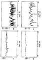
- FIG. 2a shows the measured field strength in dB versus axial distance along the cable at a given frequency for a coaxial radiating cable having many slots per wavelength. Superimposed upon these fluctuations is a gradual reduction in average field strength owing to the line's ohmic attenuation.
- the fluctuations along the cable are seen to be typically on the order of ⁇ 10 dB (but can approach -20 db).
- FIG. 2b shows the measured field strength in dB versus frequency at a given distance along the cable. Examination of FIG.
- One contemporary form of such a highly fluctuating radiating coaxial cable consists of a foam dielectric coaxial cable with a corrugated outer conductor which has radiating slots cut through the peaks of the corrugations.
- ⁇ phase velocity
- c speed of light
- the near-field patterns of this type of cable are highly oscillatory, as shown in FIGS. 2a and 2b, leading to excessive signal losses and high BERs.
- This type of cable produces both co-polar (i.e., transverse or perpendicular to the cable) and cross-polar (i.e., axial or parallel to the cable) components of electric field of about negligible difference (i.e., equal magnitude), as can be seen from the measured co-polar components of FIGS. 2a and 2b and the corresponding measured cross-polar patterns of FIGS. 2c and 2d.
- a second type of radiating coaxial cable has slots which are slanted with respect to the cable's axis (or a group of such slots to achieve wider bandwidth) spaced at periodic intervals ⁇ g along the length of the cable with the slant being the same from slot to slot.
- This same-slantedness and approximately ⁇ g slot spacing puts the transverse electric (co-polar) fields in the slots in phase, and thus all the slots radiate a transverse-polarized field off the cable at the same angle, , of nearly 90° from the cable's axis.
- the axial-electric (cross-polar) fields are also in phase and hence also radiate at an angle of 90° off the cable (though they are, typically, weaker, relative to their co-polar component, as compared to that for the first type of radiating cable (having many slots per ⁇ g ) since this second type has slots which are longer in the axial direction than in the transverse direction and are only slightly tilted relative to the axis).
- the co-polar pattern of this second type of radiating cable has smaller fluctuations than that of the first cable type.
- a third type of radiating coaxial cable with about ⁇ g /2 slot spacing and using reversed zig-zag-shaped slots has also been used.
- This arrangement also causes the transverse-electric (co-polar) fields to be in phase and radiate at nearly 90° from the cable's axis but causes the axial-electric (cross-polar) fields to be nearly out of phase (exactly so for exactly ⁇ g /2 slot spacing which, like exactly ⁇ g spacing in the second type of cable, is never used since a high input reflection occurs (i.e., the input VSWR to the cable "sees a spike")).
- This third type of radiating coaxial cable thus provides superior co-polar patterns as compared to those of the first and second types, but still radiates a substantial cross-polar component of electric field.
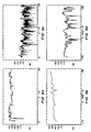
- the measured co-polar and cross-polar components from a typical zig-zag cable are shown in FIGS. 3a through 3d as there defined (note that by comparing FIGS. 3a with 3c or 3b with 3d that the cross-polar component is about -7 to -9 dB relative to the co-polar).
- TWLE two-wire line effect
- the outer metallic surface of the cable forms one line and an adjacent parallel surface (wall, floor, ceiling, etc.) forms the return line.
- the outgoing and return currents on this line produce a standing wave of current along the outside of the cable traveling at the speed of light (since the space between the cable and the wall is typically filled with air).
- This standing wave current also radiates and, when superimposed on that radiated from the slots, produces, typically, a highly oscillatory field. The strength of these oscillations is diminished (and can, in fact, in the absence of reflections, be made sufficiently small) by spacing the cable an adequate distance away from the wall.
- a cable having a cross-polar component cannot produce a sufficiently non-oscillatory field unless (in the absence of reflections) it is adequately spaced from the wall.
- the first type cannot produce such a result even in free space, i.e., even in the absence of a wall or other adjacent surface.
- This TWLE effect is seen from the measurements made on, for example, the third type (zig-zag) of cable, where the measured co-polar field of FIG. 3a (that measured when the cable is put against a dry-wall with slots pointing away from the wall) degrades to that of FIG.
- 3aa that measured when the cable is put against the same dry-wall covered with a 3 foot wide metallic strip with, again, the slots pointing away from the wall.
- first type of cable its patterns are so bad (many deep oscillations) even against a dry-wall (FIG. 2a or 2b) that the further degradation due to a metallic wall is inconsequential.
- the second type of cable will be better than the first but worse than the third when a metallic wall is present.
- a fourth type of radiating cable employs a number of slots forming a group or cell, where all the slots are tilted relative to the cable's axis, and where the groups or cells are repeated at specific intervals.
- the slots in each cell are arranged such that at any given frequency in the specified bandwidth only one constant phase-front is radiated.
- this type of cable can increase the bandwidth beyond that of the second and third types described above.
- the slots radiate both axial and transverse polarizations, and this cable also produces a TWLE due to its axial currents.
- the amplitude fluctuations of the near field, at a given observation point can vary widely with frequency across the operating bandwidth.
- the amplitude of the near-field fluctuations can, at a given frequency, also vary widely along the length of the cable. Both of these near-field fluctuations can lead to unacceptable signal loss or BERs.
- This poor performance is attributed to the high level of cross polarization produced by all of the above cable types (e.g., about 0 dB, higher than -7 dB, -7 dB, and higher than -7 dB, for the four cable types, respectively).
- this improvement requires that the co-polar radiation have small amplitude fluctuations and that the cross-polarization radiation be as low as possible.
- a further object of the invention is to provide such an improved radiating coaxial cable which, since it avoids any significant generation of cross-polarized fields, does not produce a TWLE or reflected cross-polar signals which reconvert to co-polar signals.
- a related object is to provide such a radiating coaxial cable which avoids any significant radiation attenuation of signals propagated longitudinally through the cable.
- Yet another object of this invention is to provide such an improved radiating coaxial cable which can be mounted close to, or even on, a wall (even a metallic wall) or other surface without significantly degrading the operation of the radio communication system in which the radiating cable is used.
- Still another object of the invention is to provide such an improved radiating coaxial cable which greatly reduces the problem of multipath-reflected cross-polar signals being reconverted to co-polar signals and hence allows either a small or large separation between the radiating cable and the receiver.
- a still further object of the invention is provide such an improved radiating coaxial cable that can be efficiently and economically manufactured in long lengths.
- Another object of this invention is to provide an improved radio communication system using such improved radiating coaxial cable.
- the foregoing objectives are realized by providing a radiating coaxial cable which includes one or more rows of slots to produce a radiated field polarized perpendicularly to the axis of the cable, and to substantially avoid the radiation of a field polarized parallel to the axis of the cable.
- the dimensions and location of the slots in the outer conductor of the cable are selected so as to produce, at any given point in the near field, a near-field pattern having only small amplitude fluctuations across the operating bandwidth.
- the radiating cable produces a near-field pattern having only small amplitude fluctuations along the effective length of the cable.
- the near-field amplitude fluctuations of the radiating cable are preferably less than about ⁇ 3 dB in either an indoor or outdoor environment over the operating bandwidth of the system and along the effective length of the cable (and at any perpendicular distance, ⁇ , from the cable ranging from about 1 foot to about 50 feet).
- the system of this invention yields extremely low BERs when used for digital communications, and low levels of distortion when used for analog communications, all at low loss.
- the system also has a wide bandwidth, so that data can be transmitted at high data rates.
- the improved radio communication system of this invention includes the above radiating cable located within or adjacent to a prescribed area containing a multiplicity of radio transmitters, receivers or transceivers ("radio units"), which may be either mobile or fixed. Signals are transmitted to and received from the various radio units via the radiating cable.
- radio units radio transmitters, receivers or transceivers
- FIGS. 4 and 5 illustrate a length L of a radiating coaxial cable 10 having a series of off-resonant slots 11 formed in one side of the cable (or, perhaps, on two diametrically opposite sides, etc., to ensure the best performance independent of wall-mounting position).
- a signal is fed into one end 12 of the cable 10 and propagated through the cable to a matched load 13 at the opposite end, a portion of the signal is radiated from the slots 11 along the entire length of the cable.
- the radiated field is polarized perpendicularly to the axis of the cable, and can be detected by radio units R.U. anywhere along the length of the cable.
- the cable can also receive radiated signals from the radio units R.U. anywhere along the length of the cable. These received signals are propagated through the cable to a receiver (not shown) at the end 12 of the cable.
- the radiating cable 10 may be used in a wide variety of different applications where multiple radio units, often mobile units, must communicate with one or more base stations within a defined area.
- a highway or railroad communication system in which the radiating cable extends along an open highway or railroad (or, also, in a tunnel) for constant communication with mobile radio units in the various vehicles on the open highway or railroad (or in the tunnel).
- a wireless local area network (WLAN) of personal computers, printers, servers and the like located in a common building or on a common floor. This invention is most useful in applications where the communication area is sufficiently large that the radiating cable 10 must be at least 60 feet in length.
- the dimensions, locations and configurations of the slots 11 in the cable 10 are selected to produce a substantially flat near-field pattern along the length of the cable, and across the operating bandwidth of the system.
- the near-field pattern of the radiating cable preferably varies by less than about ⁇ 3 dB over the operating bandwidth of the system and along the length of the cable.
- the bandwidth may be as high as that of the radiating cable (as defined below).
- each slot 11 is oriented with its elongated edges parallel to the axis of the cable, and the transverse dimension of the slot is made narrow.
- the slot width may be 0.200 inch. As the slot width is increased, the slot begins to radiate undesired cross-polarized fields of increasing strength.
- a coupling device such as a tab 14 of FIG. 5 (or, also, of FIG. 6a or FIG. 6b) is provided at each slot.
- the tabs 14 be formed as integral parts of the slot edges, in the central portion of one of the long edges of each slot.
- the tabs 14 may lie in the cylinder of the outer conductor of the cable, or the tabs may be bent into the interior of the cable for increased coupling.
- the phase of the slot's electric field is preferably reversed for successive slots 11 by forming the tabs 14 on alternating edges of successive slots, so that the tabs are on opposite edges of each pair of adjacent slots.
- both the slots 11 and the tabs 14 are chosen to avoid any significant radiation attenuation of the signals that are propagated longitudinally through the cable, thereby ensuring that the signal is radiated with adequate strength along the entire length of the cable.
- the radiated energy per unit length of the cable, as well as the signal radiation-attenuation per unit length of the cable, are relatively low.
- the slots 11 are all elongated in the axial direction, and the center-to-center spacing S is usually such that only a few slots are provided in each free space wavelength ⁇ .
- the slot length L is chosen to achieve the desired amount of radiation from each slot (by controlling the amount of transverse displacement current across the slot), which in turn controls the radiation attenuation of the signal along the length of the cable.
- the width W of the slot is chosen narrow enough to minimize the amount of cross-polarized radiation from the slot.
- the coaxial cable can be made with an outer conductor that is sufficiently rigid to hold the cable relatively straight, or an otherwise flexible or semi-flexible cable may be reinforced with one or more longitudinal elements that provide sufficient stiffness to hold the cable relatively straight.
- the radiating cable of this invention produces a substantially flat near-field pattern close to cable as well as at substantial distances from the cable.
- the cable can be mounted directly on a wall (preferably with its non-slotted side against the wall) or other surface so that it is not vulnerable to mechanical vibrations, air-vortex and physical damage.
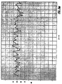
- FIG. 7a is a plot of the coupling loss (co-polar) measured along the length of a coaxial cable having an outer conductor with an outside diameter of 7/8 inch and a single row of slots extending along the length of the cable with a center-to-center spacing, S , of 2.75 inches.
- the slot edges forming the tabs alternated along the length of the cable, so that the tabs were on opposite edges of each pair of adjacent slots.
- Each tab was 0.910 inch long (in the axial direction) and 0.083 inch wide (in the circumferential direction).
- the measured cross-polar near field (FIG. 7c) was about 15 dB below the co-polar near field, and this low cross-polarization level is the reason for the excellent "flat" co-polar response.
- the radiating cable described above has a substantially flat near-field pattern, it provides reliable communications to and from radio units distributed along the length of the cable. This reliability is particularly useful in digital communications because it permits the attainment of low BERs. For example, digital data communications may require BERs as low as 10- 8 to avoid loss of significant data. These low BERs are attainable with a substantially flat near-field pattern because the fluctuations, or oscillations, in the pattern are of such a small amplitude that losses of one or more bits of data are virtually non-existent.
- the substantially flat near-field patterns of the present invention are also desirable for analog communication signals, to avoid spurious distortions in the analog signals.
- FIG. 7aa is the near-field co-polar pattern measured under the same conditions as FIG. 7a (both with the non-slotted side against the wall) but with a 3-foot metallic strip inserted on the dry-wall (the fact that FIG. 7aa is virtually identical to FIG. 7a indicates that no TWLE exists for this coaxial cable radiator).
- FIG. 7b illustrates the measured co-polar frequency response of the coaxial cable described above, across the operating bandwidth of the system.
- the frequency of the signal generator was swept across the frequency band of 1.700 to 1.850 GHz, which is the typical operating bandwidth of this coaxial cable for emanating angles of 92° ⁇ ⁇ 98°.
- the coaxial cable slot had the same dimensions and location described above. It can be seen that the measured signal amplitude was substantially flat ( ⁇ 2.5 dB) across the frequency band.
- the "pick-up" horn's axis was at an angle of 95° (a value between 92° and 98°) ( ⁇ 10°) to the coaxial cable's axis.
- FIG. 7d again shows the low level (-15 dB or less) of cross-polarization.
- FIGS. 9a through 9d are measurements like those of FIGS. 7a through 7d, but taken at a distance of 5 feet from the coaxial cable. It can be seen that the curves in FIGS. 9a and 9b are about as flat as than those in FIGS. 7a and 7b, and FIGS. 9c and 9d again show -15 dB cross polarization.
- the radiating coaxial cable described above has a substantially flat near-field pattern, it provides reliable communications to and from radio units distributed along the length of the coaxial cable. This reliability is particularly useful in digital communications because it permits the attainment of low BERs. For example, digital data communications may require BERs as low as 10 -8 to avoid loss of significant data. These low BERs are attainable with a substantially flat near-field pattern because the fluctuations, or oscillations, in the pattern are of such a small amplitude that losses of one or more bits of data are virtually non-existent.
- the substantially flat near-field patterns of the present invention are also desirable for analog communication signals, to avoid distortions in the analog signals.
- the radio units that receive radiated signals from the coaxial cable preferably include a directive antenna, such as the pyramidal horn mentioned above, having an aperture that is substantially perpendicular (e.g., within plus or minus 10 degrees) to the axis of the main radiation beam from the coaxial cable.
- This antenna preferably has a directive gain of at least about 10 dBi, and is positioned to receive radiation from at least about a 10-foot length of the coaxial cable.
- Other directive antennas are parabolic reflectors, corner reflectors, and slot or dipole arrays.
- optimum performance is that achieved with a highly directive "pick-up" horn (one with about 15 dBi; or more directive-gain and a good front-to-back ratio of about 18 dB or higher) to achieve responses like FIG. 7a (and 7b).
- a simple quarter-wave (dipole) antenna or two of them arranged in a space-diversity arrangement may suffice to give an adequately low BER ratio (where the BER is, of course, improved (reduced) using the above type optimum "pick-up" horn).
- FIG. 10c has significantly fewer severe dips in coupling.
Landscapes
- Engineering & Computer Science (AREA)
- Computer Networks & Wireless Communication (AREA)
- Signal Processing (AREA)
- Waveguide Aerials (AREA)
Applications Claiming Priority (2)
| Application Number | Priority Date | Filing Date | Title |
|---|---|---|---|
| US532141 | 1995-09-22 | ||
| US08/532,141 US5809429A (en) | 1995-09-22 | 1995-09-22 | Radiating coaxial cable and radio communication system using same |
Publications (3)
| Publication Number | Publication Date |
|---|---|
| EP0765002A2 true EP0765002A2 (fr) | 1997-03-26 |
| EP0765002A3 EP0765002A3 (fr) | 1997-10-22 |
| EP0765002B1 EP0765002B1 (fr) | 2003-04-23 |
Family
ID=24120529
Family Applications (1)
| Application Number | Title | Priority Date | Filing Date |
|---|---|---|---|
| EP96114401A Expired - Lifetime EP0765002B1 (fr) | 1995-09-22 | 1996-09-09 | Câble coaxial rayonnant et système de radiocommunication l'utilisant |
Country Status (3)
| Country | Link |
|---|---|
| US (1) | US5809429A (fr) |
| EP (1) | EP0765002B1 (fr) |
| DE (1) | DE69627599T2 (fr) |
Cited By (4)
| Publication number | Priority date | Publication date | Assignee | Title |
|---|---|---|---|---|
| EP1739789A1 (fr) | 2005-06-30 | 2007-01-03 | Institut Scientifique de Service Public | Câble coaxial rayonnant |
| WO2013139859A1 (fr) * | 2012-03-20 | 2013-09-26 | Siemens Aktiengesellschaft | Ligne de transmission à fuite et système de communication mimo fondé sur une ligne de transmission à fuite |
| DE102007048873B4 (de) * | 2007-05-25 | 2016-04-21 | Mitsubishi Electric Corp. | Koaxialzufuhr-Schlitzgruppenantenne und Fahrzeugradarvorrichtung |
| CN106848521A (zh) * | 2017-02-24 | 2017-06-13 | 通号(郑州)轨道交通科技有限公司 | 一种双极化漏泄波导 |
Families Citing this family (24)
| Publication number | Priority date | Publication date | Assignee | Title |
|---|---|---|---|---|
| DE19738381A1 (de) * | 1997-09-03 | 1999-03-04 | Alsthom Cge Alcatel | Abstrahlendes koaxiales Hochfrequenz-Kabel |
| US6195561B1 (en) * | 1998-07-03 | 2001-02-27 | Tunnel Radio Of America, Inc. | Antenna system for two-way UHF underground radio system |
| AU5589400A (en) | 1999-05-25 | 2000-12-12 | Transtek, Inc. | Facility-wide communication system and method |
| US6778845B2 (en) | 1999-07-13 | 2004-08-17 | Tx Rx Systems Inc. | Antenna/coupler assembly for coaxial cable |
| US6422900B1 (en) | 1999-09-15 | 2002-07-23 | Hh Tower Group | Coaxial cable coupling device |
| US6480163B1 (en) | 1999-12-16 | 2002-11-12 | Andrew Corporation | Radiating coaxial cable having helically diposed slots and radio communication system using same |
| US6413103B1 (en) | 2000-11-28 | 2002-07-02 | Apple Computer, Inc. | Method and apparatus for grounding microcoaxial cables inside a portable computing device |
| US7231224B1 (en) * | 2001-11-13 | 2007-06-12 | Atheros Communications, Inc. | Cable having embedded access points |
| US6610931B2 (en) * | 2001-12-05 | 2003-08-26 | Times Microwave Systems, Division Of Smiths Aerospace, Incorporated | Coaxial cable with tape outer conductor defining a plurality of indentations |
| US9374828B2 (en) * | 2003-01-13 | 2016-06-21 | Hamilton Sundstrand Corporation | Channel allocation for a multi-device communication system |
| US20070176840A1 (en) * | 2003-02-06 | 2007-08-02 | James Pristas | Multi-receiver communication system with distributed aperture antenna |
| US7091919B2 (en) * | 2003-12-30 | 2006-08-15 | Spx Corporation | Apparatus and method to increase apparent resonant slot length in a slotted coaxial antenna |
| US7616968B2 (en) * | 2004-03-23 | 2009-11-10 | Mine Radio Systems Inc. | System and method to facilitate overcoming a degradation in transmission through a radiating transmission line communication system |
| KR100766183B1 (ko) | 2006-02-22 | 2007-10-10 | 엘에스전선 주식회사 | 수직 편파용 누설동축케이블 |
| US8725188B1 (en) | 2007-07-20 | 2014-05-13 | Kutta Technologies, Inc. | Enclosed space communication systems and related methods |
| DE102008038246B4 (de) | 2008-08-18 | 2014-08-28 | Siemens Aktiengesellschaft | Verfahren, Computerprogrammprodukt, Gerät und Anordnung zum Bestimmen einer Position einer Kommunikations-Vorrichtung |
| US8197473B2 (en) * | 2009-02-20 | 2012-06-12 | Vivant Medical, Inc. | Leaky-wave antennas for medical applications |
| US8670708B2 (en) | 2010-09-29 | 2014-03-11 | E-Spectrum Technologies, Incorporated | Portable wireless through-the-earth communication system |
| US8867508B2 (en) * | 2011-01-05 | 2014-10-21 | Broadcom Corporation | Method and system for wireless access point radios integrated in a cable |
| US8705967B2 (en) * | 2011-07-28 | 2014-04-22 | Motorola Solutions, Inc. | Serially-distributed access points in a communication network |
| EP3182611A1 (fr) * | 2015-12-17 | 2017-06-21 | Swisscom AG | Système de communication mimo pour véhicules |
| US10478905B2 (en) * | 2016-09-15 | 2019-11-19 | Trilogy Communications, Inc. | Machine tool for forming radiating cable |
| US11469513B2 (en) * | 2019-06-26 | 2022-10-11 | Ohio State Innovation Foundation | Proximity sensor using a leaky coaxial cable |
| US12451615B2 (en) * | 2022-05-12 | 2025-10-21 | Dielectric, Llc | Broadband high-power pylon antenna |
Family Cites Families (27)
| Publication number | Priority date | Publication date | Assignee | Title |
|---|---|---|---|---|
| FR1094683A (fr) * | 1953-01-30 | 1955-05-23 | ||
| US3031666A (en) * | 1955-06-06 | 1962-04-24 | Sanders Associates Inc | Three conductor planar antenna |
| US2971193A (en) * | 1957-06-21 | 1961-02-07 | Rca Corp | Multiple slot antenna having radiating termination |
| US3648172A (en) * | 1968-10-02 | 1972-03-07 | Sumitomo Electric Industries | Circular leaky waveguide train communication system |
| US3691488A (en) * | 1970-09-14 | 1972-09-12 | Andrew Corp | Radiating coaxial cable and method of manufacture thereof |
| GB1324180A (en) * | 1970-12-30 | 1973-07-18 | Sumitomo Electric Industries | Vehicle communication systems |
| US3781725A (en) * | 1972-05-04 | 1973-12-25 | Sumitomo Electric Industries | Leaky coaxial cable |
| JPS49116587A (fr) * | 1973-03-13 | 1974-11-07 | ||
| GB1481485A (en) * | 1975-05-29 | 1977-07-27 | Furukawa Electric Co Ltd | Ultra-high-frequency leaky coaxial cable |
| JPS5256811A (en) * | 1975-11-05 | 1977-05-10 | Sumitomo Electric Ind Ltd | Moving subject communication system |
| DE2628755A1 (de) * | 1976-06-26 | 1978-01-05 | Licentia Gmbh | Richtantenne |
| GB1597125A (en) * | 1977-08-24 | 1981-09-03 | Bicc Ltd | Radiating cables |
| DE2812523A1 (de) * | 1978-03-22 | 1979-09-27 | Kabel Metallwerke Ghh | Abstrahlendes koaxiales hochfrequenz-kabel |
| DE3004882A1 (de) * | 1980-02-09 | 1981-08-20 | Kabel- und Metallwerke Gutehoffnungshütte AG, 3000 Hannover | Abstrahlendes koaxiales hochfrequenz-kabel |
| US4339733A (en) * | 1980-09-05 | 1982-07-13 | Times Fiber Communications, Inc. | Radiating cable |
| FR2520940B1 (fr) * | 1982-01-29 | 1985-09-27 | Lignes Telegraph Telephon | Procede de fabrication d'un cable coaxial rayonnant, cable obtenu par ce procede et ses utilisations |
| CA1195744A (fr) * | 1983-04-15 | 1985-10-22 | Hugh A. Edwards | Methode de fabrication de cables coaxiaux fuyants |
| FR2552272B1 (fr) * | 1983-09-15 | 1986-04-11 | Cables De Lyon Geoffroy Delore | Cable electrique coaxial rayonnant |
| JPS6089136A (ja) * | 1983-10-20 | 1985-05-20 | Furukawa Electric Co Ltd:The | 結合線路 |
| JPS62295525A (ja) * | 1986-06-16 | 1987-12-22 | Hitachi Cable Ltd | 漏洩同軸ケ−ブルの製造装置 |
| JPS63287104A (ja) * | 1987-05-19 | 1988-11-24 | Hitachi Cable Ltd | 漏洩同軸ケ−ブル |
| DE3723951A1 (de) * | 1987-07-20 | 1989-02-02 | Rheydt Kabelwerk Ag | Anordnung zur uebertragung von hochfrequenz-signalen |
| US4800351A (en) * | 1987-09-10 | 1989-01-24 | Andrew Corporation | Radiating coaxial cable with improved flame retardancy |
| JPH02288604A (ja) * | 1989-04-28 | 1990-11-28 | Hitachi Cable Ltd | 漏洩同軸ケーブル |
| NZ240907A (en) * | 1990-12-14 | 1995-01-27 | Ainsworth Tech Inc | Communication system: signal level adjusting interface between distribution and antenna systems |
| FR2685549B1 (fr) * | 1991-12-19 | 1994-01-28 | Alcatel Cable | Ligne haute frequence rayonnante. |
| US5414437A (en) * | 1993-06-28 | 1995-05-09 | Mahnad; Ali R. | Dual frequency interleaved slot antenna |
-
1995
- 1995-09-22 US US08/532,141 patent/US5809429A/en not_active Expired - Fee Related
-
1996
- 1996-09-09 EP EP96114401A patent/EP0765002B1/fr not_active Expired - Lifetime
- 1996-09-09 DE DE69627599T patent/DE69627599T2/de not_active Expired - Fee Related
Cited By (7)
| Publication number | Priority date | Publication date | Assignee | Title |
|---|---|---|---|---|
| EP1739789A1 (fr) | 2005-06-30 | 2007-01-03 | Institut Scientifique de Service Public | Câble coaxial rayonnant |
| US7498906B2 (en) | 2005-06-30 | 2009-03-03 | Institut Scientifique De Service Public | Radiating coaxial cable having spaced periodic aperture arrays |
| DE102007048873B4 (de) * | 2007-05-25 | 2016-04-21 | Mitsubishi Electric Corp. | Koaxialzufuhr-Schlitzgruppenantenne und Fahrzeugradarvorrichtung |
| US9379447B2 (en) | 2007-05-25 | 2016-06-28 | Mitsubishi Electric Corporation | Coaxially-fed slot array antenna and vehicle radar apparatus |
| WO2013139859A1 (fr) * | 2012-03-20 | 2013-09-26 | Siemens Aktiengesellschaft | Ligne de transmission à fuite et système de communication mimo fondé sur une ligne de transmission à fuite |
| CN106848521A (zh) * | 2017-02-24 | 2017-06-13 | 通号(郑州)轨道交通科技有限公司 | 一种双极化漏泄波导 |
| CN106848521B (zh) * | 2017-02-24 | 2022-05-10 | 通号电缆集团有限公司 | 一种双极化漏泄波导 |
Also Published As
| Publication number | Publication date |
|---|---|
| DE69627599D1 (de) | 2003-05-28 |
| EP0765002A3 (fr) | 1997-10-22 |
| DE69627599T2 (de) | 2003-11-13 |
| US5809429A (en) | 1998-09-15 |
| EP0765002B1 (fr) | 2003-04-23 |
Similar Documents
| Publication | Publication Date | Title |
|---|---|---|
| US5809429A (en) | Radiating coaxial cable and radio communication system using same | |
| US6480163B1 (en) | Radiating coaxial cable having helically diposed slots and radio communication system using same | |
| US6008773A (en) | Reflector-provided dipole antenna | |
| US7804460B2 (en) | Complex elements for antenna of radio frequency repeater and dipole array circular polarization antenna using the same | |
| EP0856909A1 (fr) | Antennes cellulaires | |
| US5717411A (en) | Radiating waveguide and radio communication system using same | |
| EP0973231A2 (fr) | Antenne directive à double polarisation avec des réflecteurs d'étranglement pour minimiser le rayonnement latéral | |
| US6252549B1 (en) | Apparatus for receiving and transmitting radio signals | |
| US9923281B2 (en) | Dual antenna system | |
| US7075494B2 (en) | Leaky-wave dual polarized slot type antenna | |
| US20030006938A1 (en) | Printed dipole antenna with dual spirals | |
| US7319429B2 (en) | Partially reflective surface antenna | |
| EP0825674A1 (fr) | Antenne en spirale monofilaire | |
| GB2548422B (en) | Antenna array assembly with conductive sidewalls for improved directivity | |
| EP0820116B1 (fr) | Antenne de radio mobile | |
| US5943023A (en) | Flared trough waveguide antenna | |
| US20030197646A1 (en) | Antenna with periodic electromagnetic mode suppression structures and method for same | |
| JPH07202562A (ja) | プリントダイポールアンテナ | |
| Ando | New DBS receiver antennas | |
| KR100854470B1 (ko) | 무선 중계기용 직교 다이폴 어레이 원편파 안테나 및 이를이용한 무선통신 중계 시스템 | |
| JPH0998019A (ja) | 偏波共用アンテナ | |
| JP4602585B2 (ja) | 漏れ波アンテナ | |
| JP3304019B2 (ja) | アレーアンテナ、それを備えた受信装置およびアレーアンテナにおける指向特性決定方法 | |
| Sironen et al. | A 60 GHz conical horn antenna excited with quasi-Yagi antenna | |
| JPH09214413A (ja) | 無線中継システム |
Legal Events
| Date | Code | Title | Description |
|---|---|---|---|
| PUAI | Public reference made under article 153(3) epc to a published international application that has entered the european phase |
Free format text: ORIGINAL CODE: 0009012 |
|
| AK | Designated contracting states |
Kind code of ref document: A2 Designated state(s): DE FR GB IT |
|
| PUAL | Search report despatched |
Free format text: ORIGINAL CODE: 0009013 |
|
| AK | Designated contracting states |
Kind code of ref document: A3 Designated state(s): DE FR GB IT |
|
| 17P | Request for examination filed |
Effective date: 19980421 |
|
| 17Q | First examination report despatched |
Effective date: 20010608 |
|
| GRAG | Despatch of communication of intention to grant |
Free format text: ORIGINAL CODE: EPIDOS AGRA |
|
| GRAG | Despatch of communication of intention to grant |
Free format text: ORIGINAL CODE: EPIDOS AGRA |
|
| GRAH | Despatch of communication of intention to grant a patent |
Free format text: ORIGINAL CODE: EPIDOS IGRA |
|
| GRAH | Despatch of communication of intention to grant a patent |
Free format text: ORIGINAL CODE: EPIDOS IGRA |
|
| GRAA | (expected) grant |
Free format text: ORIGINAL CODE: 0009210 |
|
| AK | Designated contracting states |
Designated state(s): DE FR GB IT |
|
| REG | Reference to a national code |
Ref country code: GB Ref legal event code: FG4D |
|
| REF | Corresponds to: |
Ref document number: 69627599 Country of ref document: DE Date of ref document: 20030528 Kind code of ref document: P |
|
| ET | Fr: translation filed | ||
| PLBE | No opposition filed within time limit |
Free format text: ORIGINAL CODE: 0009261 |
|
| STAA | Information on the status of an ep patent application or granted ep patent |
Free format text: STATUS: NO OPPOSITION FILED WITHIN TIME LIMIT |
|
| 26N | No opposition filed |
Effective date: 20040126 |
|
| PGFP | Annual fee paid to national office [announced via postgrant information from national office to epo] |
Ref country code: DE Payment date: 20040902 Year of fee payment: 9 |
|
| PGFP | Annual fee paid to national office [announced via postgrant information from national office to epo] |
Ref country code: GB Payment date: 20040908 Year of fee payment: 9 Ref country code: FR Payment date: 20040908 Year of fee payment: 9 |
|
| PG25 | Lapsed in a contracting state [announced via postgrant information from national office to epo] |
Ref country code: IT Free format text: LAPSE BECAUSE OF NON-PAYMENT OF DUE FEES Effective date: 20050909 Ref country code: GB Free format text: LAPSE BECAUSE OF NON-PAYMENT OF DUE FEES Effective date: 20050909 |
|
| PG25 | Lapsed in a contracting state [announced via postgrant information from national office to epo] |
Ref country code: DE Free format text: LAPSE BECAUSE OF NON-PAYMENT OF DUE FEES Effective date: 20060401 |
|
| GBPC | Gb: european patent ceased through non-payment of renewal fee |
Effective date: 20050909 |
|
| PG25 | Lapsed in a contracting state [announced via postgrant information from national office to epo] |
Ref country code: FR Free format text: LAPSE BECAUSE OF NON-PAYMENT OF DUE FEES Effective date: 20060531 |
|
| REG | Reference to a national code |
Ref country code: FR Ref legal event code: ST Effective date: 20060531 |